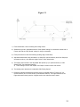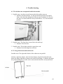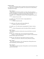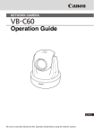
1
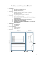
Declaration of Conformity According to the Medical Directive 93/42/EEC • • • • Type of equipment: Viewer for medical X-ray films. Brand name: Rollux Model: Rollux D Manufacturer: Breis & Co AB phone: +46 - (0)31 15 52 52 Banehagsliden 5 fax: +46 - (0)31 15 99 55 SE-414 51 Gothenburg Sweden Distributed by: Broadwest Corporation phone: 303-722-1500 304 Elati Street fax: 303-722-1507 Denver, CO 80223 USA The following harmonized European standards have been applied: Standards EN60 601-1-2 Test report issued by EMC Center Smâland EMC Center Smâland Regarding EMC emission EMC immunity Electrical safety The product is a Class 1 Medical product and it complies with the harmonized European safety standards. The product is CE marked in September 1999. As manufacturer, we declare under our sole responsibility that the equipment follows the provisions of the Directives stated above. January 12, 2001 Breis & Co AB Torgny Karlsson Managing Director 1 Technical data for X-ray viewer Rollux D • • • • • • Film capacity: 1200 films in the format 18x24 cm, 800 in the format 24x30 cm. Access time: Adjustable between 1,2 and 2,5 seconds for one step movements up or down. 90 to 140 seconds from frame 0 to frame 99. Illumination: Ten 54-watt fluorescent tubes. High frequency electronic ballasts provide flicker free light and low heat dissipation. Illumination adjustable between 4000 and 28000 lux. Luminance up to 10 000 candela/m2. Homogeneity: Illumination constant within +/- 10% across the whole light surface. Mains supply: 230V/50Hz 3A or 117V/60Hz 6A. Power consumption: 550W (maximum) 100W (stand by) Dimensions: 2 • • • • Documentation: Complete documentation and user’s manual in Swedish and English. Weight 320 kilo. Finish: Light Grey laminated. Manufacturer: Breis & Co AB Banehagsliden 5 S-414 51 Gothenburg Sweden • Tel. +46 - (0)31 15 52 52 Fax +46 - (0)31 15 99 55 Email [email protected] Distributor: Broadwest Corporation 191 University Blvd., #983 Denver, CO 80206-4613 USA Tel. 303 722-1500 Fax 303 722-1507 Email [email protected] 3 Contents 1. Technical description 1.1 Electrical installation 1.2 Fluorescent tubes 1.3 Mechanical installation 1.4 Dismounting of the film belt 1.4.2 Removing the belt to the rear 1.5 Mounting of a new belt 1.6 Connection of the keyboard and shutter control 1.6.1 Adjustment of the bar code reader 1.6.2 Installing a new bar code reader 1.7 Bar code reader 1.7.1 Adjusting the left and right shutter 1.7.2 Adjusting the upper and lower shutter 1.8 Emergency stop 1.9 Removal of the front panels 1.10 Light box assembly 1.11 Installation of tabletop 1.12 Digital or Analog mode 1.13 Installation of monitors and monitor support 2. Operation of the viewer 2.1 Power switch 2.2 Electrical power outlets 2.3 Keyboard connection 2.4 Keyboard functions 2.4.1 General 2.4.2 Belt movement 2.4.3 Light control 2.4.4 Shutter control 2.5 Foot switch 2.6 Service functions 2.6.1 Service function 1: Default film size 2.6.2 Service function 2: Manual belt movement 2.6.4 Service function 4: Enter correct frame number 2.6.5 Service function 5: Belt testing 2.6.6 Service function 6: Setting of default illumination. 2.6.8 Service function 8: Belt speed (movements > 2 frames). 2.6.9 Service function 9: Belt speed (movements ≤ 2 frames). 2.6.10 Service function 10: Number of operations. 2.6.11 Service function 11: Select foot switch function. 2.6.12 Service function 12: Setting of minimum illumination level. 2.6.13 Service function 13: Belt deceleration (downward). 2.6.14 Service function 14: Breaking motor speed (downwards). 2.6.15 Service function 15: Breaking motor speed (upwards). 2.6.16 Service function 16: Belt deceleration (upward). 4 2.6.17 2.6.19 2.6.20 2.6.21 2.6.22 2.6.23 Service function 17: Pulling motor speed. Service function 19: Belt tension (upwards). Service function 20: Belt tension (downwards). Service function 21: Belt size. Film loading mode (optional). Software release. 3. Maintenance and spare parts 3.1 Cleaning of the belt 3.2 General cleaning 3.3 Belt stop position 3.4 Changing of light tubes 3.5 Spare parts 3.5.1 Mechanical parts 3.5.2 Belt 3.5.3 Electrical and electronics 4. Trouble shooting 4.1 Belt does not run up/down 4.2 Lateral movement of the belt 4.3 Excessive static charging of the belt 4.4 Squeaking noises from the belt or idlers 4.5 Belt stops at different positions going up or down 4.6 Belt stops incorrectly 4.7 Belt stops too early 4.8 Error codes 4.8.1 Error 4 4.8.3 Error 6 4.8.4 Error 7 4.8.5 Error 8 5. Software flow charts 5.1 Motion control 5.2 Error detection 6. Block diagrams 6.1 6.2 CPU, keyboard connection, reset logic 6.3 Inputs (potentiometer and sensor board) 6.4 Power supply and motor control 6.5 Outputs and light control 6.6 Light box masking 7. Component lists and schematics 7.1.1 Communication board B280 7.1.2 5 7.2.1 CPU/Motor control layout (PC2014D) 7.2.2 CPU/Motor control schematics 1(4) 7.2.3 CPU/Motor control schematics 2(4) 7.2.4 CPU/Motor control schematics 3(4) 7.2.5 CPU/Motor control schematics 4(4) 7.2.6 CPU/Motor control component list 7.3.1 Keyboard (B13), layout 7.3.2 Keyboard schematics 1(2) 7.3.3 Keyboard schematics 2(2) 7.3.4 Keyboard component list 7.4.1 Light control board (B180), layout 7.4.2 Light control board schematics 7.4.3 Light control board component list 7.5 Electrical wiring 8. LEDs and connectors 8.1 CPU/Motor control 8.2 Mains filter 8.3 Light control board 9. Fuses 9.1 CPU/Motor control 9.2 Mains filter 9.3 Keyboard 9.4 Power inlet 10. Codes for programming of the bar code reader 11. User’s guide 6 7 1. TECHNICAL DESCRIPTION Picture. 1.1 Mains filter/light control board. 1.1.A Voltage setting jumper Jumper center-right: 117VAC Jumper center-left: 230VAC Picture. 1.2 Rear side door granting access to the light tubes. 1.2.A “Quarter turn” lock. 1.2.B Electronic ballasts. 1.1 Electrical installation Before connecting the viewer to either 220240VAC or 117VAC, please check the voltage setting on the mains filter board. To access this, open the right half of the rear sliding doors, remove the cover over the high voltage parts and locate the combined mains filter/light control board. Rewire the 230/117 V setting if necessary. Maximum current consumption is approx. 550W. 1.2 Fluorescent lamps For all models 10 each 54W T5 lamps are used. These types of lamp are 16 mm in diameter. All viewers are shipped with Philips 865 tubes, a color temperature of 6500K. (Call Broadwest for part # L54) Exchanging of lamp: Open the rear sliding doors, to get good access it might be convenient to remove the doors completely. To do that, lift them up as much as possible and pull the lower edge of the door out. You might need to bend the door slightly to get it out of the lower groove (Picture 1:4). The rear upper half of the light box can then be opened upwards to grant access to the fluorescent lamps. Release the left and right quarter turn locks and open the door. To obtain maximum lifetime, new tubes should be “burned in” at maximum brightness for 100 hours before using the dimming function. It is also recommended to do this after transporting the viewer, since the fluorescent powder might have become unevenly distributed during transport. Picture. 1.3 Adjustments of the wheels. Picture. 1.4 Springs holding the rear idler. Use an Allen key to lift off the spring. 1.4.A Lift off here. 1.4.B Grooves for the rear sliding doors. 1.3 Mechanical installation Unlock the wheel brakes and adjust the height of the cabinet using the M20 screw to which each wheel is bolted (Picture. 1:3). Use a 30 mm spanner. Adjust until the left and right side walls are parallel (fig. 1.1). Run the belt back and forth a couple of times and check for lateral movement. If the belt scratches against the bobbin side walls, the cabinet left and right walls are not parallel and the wheels have to be adjusted. If the belt touches the left side flanges of the bobbins, lower the left front wheel. In case of difficulties to get the belt alignment correct, it may help to disconnect the two springs holding the rear idler (Picture. 1:4). With the springs released there is less friction between the film belt and the conveyor belt; then the film belt should easily aligns correctly. If the belt still does not align correctly, the upper or lower bobbin can be moved slightly. Please note that either bobbin only can be moved a few millimeters to the right before they fall out of the bearing! See Picture. 1:5 Left Left SideSide Right Side Must be parallel Picture. 1.5 Nominal distance from inside the bobbin flange (the side towards the belt) to the sidewall should be 84 mm. 1.5.A Two set-screws that lock the bobbin shaft. fig 1.1 The left and right side wall of the cabinet can be adjusted to be parallel by adjusting the wheels. 1.4 Dismounting of the film belt The old belt can be removed from either the upper or the lower bobbin, but normally it’s more convenient to run the belt onto the upper bobbin and then remove it. The belt can be removed either to the front or to the back. Both ways are described here, but it is normally easier to remove/load belts to the rear. 9 • • • • 1.4.1 Removing the belt to the rear Run the belt to frame 99. Enter Service mode, select function 02 and run the belt all the way up to the upper bobbin. Remove the rear sliding doors as described under 1.2. Lead the belt out through the rear door opening and use service function 02 to run the old belt off the bobbin. 1.4.2 Removing the belt to the front The procedure is the same as above, but you have to remove all front covers. (See section 1.9) Picture. 1.8 Bar code reader adjustments 1.8.A Screws holding the reader 1.8.B LED indicating “good reads” 1.5 Mounting of a new belt New belts are shipped in a box with the belt bobbin mounted to a free rotating axle. This should make it possible to let the belt unwind directly from the box. • Place the box on a small table (or the table top if loading from front). • Make sure the bar codes are to the right (seen from front of viewer). This should be marked on the belt itself or on the box. • Connect the belt to the upper bobbin using the Velcro strips. • Run the belt on to the upper bobbin using the foot switch. o The machine will time-out for every 2nd frame since no bar code labels will be read, so you will have to press the switch repeatedly. o It is also possible to use service function 02, one person to press the key and one control the belt. Run the belt up and down and listen for noises. If it does not align properly, adjust as described under 1.3. 10 Picture. 1.9 Bar code reader connection 1.9.A FFC cable from bar code reader 1.9.B FFC connector 1.9.C Connector strips facing up at main board Pry open with a small screwdriver Locking tab Locking tab with cut out for cable. This cut out faces down on the reader, up on the main board. 1.6 Bar code reader The bar code reader is located inside the left half of the rear sliding doors, next to the main board. Its function is to read the frame numbers from the belt and also to initiate breaking and stopping of the motion at the given target frame. The stop position for the belt can be adjusted by moving the reader back and forth. If the reader should stop reading re-program it. Use the bar codes in appendix 1 and let the bar code reader read them one after another, starting with the upper code (“No flash”). 1.6.1 Adjustment of the bar code reader All shutter positions can be programmed, but the stopping position of the film clip must be more or less correct for the “Half frame” or “Digital mode” to operate properly. If the film clip does not stop at the light edge when in “Half frame” or in “Digital mode”, adjust the bar code reader back or forth. For additional adjustment you can bend the reader enclosure to open or close the angle indicated in picture 1.10. 1.6.2 Installing a new bar code reader THE CONNECTOR FOR THE FFC CABLE FROM THE READER TO THE MAIN BOARD MUST BE HANDLED VERY CAREFULLY. When opening the cable lock you can easily break the small plastic locking tab, or you can pull it totally out of the connector and lose it. If the locking tab should come off it can still be used, but it gets more difficult to lock the cable correctly. On main board: Connector strips on cable facing upwards, cable goes in above plastic tab. On reader: Connector strips facing down, cable goes in under plastic tab. Picture. 1.10 Bar code reader enclosure Open the locking tab by prying it straight out using a small screwdriver or similar tool. The tab should open approximately 1.5mm, be careful not to press it completely out of the connector. When installing, insert the cable as deep as possible . 11 figure. 1.2 Shutter opening is correct, but the belt is not stopping correctly in reference to the shutters. Move the bar code reader to correct. figure 1.3 Shutter opening is too large. Re-program the preset or adjust shutters. Picture 1.11 Potentiometer B (left shutter). 1.7 Adjustment of the shutter opening All presets for the shutters (18x24, 24x30, P1, etc) can be re-programmed by the user. If shutter positions should get wrong, the easiest way to correct it is to simply re-program the presets (see section 2.4). The following instructions might still be useful if you need to re-position the shutters after some major repair. If the shutter opening is too large or too small the position potentiometers have to be adjusted. At each potentiometer there is a sign showing which direction to turn to open or close the corresponding shutter. 1.7.1 Adjusting the left (B) and right (D) shutter Lift the timing belt from the cogwheel and turn the wheel. Shutter B (left): Turn clockwise to close the shutter. Shutter D (right): Turn counter-clockwise to close. See picture 1.12 1.7.2 Adjusting the upper (A) and lower (C) shutter Since the cogwheels are inside the light box, you have to turn the potentiometer shaft and make the timing belt slip. There is a hex nut (13 mm) on each potentiometer for this. It is easier to make the belt slip if you first run the shutter to the center of the viewing area. It might even be necessary to hold the belt while turning the potentiometer. Shutter A (upper): Turn clockwise to close the shutter. Shutter C (lower): Turn counter-clockwise to close. Picture 1.12 Potentiometer A (upper shutter) 1.12.A Hex nut (13 mm) for adjustment 12 1.8 Emergency stop There are two micro switches, one at each side, detecting the position of the upper conveyor belt idler. If any object should enter between the belt and the conveyor idler, the micro switches will cut the motor signal immediately and the motors will stop. Opening the front door also issues an emergency stop of the motors. The micro switch, located at the left side of the front door (picture 1.13.A), is connected in series with the left micro switch mentioned above. Due to features of the CPU the light will also dim to the minimum level when the emergency stop is activated. Picture 1.13 Micro switch for emergency stop (right side) 1.13.A Micro switch 1.13.B Upper conveyor belt idler 1.13.C Adjustment screws 1.11.D Bypass switch Picture 1.14 Upper left corner of motor board 1.14.A Jumper J1 for bypassing micro switches There are two ways to bypass this emergency stop: 1 To release an object stuck in the conveyor belt you hold down the red button (1.13.D) and run the belt upwards until the object is released. 2 If you need to bypass the micro switches permanently, you can close the jumper J1 on the motor control board (1.14.A) Picture 1.15 Reed relay on front door 1.15.A Reed relay 13 Picture 1.16 Upper front panel pushed up to give access to screws for front panels 1.16.A Upper panel 1.16.B Groove for the upper panel 1.9 Removal of the front panels The upper (curved) front panel slides in a groove on each sidewall of the cabinet. These can easily be removed by pushing up, see picture 1.16. As shown in pictures 1.16 and 1.17 the screws holding the upper film guide are now accessible. Loosen them no more than 2-3 turns, if you loosen too much the screw heads will pass through “key holes” in the film guide. After loosening the two screws on each side, the film guide can now be removed. After removing the film guide there are another two screws holding each side panel, one at the upper end and one at the lower. See picture 1.18 for the lower screw. Picture 1.18A Lower screw holding front panel Picture 1.17 Screws holding front panels 1.17.A Film guide 1.17.B Right side panel 1.17.C Right side wall 1.17.D Screws Picture 1.19 Screws holding left side panel visible 1.19.A Screw holding panel 1.19.B Screws for film guide (do not remove fully) 14 Picture 1.20 Installing the table 1.20.A Right side hinge positioned in the cutout 1.20.B Three Allen screws for each hinge 1.10 Light box assembly The complete light box and shutter assembly can be pushed out of the cabinet to make parts more accessible for service. • Run the belt to either the upper or lower bobbin. It is often more convenient to run it to the lower bobbin. • Remove the front panels as described in part 1.9 • Remove the rear sliding doors. • Release the two screws fixing the light box assembly to the side walls, see picture 1.17 • Disconnect cable harness X1 from underneath the circuit board shelf • Disconnect both the upper and lower bobbin motors. • Complete light box including shutter mechanism can now be pushed out. 1.11 Installation of table top If the unit has been shipped with the table removed, this has to be installed. • Fold down the left and right hinges for the table. • Place the cutouts at table back on the hinges. • Fit the screws using a 4 mm Allen key. 1.12 Digital or Analog mode This viewer is intended for the transition between analog films and digital images. For this purpose install a set of high quality monitors suitable for reading of mammography images, see next section. When monitors are installed, only the upper half of the viewing area is possible to use, so the viewer software must be configured for this. Follow this procedure: 1 Enter service mode (see 2.6). 2 Select function 32 (press 3 2) 3 Press “Service” twice to leave service mode. Now the lower shutter should close the lower half of the viewing area, and presets like 18x24 and 24x30 will automatically use only the upper half. To go back to analog mode select service function 32 again. Whenever selecting service function 32 viewer toggles between analog and digital mode. 15 1.13 Picture 1.21 Monitor support 1.21.A Two Allen screws 1.21.B Tabletop 1.21.C Monitor support 1.21.D Table rests on this screw Installation of monitors and monitor support To install the monitor support you need to remove the small supports for the table top from the left and right side walls. Lift up the table, these supports can then be removed. Use a 6 mm Allen key. Then install the monitor support using the same screws for the table support. The monitor support will now act also as table support. With the monitor support in place, you can install the monitors. There are 4 sets of elongated holes to make it possible to put the monitors close together and at a correct height. Pic 1.19 Vesa moun Picture 1.22 Vesa mount for monitors 16 2 Operation of the viewer 2.1 Power switch The power switch is located on the right side panel. The power switch cuts the power to the viewer except. You will still have power for the outlets on the front. To turn on the power you need to press STAND BY on the keyboard. Power consumption in stand by mode is very low; when the viewer is not to be used for a while, it is recommended to turn power off completely. 2.2 Power outlets There is a double power outlet fitted on the lower front, below the tabletop. Maximum output is 6A divided between the two outlets. These outlets will always have power regardless of the power switch. 2.3 Keypad The keypad is located on the right end of the front panel. Here you have keys for belt transport and shutter control. Illumination is controlled with a switch and a dimmer potentiometer located to the right of the keypad. 2.4 Keyboard 2.4.1 General functions STAND BY. Does not break the power to the circuit boards. When leaving in stand by mode the light is turned on at the pre-set level (service function 6). If the belt position does not correspond exactly to a frame position, the belt moves until the nearest frame is found. STOP. Stops the belt transport. 2.4.2 Moving the belt Enter a two-digit frame number between 01 (00 for a 100 frame belt) and the last frame number (can be 40, 60, 80 or 99). When the first digit has been entered, it can be erases with STOP. If a new number is entered during belt motion, the belt stops and starts to move to the new destination. The current frame number is indicated on the upper half of the display, the destination on the lower half. Moves the belt one frame up. Moves the belt one frame down. 17 2.4.3 Light control Light dimming is controlled with the potentiometer to the right of the keypad. Turn it clockwise to increase the illumination, counterclockwise to dim. When changing frames the illumination is automatically dimmed to minimum level not to cause unnecessary glare. The illumination is automatically turned on when leaving stand by mode, but it can be turned on or off using the circular push button below the light dimmer. This button is indicated with a green lighting ring. There is also a lights on/off switch built into the foot switch. 2.4.4 Shutter control 18x24 Masks the viewing area for 18x24 cm films. (Programmable Size) 24x30 Masks the viewing area for 24x30 cm films. F2 Masks the viewing area for 14” x 17” films. In this setting the film clip will stop at the top, in order to accommodate the 14” x 17” films. This function is disabled in digital mode. To leave F2 select 18x24 or 24x30. Each of these three presets is programmable, and can be changed. If masking does not fit your needs correctly, adjust shutters manually (see below) and press either of the 18x24, 24x30 or F1 keys and hold until the corresponding LED lights-up. The new shutter setting are now stored on that key. (Similar to programming your car radio) F1 Masks half of the viewing area and moves the belt in half frame steps. This can be used when there are no prior films to increase capacity to 200 examinations. This is especially useful in Digital mode, as you only have priors loaded in the viewer. 18 STORE SHUTTERS Stores the shutter settings made for each frame. Whenever coming back to a frame with stored settings, the shutters will be adjusted automatically. With this function a technician loading films can also preset the masking. When the radiologist then reads films every frame is masked automatically. There are two settings for this function, it can be either manual or automatically. 1. (LED off): After adjusting the shutters you press the key momentarily to store the setting. If no settings are stored the selected preset (18x24, 24x30, P1, etc) will be active for that frame. 2. (LED on): By holding down the key until the LED comes on, all settings are automatically stored. Return to manual mode by holding the key until the LED comes off. In automatic mode any shutter adjustments you have made will be stored when moving on to another frame. The set of keys shown to the left moves every shutter individually in or out. More then one shutter can be moved simultaneously. OPEN Opens all shutters for 18x24 or 24x30 cm films. Depends on if 18x24 or 24x30 is selected. 2.5 Foot switch The foot switch has three functions: 1. Press the right half of the switch to move the belt one frame down. 2. Press the left half of the switch to move the belt one frame up. 3. Press the center button to toggle the light on and off. Picture 1.20 Foot switch 1.20.A Right side moves belt up 1.20.B Left side moves belt down 1.20.C Light switch 19 2.6 Service functions To enter the service mode: Press SERVICE and check that the LED at the service key is lit. Enter the code: 9, 0, 5, 0 If the wrong code is entered, the service LED is turned off and you have to start over by pressing the SERVICE key. When the correct code is entered, a horizontal bar is lit in the upper left corner of the display. This bar is a command prompt indicating that you can enter commands. Use the SERVICE key to interrupt a service function. When at the command prompt you can leave the service mode by pressing SERVICE. 2.6.1 Service function 1. Default film size. Selects the default film format (18x24 or 24x30). Entering this function toggles between the two film formats. 18x24 is indicated by “24” on the display, 24x30 by “30”. The default setting for changing the film format changes the masking shutters. 2.6.2 Service function 2. Manual belt movement. Runs the belt upwards or downwards. Using this function the belt can be run all the way up or down to the end of the belt. Runs the belt upwards (towards higher frame numbers). Runs the belt downwards (towards higher lower numbers). It is also possible to run only one of the motors to release the belt tension. Run the upper motor downwards. Run the upper motor upwards. Run the lower motor downwards. Run the lower motor upwards. 20 2.6.4 Service function 4. Correcting the displayed frame number. Enter a new frame number if the display is incorrect. Choose function 4 and enter the correct frame number as a two digit number. 2.6.5 Service function 5. Test function. Runs the belt in a continuous loop from frame 5 to frame 30 and back. Turning off the power is the only way to interrupt this loop. 2.6.6 Service function 6. Setting the default illumination value. Adjust the illumination level with the + or - key. Choose service function 6 to store this setting as the default. The preset default is maximum level. 2.6.8 Service function 8. Belt speed. Sets the belt speed during motions longer then two frames. Increase the speed. Decrease the speed. Adjustable interval is 0 - 9, 9 is the maximum speed. Default is 5. Higher speed increases the risk for loss of films! 2.6.9 Service function 9. Belt speed. Sets the belt speed for one or two frame movements. Increase the speed. Decrease the speed. Adjustable interval is 0 - 9, 9 is the maximum speed. Default is 5. Higher speed increases the risk for loss of films! 1 0 2.6.10 Service function 10. Number of operations. Displays the number of operations made by the viewer. One operation is one movement of the belt, regardless off length. 21 1 1 1 2 1 3 1 1 4 5 1 6 1 7 2.6.11 Service function 11. Foot switch modes: Toggles between two different modes of operation for the foot switch. 1. Mode 00: The foot switch steps one frame up or down. The display shows 0. 2. Mode 01: The foot switch runs the belt while the switch is pressed. The display shows 1. 2.6.12 Service function 12. Minimum illumination. Adjust the minimum illumination level up or down with the + and - keys. While adjusting a number between 0 and 99 and proportional to the illumination is shown on the display. 2.6.13 Service function 13. Belt deceleration (downward). Use the + and - minus keys to adjust the deceleration of the belt after downward motion. A higher value is slower deceleration. Useable interval is 10 -31, default is 30. 2.6.14 Service function 14. Breaking motor speed (downward). Sets the minimum speed for the trailing motor during docking after downward motions. Low values are slower speed and more accurate docking. If the speed is too low, the belt might stop too early. Adjustable interval is 0 – 31, default is 15. 2.6.15 Service function 15. Breaking motor speed (upward). Sets the minimum speed for the trailing motor during docking after upward movements. Low values are slower speed and more accurate docking. If the speed is too low, the belt might stop too early. Adjustable interval is 0 – 31, default is 15. 2.6.16 Service function 16. Belt deceleration (upward). Use the + and - minus keys to adjust the deceleration of the belt after upward movements. A higher value is slower retardation. Useable interval is 10 -100, default is 50. 2.6.17 Service function 17. Pulling motor speed. Use the + and - minus keys to adjust the speed of the pulling motor during deceleration. A higher value is higher speed; Useable interval is 20 – 63, default is 45. 22 1 2 2 9 0 1 2 2 2 3 2 2 2 4 6 7 2.6.19 Service function 19. Belt tension (upward motion). Sets the belt tension during upward motions. Use + and - to adjust the tension. Useable interval is 3 – 12, default is 8. Higher value is higher tension. 2.6.20 Service function 20. Belt tension (downward motion). Sets the belt tension during downward motions. Use + and - to adjust the tension. Useable interval is 3 – 12, default is 8. Higher value is higher tension. 2.6.21 Service function 21. Belt length. Select what type of belt is used. Enter the number of frames as a two-digit number. Standard lengths are 40, 60, 80 or 100 frames. 2.6.22 Service function 22. Film loading mode. Activates and adjusts the film loading mode. Use the + and - keys to adjust the belt position for film loading. Every step equals approx. 4 centimeters. If the number of steps is set to 0, the function cannot be activated. 2.6.23 Service function 23. Software release. Use this to find the software release number. 2.6.24 Service function 24.Activates functions for removable magazines. This function is only relevant if you have a viewer with removable film magazines. Each time you select this function it toggles between on and off. With a 1 in the display the function is activated, with a 0 it is off. As default the function is de-activated. 2.6.26 Service function 26.Automatic light shut off. The time before automatic light shut off can be set. Use the + and - keys to adjust the time. The number displayed is minutes of in-activity before light shut off. If set to 0 there will be no automatic shut off. Default is 15. 2.6.27 Service function 27.Set light intensity default. This function is to set the default light intensity at Power on. Adjust the light intensity by using the + and - keys, then select this service function and the light intensity value will be stored and used after Power on. When leaving Stand by the latest set value will used, not the default. If no default value is set, the maximum intensity will be used. 23 Figure 2.1 1) Fixed acceleration, both for leading and trailing motors. 2) Speed during motion, adjustable with the "Slow Speed" setting for movements shorter then 3 frames and with the "High Speed" setting for longer movements. 3) Fixed point where to start final breaking (leading edge of belt label). 4) Adjustable deceleration with parameters: Up Slope (for upward motions) and Down Slope (for downward motions). User Beware: Higher value is lower deceleration. 5) The trailing motor breaks to the adjustable "Min Speed Up" (for upward motions) or "Min Speed Down" (for downward motions). a) Lower settings for both "Min Speed" and "Slope" results in fewer over-shoots. 6) The leading motor breaks to the adjustable "Min Pulling Speed". 7) Difference between the leading and trailing motor is adjusted with the "Tension Up" (for upward motions) and "Tension Down" (for downward motions). The higher difference, the higher belt tension during motion. A higher tension also reduces motion speed. 24 3 Maintenance 3.1 Cleaning of the film belt. The belt needs to be cleaned occasionally, how often depends on the environment (for example very dry conditions increases the static charging of the belt, which in turn attracts more dust), but once a year is normally enough. For normal cleaning we recommend an anti-static cleaner (Call Broadwest for part # ASC). The front side of the belt is easily accessible. For the rear side we recommend to remove the upper front panel and clean the belt as it winds up on the upper bobbin. 3.2 General cleaning Use any conventional detergent or alcohol if needed. 3.3 Adjusting the stop position for the belt. When the viewer has been used for some time the belt will start to run a few millimeters longer before it stops. To correct for this there are two service functions controlling breaking of the motors, one for running upwards, one for running downward. If the belt runs too far downwards, decrease the setting for service function 14. If the belt runs too far upwards, decrease the setting for service function 15. Should any of these service functions be set too low, the belt will stop before reaching its destination. Please beware of this! 3.4 Changing fluorescent tubes. Tubes used are high luminance 58W straight tubes (Call Broadwest for part # L58). Tubes should be changed approximately once a year. Procedure: 1. Run the belt to frame 0. 2. Enter service mode 02 and continue to run the belt all the way down so that it can be disconnected from the upper bobbin. 3. Open the shutters fully. 4. Move the opaque panel as much as possible to one side. (On some viewers there are screws holding the opaque panel at the top have to be removed.) 5. Bend the opaque panel out from inside the shutters. 6. Replace tubes. 7. When changing tubes, it is recommended to clean both sides of the opaque panel and inside the light box. When the opal pane is replaced, please check the position of the shutters; a timing belt may have slipped during the operation. 25 3.5 Spare parts When ordering spare parts, please state part number and description in accordance with this list. Also state the type and serial number of the viewer. This is found at the power inlet at the back of the viewer. 3.5.1 Mechanics Motor including gear (upper and lower are the same) Upper belt idler, Ø50 mm Lower belt idler, Ø100 mm Rear belt idler, Ø100 mm Upper conveyor idler, Ø50 mm Lower conveyor idler, Ø40 mm Flange bearing for idlers, axle Ø10 mm Conveyor belt Flange bearing for bobbins, axle Ø20 mm Motor cushion, PUR 10 mm Castors Spring, rear idler Spring, conveyor belt idler Cogwheel, potentiometer side shutters Cogwheel, potentiometer horizontal shutters RS-101 RS-102 RS-103 RS-104 RS-105 RS-106 RS-107 RS-108 RS-109 RS-110 RS-111 RS-112 RS-113 RS-114 RS-115 2 1 1 1 1 1 8 1 4 2 4 2 2 2 2 3.5.2 Film belt Complete belt, 40 frames Complete belt, 60 frames Complete belt, 80 frames Complete belt, 100 frames Film clips Rivets for film clips Film holding strings (including clips) RS-201M RS-202M RS-203M RS-204M RS-205 RS-206 RS-207 1 1 1 1 3.5.3 Electrical and electronics CPU/motor control board B195 Keyboard CPU Mains filter B102 Light control board B180 Light control/mains filter board B181 Keyboard, belt control Keyboard, shutter control Transformer TI-88085 Power switch Electronic ballast Philips HF-R 2x58 TLD Micro-switch (conveyor emergency stop) Power outlet (please also state country) Micro switch bypass RS-301 RS-321 RS-303 RS-304 RS-324 RS-322 RS-323 RS-307 RS-320 RS-309 RS-310 RS-312 RS-325 1 1 1 1 1 1 1 1 1 4 2 2 1 3/frame 26 4. Trouble shooting 4.1 The belt does not run upwards and/or downwards. 1. Possible cause: An object is stuck between the belt and the conveyor. a. Solution: Press the button 4.1.A and run the belt upwards at least half a frame. Also check the adjustment of the two micro switches (4.1.B) to be sure they are closed when the conveyor belt idler (4.1.C) is in the normal position. 2. Possible cause: The front door is open (below the table top). a. Solution: Close the door. 3. Possible cause: The belt has reached its upper/lower end. a. Solution: Is the belt length set correctly? 4.2 To large lateral movement of the belt. Possible cause: The right and left sides of the cabinet are not parallel. Solution: Adjust the wheels. Also check the distance from the left sidewall to the drum side flange. Should be 84 mms to the inside of the flange. To help the belt align the springs holding the rear idler can be removed while the belt is run up and down. 27 4.3 Excessive static charging of the belt. Possible cause: Unit is not grounded properly. Solution: Check for correct grounding of all antistatic brushes, bobbins and idlers. 4.4 Squeaking noise from the belt drum or idlers. 1. Possible cause: The flange bearings for the idlers are misaligned. a. Solution: Release the setscrews in the bearing and run the belt. If the noise does not disappear, try to move the idler one mm laterally (bend with a screw driver between the idler shaft and the bearing). Tighten the setscrews. 2. Possible cause: On the belt drum sidewalls there are triangular flanges bent into the drum core. a. Solution: Bend out the flanges so that they press firmly against the drum core. In each flange there is a hole in which an 8 mm Allen key can be inserted, bend out the flanges. Make sure you don’t bend the flange out of the core! Four of the flanges are screwed to the core and can’t be bent. 4.5 The belt stops at different positions going up or down. Possible cause: The drive parameters are incorrectly set. Solution: Adjust the drive parameters; see service functions 13 to 16. Example: If the belt stops too late going down, decrease the value in function 14 (and/or 13). 4.6 The belt stops incorrectly (the films does not correspond with the viewing area). 1. Possible cause: The bar code reader is in the wrong position. a. Solution: Move the bar code reader back or forth. 2. Possible cause: The shutters are not correctly adjusted. a. Solution: Adjust the shutters. Load two 24x30 films, one hanging and one standing. Open the shutters fully with the arrow keys. Make sure the belt stops more or less in the center of the viewing area (if not adjust the bar code reader). Press the “24x30” key. If the shutter opening is too small or too large, adjust the potentiometers for shutter A and/or C. Press “24x30” again to test. 4.7 The belt stops too early (either going up, going down or in both directions). Possible cause: The drive parameters are incorrectly set. Solution: a. If the problem is going up, increase the setting for service function 15 a few steps. b. If the problem is going down, increase the setting for service function 14 a few steps. Increasing the settings too much will result in a less tensed belt. 28 4.8 Error codes. To erase an error message you have to perform a belt movement operation. It can be a single step or a random access operation. You can enter service mode without erasing the error message. 4.8.1 Error 4 Distance between film frame positions is too long. If no frame position is detected within approx. 75 cm, this error code is issued. The belt then stops and tries to move backwards until the previous frame position is detected. 1. Possible cause: A damaged bar code label. Test by running the label past the reader. a. Solution: Fit a new label. 2. Possible cause: The bar code reader is wrongly adjusted (too high/low/angled). a. Solution: Adjust the reader. 3. Possible cause: The reader is off (is the red light on?). a. Solution: Turn power off and back on. 4. Possible cause: The reader must be reprogrammed (if it doesn’t read any labels). a. Solution: Reprogram the reader by reading all labels in appendix 1. 4.8.2 Error 6 The emergency stop micro switches at the conveyor belt idler are activated (picture 4.1). Possible cause: An object (like a pen) is stuck between the belt idlers. Solution: To release them press the switch 1:A (picture 4) and run the belt upwards until the object can be removed. Possible cause: The front door is open and the reed relay is activated. Solution: Close the door. Check the reed relay if this does not help. 4.8.3 Error 7 The belt has passed position 1 (0 for 100 frame belts). If the problem is not fixed automatically, run the belt upwards. 4.8.4 Error 8 The belt has passed the last position. If the problem is not fixed automatically, run the belt downwards. 29 7.2.1 Layout, motion board (B195) 30 7.2.2 CPU, SPI, RS232, light control, etc (B195) 31 7.2.3 Power supply and belt motor control (B195) 32 7.2.4 Shutter motor control (B195) 33 7.2.6 Motion board component lists (B195) 14 2,7 kΩ 7 6 4 2 3 4 1 3 1 1 2 R1 R8 R13 R15 R38 R50 R54 R68 R72 R79 R83 R86 R90 R384 R2 R3 R4 R5 R47 R51 R53 R58 R59 R71 R78 R80 R85 R87 R6 R7 R81 R88 R9 R10 R11 R12 R23 R24 R25 R26 R31 R34 R42 R43 R48 R49 R52 R60 R61 R63 R64 R65 R73 R82 R84 R89 R91 R14 R16 R17 R18 R44 R46 R74 R19 R21 R22 R37 R39 R62 R30 R29 R28 R27 R32 R33 R35 R36 R40 R41 R55 R56 R57 R45 R66 R67 R69 R70 R75 R77 R76 2 1 3 2 RN1 RN2 RN3 RN4 RN5 RN6 RN7 RN8 Resnet SIL 2k2*5 Resnet SIL 22k*5 Resnet SIL 10k*9(8) Resnet SIL 10k*5 24 D1 D2 D3 D4 D6 D7 D8 D9 D17 D18 D19 D20 BYW95C D21 D22 D23 D24 D25 D26 D27 D28 D29 D30 D31 D32 D10 D61 D5 1,5KE43 D11 D46 D43 D49 1N4007 D12 15V transient D41 D47 D48 5V8 transil 14 4 25 3 4 1 3 10 10 10 3 2 2 470 Ω 180 Ω 10 kΩ 1 kΩ 68 kΩ 1 Ω/2W 100 kΩ 22 kΩ 100 Ω 4,7 kΩ 24 Ω (27Ω) 10 MΩ 1Ω 0,1 Ω/3W LD1 LD2 LD3 LD4 LD5 LD6 LD7 LD8 LD23 LD22 LD9 LD10 LD15 LD17 LD19 LD21 LD25 LD26 LD27 LD29 LD11 LD12 LD13 LD14 LD16 LD18 LD20 LD24 LD28 LD30 3mm gul lysdiod IC1 IC19 IC26 IC2 IC3 IC4 IC12 7805 ULN2003 4094B Röd lysdiod 3mm Grön lysdiod 3 mm 34 2 2 2 1 3 1 1 1 1 1 4 IC5 IC15 IC6 IC7 IC8 IC10 IC9 IC11 IC13 IC14 IC16 IC17 DS26C32 IC18 IC20 IC21 IC22 IC23 IC24 IC25 TS952 L298N Bridge driver 74HC139 LM339 4051B DS26C31 5 7 1 4 2 2 T1 T3 T4 T10 T15 T2 T5 T7 T11 T12 T16 T17 T6 T8 D63 D64 D65 T9 T14 C3337, T13 BC557B BC547B TIP121 20ETS08 IRFZ48 IRF9Z34 12 C1 C2 C40 C41 C45 C46 C49 C50 C56 C57 C69 C70 C3 C10 C14 C48 C52 C59 C4 C5 C6 C8 C9 C11 C12 C13 C15 C16 C17 C18 C19 C20 C21 C22 C23 C24 C25 C26 C27 C28 C29 C30 C31 C32 C33 C34 C38 C39 C43 C44 C51 C54 C58 C61 C63 C64 C7 C35 C37 C36 C42 C47 C53 C60 C55 C62 C65 C66 C67 C68 330 nF 6 38 1 2 1 2 2 2 4 68HC908MR32 40109B 7815 40106B 10 µF35V 100 nF ceramic 1 µF 35V 22 pF 22 nF 100u/35V elektrolyt 5,6 pF 330 pF 10000µF 35V 35 1 1 1 2 4 2 1 1 7 4 1 1 XTAL J1 J2 RE1 RE2 F1 F2 F3 F4 K1 K5 K3 K4 K6-K9, K14-K16 K10-K14 K17 K18 4.9152MHz 2-pol stiftlist för bygel 2x7 pin stiftlist 3 pole/10A relay Fuse holder 2-pin rak Weidmuller 4-pin rak Weidmuller 16-pin Header 2-pin rak slits (AMP) 3-pin rak stiftlist (AMP) Skärmad RJ45 FCP ZIF-connector 36 7.3.1 Keyboard CPU (B402), layout 37 7.3.2 Keyboard CPU (B402) 38 7.4.1 Shutter keyboard layout 39 7.4.2 Shutter keyboard 40 7.5.1 Rollux keyboard layout 41 7.5.2 Rollux keyboard schematics 42 7.6.1 Light control board (B180), layout 43 7.6.2 Light control (B180), schematics 44 7.6.3 Light control (B180), component list Resistors 9 2 1 2 R1-9 R10,11 R14 RN1,2 100 Ω 2,7 kΩ 68 kΩ 1 kΩ ∗ 9 SIL Capacitors 1 C1 100 µF, 16V Semi conductors 9 T1-9 1 T10 BD139 BC547B Integrated circuits 1 IC1 1 IC2 2 IC3,4 1 IC5 ULN2803 PC815 PC847 PC817 Others 2 1 1 1 2-pole Weidmuller connector 10-pole Weidmuller connector 16-pole header Transformer, 2x9V 1,8VA K1,3 K2 K4 TR1 45 7.7.1 Light control and mains filter board (B181), PCB layout 46 7.7.2 Light control and mains filter board (B181), schematics 47 8 LED:s and connectors 48 9. Fuses 9.1 CPU/Motor control board F1 F2 F3 F4 24VAC input 30VDC for shutters Lower motor Upper motor 10 AT 1,6 AT 10 AT 10AT 9.2 Mains filter board F1 Mains 230VAC 5AT 9.3 Power inlet F1 Mains 230VAC 10AT 49 10. Codes for programming of the bar code reader If the bar code reader should stop reading, try to re-program it using these codes. Just make sure the power is on (red light in reader on) and pull this paper in front of the reader starting with the code “flashing mode - no flash” Rollux bar code configuration flashing mode - no flash (*) \47\43\47\51\00\60 communication parameters - baud rate - 19200 \41\08\60 communication parameters - data bits - 8 \43\60 communication parameters - parity - none \46\00\60 communication parameters - postamble - none \45\54\3E\00\60 disable all symbologies \41\4B\60 Code 128 / EAN 128 - active \41\5A\60 50 User Guide Toggles between ON and Stand by. Enter a two-digit number between 00 and 99 to access any film frame. By entering a new number during belt motion, the belt stops and moves to the new destination. The current frame number is displayed in the upper row of the display, the destination frame number in the lover row. Moves the belt upwards one frame. Moves the belt downwards one frame. Stops the belt motion. Can also be used to clear a frame number entry. (Push button with green light located to the right of the keypad.) Toggles the light on and off. There is also a button in the middle of the foot switch with the same function. Increases/decreases light intensity. Moves the belt one frame up or down. Press the right side to move up, the left side to move down. The middle button on the foot switch toggles light on and off. Tel: 800-232-2948 Fax: 800-625-1381 www.broadwest.com 51 User Guide Masks the viewing area for two rows of 18x24 cm films. Masks the viewing area for two rows of 24x30 cm films. Masks the viewing area for 35x43 cm films. The belt also stops with the film clip at the top of the viewing area to make it possible to load large films. To exit this mode press either 18x24 or 24x30. User programmable keys for shutter positions. Set the shutters to the desired position using the arrow keys and/or joystick. Press and hold any of the P1-P4 keys until the LED lights up to store the shutter position. The stored position can now be retrieved using the same P key. Light stays on until you press another command, e.g. 18x24 or P2. It takes two seconds to program. Sets the shutters to a small spot. The size of the spot can be programmed in the same way as the P1-P4 keys. Pressing the Spot key again, retrieves the previous shutter settings. Opens all shutters fully. The position for the upper and lower shutters depends on the 18x24/24x30 setting. Moves the upper, left, lower or right shutter inwards or outwards. The shutter moves while the key is pressed. Moves the belt one half of a frame when using the arrow keys. The upper half of the viewing area is masked. Stores shutter settings. Two different functions, toggle between them by keeping the key pressed until the LED goes on or off. (LED off): Save shutter settings you have made by pressing the key. (LED on): The shutter settings are stored automatically for each frame. Erase the shutter settings for all frames. First press Save Mask then OPEN (without releasing Save Mask). Moves the masking window in any direction. 52