1
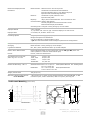
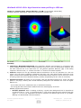
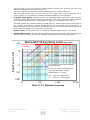
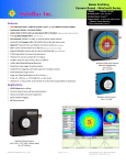
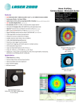
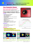
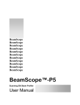
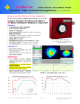
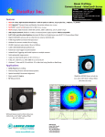
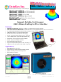
DataRay Inc.
Laser Beam Profilers
Advancing the Technology of Laser Analysis
WinCamD™-UCD12 1/2” CCD 14-bit ADC
WinCamD™-UCD23 2/3” CCD 14-bit ADC
WinCamD™-UHR 5.2 µm CMOS
WinCamD™-UHS High Speed–CMOS
BladeCamD™ 0.65” Ultra-Thin Probe Camera
WinCamD-FIR™ 8-14 µm
Compact, Portable, Port-Powered,
USB 2.0 Beam Profiling for PC or Intel-Mac
Features
◊
USB 2.0 port-powered; flexible 3 m cable; no external power supply required.
◊
0.65” mm Ultra-thin BladeCamD (includes ND filter) to fit tight beam trains
◊
14/10 Bit Digital CMOS/CCD cameras with on-chip 10-bit or external 14-bit ADC
◊
4 MB image buffer & on-board microprocessor
◊
Window-free sensors standard for no fringing
◊
20,000:1 electronic auto-shutter, 50 μs –1000 ms
◊
1,000:1 SNR options (30/60 dB Optical/Electrical)
◊
Pulsed laser auto-trigger and synchronization
◊
Parallel capture on multiple cameras
◊
Field-replaceable image sensors
◊
Large area TaperCamD options to 20 x 15 mm (p.7)
[0.50”/12 mm without filter]
◊ X-Ray, UV, 1310 nm (p.8) & 1475-1680 nm (p.10)
Applications
◊
CW & Pulsed laser profiling
◊
Field servicing of lasers and laser-based systems
◊
Optical assembly & instrument alignment
◊
Beam wander & logging
◊
M-Squared Measurements
Camera shown actual size
2.40 x 2.65 x 1.12” (x0.9” without filter) [61 x 67 x 28 mm]
WinCamD-U_Datasheet 0801a.doc
Rev. 0801a
Page 1 of 10
www.dataray.com
(203) 210-5065
DataRay Inc., Boulder Creek, CA
Powerful Beam Analysis Software
Beam Wander on a drifting Laser
Up to 8192 samples at a User Set interval.
Mean, RMS and Max. deviation.
Replay Fast or Slow.
Export to Excel, Paint, Bitmap or Clipboard.
With user overrides.
Auto-Inclusion Region on an Elliptical Beam
Automatically isolates the appropriate analysis region.
With user overrides.
Standard Linear Profile
with Gaussian Fit.
Logarithmic Profile
The same profile with
Averaging & Log 40 dB
display reveals structure
in the wings of the beam
at levels below 1%.
WinCamD-U_Datasheet 0801a.doc
Rev. 0801a
Page 2 of 10
www.dataray.com
(203) 210-5065
DataRay Inc., Boulder Creek, CA
DataRay Innovation - The company that brought you the first Windows-based CCD beam profiler, the first
Camera for confined spaces, the first software slider exposure and electronic auto-shutter, the first standard window-free
CCD for no fringing, the first auto-orientation on the ellipse & the first USB 2.0 beam profiling camera … has done it again.
Compact WinCamD- cameras- small enough to fit in your shirt pocket-or fit in a space 0.65” thick offer either the High
Speed capability required to capture single pulses to 20 kHz or High Resolution with a pixel size of 4.65 x 4.65 µm.
Features:
◊
◊
◊
◊
◊
Digital serial link for EMI immunity
XY profiles and centroids
Linear and logarithmic displays
Gaussian and Top Hat least squares fits
Ellipse Angle, Major, Minor, Mean Diameters
◊
◊
◊
◊
◊
Background capture and subtraction
Image & Intensity Zoom
Linear and area filters
Image Averaging, 1 to continuous
Compact design 0.65” Probe style for tight applications
WinCamD-U CCD & CMOS Sensor Specifications:
WinCamD™
-UCD12
-UCD23
-UHR
-UHS High Speed
BladeCamD™
Pixel Count &
1.4 M Pixel
1.4 M Pixel
1.3 MPixel,
355 kPixel,
1.3 MPixel,
H x V:
1360 x1024
1360 x1024
1280 x 1024
656 x 496
1280 x 1024
Sensor image area:
6.3 x 4.8 mm
8.8 x 6.6 mm
6.6 x 5.3 mm
6.5 x 4.9 μm
6.6 x 5.3 mm
Pixel dimension:
4.65 x 4.65 µm
6.45 x 6.45 µm
5.2 x 5.2 μm
9.9 x 9.9 μm
5.2 x 5.2 μm
Min. beam (10 pixels):
~47 µm
~65 µm
~52 μm
~100 μm
~52 μm
Shutter type:
Synchronous
Synchronous
Rolling
Synchronous
Rolling
Max. full frame rate:
~10 Hz
~10 Hz
~10 Hz
~10 Hz
~10 Hz
Max. ‘every pulse’ PRR:
~10 Hz
~10 Hz
~10 Hz
~10 Hz
~10 Hz
Single pulse capture PRR:
20 kHz
20 kHz
20 kHz
~205 kHz
20 kHz
Signal to RMS Noise (Opt./Elec.* dB):
1,000:1 (30/60* dB)
1,000:1 (30/60* dB)
1,000:1 (30/60* dB)
800:1 (29/58* dB)
1,000:1 (30/60* dB)
Electronic Shutter Dynamic Range:
43 dB
43 dB
43 dB
43 dB
43 dB
113** dB; 2.1011:1
113** dB; 2.1011:1
112** dB; 1.6.1011:1
113** dB; 2.1011:1
ND+Shutter+SNR Dynamic Range**:
113** dB; 2.1011:1
TaperCamD pixel size:
10.5 x 10.5 μm
10.5 x 10.5 μm
12 x 12 μm
22 x 22 μm
NA
TaperCamD20-15 pixel size:
14.5 x 14.5 μm
14.5 x 14.5 μm
16 x 16 μm
31 x 31 μm
NA
ADC:
14-bit (16384 levels)
14-bit (16384 levels)
10-bit (1024 levels)
10-bit (1024 levels)
10-bit (1024 levels)
* OK, we agree that quoting electrical dB for optical SNR is a nonsense, but some suppliers do this, so we offer a comparable specification.
** OK, we agree that Dynamic Range that includes removable ND filters is also nonsense, but some suppliers do this, so we offer comparable specification with ND 4.
Common WinCamD Series Specifications: [Specifications are subject to change without notice]
Wavelength: WinCamD
-1310
-NIR
-FIR
-UV
~350 to 1150 nm
~350 to 1330 nm. Residual silicon response. 1290 nm long Pass filter provided.
~1480 to 1680 nm. NIR to Visible phosphor, 40 μm FWHM (Erbium response)
~8 to 14 µm 23.5 µm pixel pitch, 320 x 240 pixels, 7.5 x 6.6 mm
~190 to 1150 nm UV converters with wavelength options down to X-ray. UV
resolution to 1 μm.
High dynamic range
20,000:1 (43 dB) continuously variable auto electronic shutter, <50 μs to 1.0 s.
Additional 10,000:1 ND filter + 5:1 electronic control to give 109:1.
Pulsed lasers
Auto-trigger sync, TTL input trigger, TTL output trigger – not available on -UHS
Compact- with ND filter
WinCamD-2.40” x 2.65” x 1.12” BladeCamD- 4.5 x 1.8 x 0.65”
Interface
Port Powered USB 2.0 for laptops & desktops. 3 m standard thin cable, 5 m option.
Multiple Heads:
1 – 16 cameras. Parallel capture, serial read.
ISO 11146
Beam profile Second moment processing
Certification
RoHS, WEEE, CE
Measurable Sources
Measured Beam Powers
RoHS
WEEE
CW beams, Pulsed sources. CW to >20 kHz with single pulse isolation (UHS)
User configurable Synchronous, Asynchronous & Variable Delay trigger options.
Software programmable trigger input, +ve or –ve edge, 50 Ω or 1 kΩ
See the Saturation Beam Power/Pulse Energy Graph and Notes, below.
Manual Beam Attenuation: Provided ND 4.0 (10,000:1) C-mount Neutral Density filters. [ND 4.0 at 546 nm,
higher in blue, lower in near IR.] Screw stackable ND 1, 2, 3, 4, 5 available.
Options: EAM-2: 4-wheel stepped variable attenuator, 0 to 90 dB
CUB and CUB-UV 3 to 10 % beam samplers for high power beams
1% and 0.05% Holographic Beam Samplers (by gentec-eo)
Measurement Accuracy
WinCamD-U_Datasheet 0801a.doc
Rev. 0801a
0.1 μm processing resolution for interpolated diameters. Absolute accuracy is beam
profile dependent – ~1 μm accuracy is frequently achievable.
Centroid accuracy is also beam dependent. It can be as good as ±1 μm since it is
arithmetically derived from all pixels above the centroid clip level.
Page 3 of 10
www.dataray.com
(203) 210-5065
DataRay Inc., Boulder Creek, CA
Measured & Displayed Profile
Parameters
Beam Diameter: Diameter at two user set Clip levels
Gaussian & Second Moment beam diameters
Equivalent diameter above a user defined Clip level
Equivalent Slit and Knife Edge diameters
Beam Fit:
Gaussian & Top Hat profile fit & % fit
Equivalent Slit profile
Ellipticity:
Major, Minor & Mean diameters. Auto-orientation of axes.
Centroid Position: Relative and absolute
Intensity Weighted Centroid and Geometric Center
Beam Wander Display and Statistics
Smoothing Filter: Triangular running average up to 10% FWHM
Displayed Profiles
2-D & 3-D plots
10, 16, 256 or max. colors or gray. Contoured display at 10 and 16 color.
X-Y Profiles, 2D, 3D Plots. Zoom to x10
Displayed Plots
Processing Options
Image & profile averaging, 1, 5, 10, 20, Continuous
Background Capture and Subtraction
User set rectangular or elliptical Capture region
*.job files save all WinCamD custom settings for particular test configurations
Pass/Fail display
Averaging
Log data and statistics
On-screen, in selectable Pass/Fail colors. Ideal for QA & Production.
Beam dimension running average up to 50 samples
Min., Max., Mean, Standard Deviation. Up to 4096 samples
Relative Power Measurement
Rolling histogram based on user’s initial input. Units of mW, µJ, dBm, % or user
choice (relative to a reference measurement input)
Fluence, within user defined area
Fluence
Chip depth from front of case
/filter ring all ±~0.5 mm
-UCD12
-UHR, -UHS
-UCD23
-BladeCamD
Outline and Mounting L x W x D
WinCamD-Series 2.65 x 2.4 x 0.9/1.13” Without/With ND4 filter See Drawing below
67 x 61 x 23/29 mm
BladeCamD
4.5 x 1.8 x 0.5/0.65”
Without/With ND4 filter
11.43 x 45.72 x 12.7 mm
Weight, Camera Head
155 gm (5.5 oz)
Minimum Computer Requirements:
PC or Intel-Mac
1 GHz Pentium IV or higher running Windows XP/Vista; 512/1024 MB RAM; 10 MB
Hard Drive space; 1024 x 768 monitor, USB 2.0 hi-power (500 mA) port.
Outline and Mounting
7.3/15.1
8.7/16.5
7.5/15.3
5.0/ 8.8
mm
mm
mm
mm
(not to scale)
Threaded #4-40
4 places
2.40
2.25
WinCamD Series
.65”
1.20
C-Mount
1.0"-32 UNC-2B
1/4"-20
0.3" deep
BladeCamD™
WinCamD-U_Datasheet 0801a.doc
Rev. 0801a
2.65 2.475
Page 4 of 10
1.525
0.175 0
0.90
1.13 0.70
0.15
0
0
www.dataray.com
(203) 210-5065
DataRay Inc., Boulder Creek, CA
Saturation Beam Power/ Pulse Energy Graphs
These two graphs allow you to simply determine the approximate maximum CW optical power (above) or pulse energy
(below) that the standard WinCamD-U configuration can measure for your beam diameter and wavelength without
additional attenuation. The Saturation Limit assumes:
- The provided ND 4.0 filter in place
- The electronic shutter set at 40 μs, its lowest value
- The ADC gain set at 1, its lowest value
- The beam onto the ND filter must not exceed 5 W total power or 100 mW/per mm2. [10 W/per cm2]
400 nm
500 nm
1064 nm
675 nm
800 nm
400 nm
500 nm
1064 nm
675 nm
800 nm
The lower limit in the standard configuration is ~10-5 x the Saturation Limit.
Use the graph right to estimate for other wavelengths.
Relative Exposure vs. Wavelength
100
10
1
300
500
700
900
1100
Wavelength in nm
WinCamD-U_Datasheet 0801a.doc
Rev. 0801a
Page 5 of 10
www.dataray.com
(203) 210-5065
DataRay Inc., Boulder Creek, CA
ORDERING INFORMATION
◊
3 Year Warranty
◊
Free Software Upgrades
◊
30 Day Sale or Return Evaluation PO
A Complete System comprises: Camera, ND 4.0 filter, Software, 3 m (10 ft) Cable, User Manual.
Generate the Part Number based upon the component descriptions, and limitations, in the table.
Your CCD or CMOS chip choice does not affect the system price except for the
Part Number
=
Camera type
+
CCD/ CMOS chip
2/3”
+
CCD chip which is higher.
Suffix (if required)
WinCamD
-UCD12/UHS, UHR
TaperCamD
-UCD12
-UV
-1310
TaperCamD20-15
-UCD23
-NIR
e.g. WinCamD-UHR is a complete working system with a High Resolution CMOS with 5.2 μm pixels.
TaperCamD-1310 is a complete working system with a 14.4 x 10.8 mm FO Taper for 1310 nm.
Part Number component descriptions
WinCamD
Complete working USB 2.0 camera system. Add CMOS chip extension to generate Part #.
TaperCamD
WinCamD-UCD12 with 14.4 x 10.8 mm 1.6:1 FO taper on the sensor
TaperCamD20-15
WinCamD-UCD23 with 20 x 15 mm 2.27:1 FO taper on the sensor – only with –UCD23 chip.
-UCD12
½” CCD sensor for CW and pulsed,
1360 x 1024 pixels
4.65 x 4.65 µm
-UCD23
2/3”
1360 x1024 pixels
6.45 x 6.45 µm
CCD sensor for CW and pulsed,
-UHR
½” CMOS sensor for CW and low PRR, 1280 x 1024 pixels
5.2 x 5.2 μm
-UHS
½” CMOS sensor for CW and pulsed,
9.9 x 9.9 μm
-1310
Adds 50 mm C-mount tube and long-pass filter for 1290 to 1350 nm work.
656 x 496 pixels
-UV
Camera with 3 mm UG11 filter instead of ND 4.0. Works at 260 through 380 nm.
-NIR
On-chip IR to visible phosphor converter for 1480 to 1600 nm.
-
Extra Cameras, priced lower than systems, programmed to only work as additional cameras on the same PC.
Extra cameras, come with Cable, Mount and ND filter, but no Software or User Manual. Confirm with factory.
Add additional suffix -X to the system Part #. E.g.: WinCamD-UHS becomes WinCamD-UHS-X
Accessories
EAM-2
Variable Attenuator, 93 dB optical dynamic range. Max.: 1 W/cm2 /100 mJ/cm2.
CUB & CUB-UV
Vis & UV Beamsplitters, 3% to 10% (polarization dependent) C-mount to camera.
ND1.0, ND2.0,
ND3.0, ND4.0,
ND5.0
Additional Neutral Density filters in ND 1 steps in stackable C-mount threaded holders. (ND4.0
filter comes as standard with the system.). See User Manual for curves.
(Add L after ND for use with large TaperCamD- NDL1.0, NDL2.0, NDL3.0, NDL4.0, NDL5.0)
M-Squared Option for WinCamD – USB 2.0
M2DU-WC-LNZ-UV-100
185-450 nm
M2DU-WC-LNZ-VIS-100
400- 700 nm
M2DU-WC-LNZ-NIR-100
630 - 1100 nm
M2DU-WC-LNZ-TEL-100
1030- 1800 nm
WinCamD-Series USB 2.0 M2 Scan Stage with lens & adaptor plates: 2.5 μm steps, 44 mm travel + Mounted 100
mm focal length fused silica singlet lens (17.5 mm aperture) for 185 to 450 nm + 3 m (10 ft) cable Contact factory
for lens assemblies for other focal lengths
WinCamD-Series USB 2.0 M2 Scan Stage with lens & adaptor plates: 2.5 μm steps, 44 mm travel + Mounted 100
mm focal length achromat lens (17.5 mm aperture) for 400 to 700 nm + 3 m (10 ft) cable Contact factory for lens
assemblies for other focal lengths
WinCamD-Series USB 2.0 M2 Scan Stage with lens & adaptor plates: 2.5 μm steps, 44 mm travel + Mounted 100
mm focal length achromat lens (17.5 mm aperture) for 630 to 1100 nm + 3 m (10 ft) cable Contact factory for lens
assemblies for other focal lengths
WinCamD-Series USB 2.0 M2 Scan Stage with lens & adaptor plates: 2.5 μm steps, 44 mm travel + Mounted 100
mm focal length achromat lens (17.5 mm aperture) for 1030 to 1800 nm + 3 m (10 ft) cable Contact factory for
lens assemblies for othe focal lengths
Other DataRay Profiling Instruments
BeamMap2
Real Time M-Squared Multi-plane profiler 0.1 µm resolution on CW lasers
Centroid, Alignment, Divergence, M2, Visible and Telecom wavelengths.
Beam’R2
0.1 micron resolution on CW lasers, 0.5 µm to 4 mm beam dimensions
BeamScope-P8
3.0 µm to 23 mm, M2 accessory option, ISO 11146 Standard Linear scanning slit, CW or
Pulsed (prr >5 kHz) lasers, up to 23 x 45 mm scanned area
WinCamD-UFIR
8-14 µm Imager IR Profiler 320 x 240, 23.5 µm pitch pixels 14 bit USB 2.0
WinCamD-U_Datasheet 0801a.doc
Rev. 0801a
Page 6 of 10
www.dataray.com
(203) 210-5065
DataRay Inc., Boulder Creek, CA
TaperCamD for Direct Imaging of Larger Beams
TaperCamD-UCD12 and TaperCamD20-15-UCD23 series beam profiling cameras are unique to DataRay
and offer a larger effective imager area. TaperCamD series cameras offer direct imaging of the beam without
any of the Gaussian beam near-field/far-field issues that arise with the use of beam expansion telescopes.
They are available in standard, -1310 and –NIR versions.
Fiber optic tapers are fused coherent fiber bundles, heated, drawn and polished to give an output end the
size of the imager chip. The image is demagnified (M<1) from the faceplate input to the imager chip end.
The taper ends are bonded to the surface of the imager chip using a proprietary DataRay process which
eliminates both surface reflections and thermal cycling stress.
•
The PMF (Pixel Multiply Factor) shown below and on the camera label is entered into the software in
order to provide correct diameter readings.
•
NA at the imager end is 1.0. NA at the input faceplate is a factor of M smaller.
•
The individual fibers at the input end are 6 um pitch with a 50% core/cladding area ratio.
•
Refractive index is 1.81, leading to a front surface reflectivity of 8.3%.
•
Empty filter holders are available for both TaperCamD sizes.
•
A 0.25” deep extension ring is available with male and female 1.30”-20 tpi threads.
•
Residual distortion is specified by the manufacturer at ±3% barrel/pin-cushion distortion. In our
experience this distortion is concentrated towards the edges of the field.
•
Residual non-uniformity in optical response is generally small and requires no correction, but the
ability to do so is available in the software.
Imager area is shown
actual size in mm for:
1.0"-32 C-mount thread
ND4 at 3o
6.5
WinCamD-UCD12, -UHR, -UHS
4.8
7.5
13.0 mm
25.7 mm
20.0 mm
TaperCamD-UCD12, PMF = 2.25
TaperCamD-UCD23, PMF = 1.6
6.6
WinCamD-FIR 8-14 µm
8.04
6.86
WinCamD-UCD23
14
10.5
TaperCamD-UCD12
20
TaperCamD20-15-UCD23
15
ND4 at 3o
16.7 mm
34.4 mm
1.30" 20 tpi thread
28.0 mm
1.0"-32 C-mount thread
TaperCamD20-15-UCD23, PMF = 2.27
WinCamD-U_Datasheet 0801a.doc
Rev. 0801a
Page 7 of 10
BladeCamD with UHR chip
www.dataray.com
(203) 210-5065
DataRay Inc., Boulder Creek, CA
WinCamD-UCD12-1310: High Resolution beam profiling to 1350 nm.
Image of a 1310 nm beam, 100 µm diameter, 1.5 mW. [43 ms Shutter. No ND filter]
The high resolution advantage of 4.65 micron square pixels is clearly seen.
Summary:
1) Technology. WinCamD-UCD12-1310 uses proprietary software and electronics in conjunction with
factory selected CCDs that exhibit residual sensitivity at 1310 nm. This is a tailing silicon response, and
has been observed out to at least 1340 nm. The effective Quantum Efficiency (QE) in this tailing
response is around 0.01%, i.e. a factor of around ~104 down on the visible response.
2) Features. Despite the low QE, WinCamD-UCD12-1310cameras can be very attractive for 1310 nm
region use if the source irradiance is adequate (see later). The 4.65 micron square pixels give much
higher resolution than standard NIR cameras. The WinCamD shutter exposure of up to 1047 ms is 25 to
30 times greater than that of standard cameras, partially compensating the low 1310 nm sensitivity.
3) Operational Issues. ND filters are not normally used with WinCamD-UCD12-1310, unless the beam
power is very high, meaning that normal laboratory background can dominate the 1310 nm signal.
Options are:
- Use no filter and work in a darkened room, or with black screening
- Use a long pass filter which blocks radiation below the wavelength(s) of interest.
DataRay supports both options.
□
No Filter Operation. With no shading or filtering, a typical room background level is equivalent to
an exposure time of ~3 ms. i.e. the background is ~10% of the signal when the exposure time with
signal is ~0.3 ms. This emphasizes the need to suppress the ambient light as far as is possible.
Working in a darkened lab is the best solution.
WinCamD-U_Datasheet 0801a.doc
Rev. 0801a
Page 8 of 10
www.dataray.com
(203) 210-5065
DataRay Inc., Boulder Creek, CA
A 50 mm long, 30 mm outer diameter, black-anodized C-mount tube, provided, will reduce the
ambient lab background by a factor of around 4.
A 100 mm long tube will reduce the ambient lab background by a factor of around 8.
With thin black card and tape, you can mount your own custom tube off the provided 50 mm Cmount extension, and customize the ambient suppression shading to your application.
□
Long-Pass Filter Option. DataRay provides the WinCamD-UCD12-1310camera with an anglemounted, C-mount WCD-LPF1290 custom long pass filter, with ≥80% transmission above 1295 nm,
50 % transmission at 1290 nm, 1% transmission at 1285 nm, fully blocked below 1250 nm.
This filter provides very effective blocking of visible light, e.g. ambient light or laser pump signal. It
has a custom construction to minimize fringing effects, but can still lead to some fringing due to
internal reflections in the filter sandwich and between the filter rear surface and the CCD. Filters with
lower cut-on wavelengths can be obtained to special order.
□
Exposure Time. Use the graph below to estimate the required exposure time for your beam.
□
Maximum Beam Power. Note the red line indicating to the maximum power of 100 mW allowed on
the CCD. Above this level, you must use sampling or attenuation to reduce the beam power.
100
WinCamD/1310 Sensitivity Limits
(85% of ADC)
Max Beam Power
= 100 mW
Beam Power in mW
10
1
1
10
*
100
1,000
Exposure τ in ms
For example, to give an 85% saturation
level on the ADC:
0.1
At 1310 nm, a 100 micron diameter 2
mW beam will require a shutter
exposure time τ of ~ 30 ms.
0.01
At λ < 1310 nm, τ will be lower.
At λ > 1310 nm, τ will be greater.
0.001
10
WinCamD-U_Datasheet 0801a.doc
Rev. 0801a
100
1,000
Beam 13.5 % Diameter in microns
Page 9 of 10
10,000
www.dataray.com
(203) 210-5065
DataRay Inc., Boulder Creek, CA
WinCamD-NIR: Economical Telecom beam profiling, 1475 to 1600 nm
WinCamD-NIR & TaperCamD-NIR for Telecom C & L bands
•
1475 - 1600 nm, IR phosphor-on-Silicon CCD
•
25 μm FWHM point spread function due to phosphor
•
±10% spatial response non-uniformity due to phosphor
•
~20 μW to 100 mW, for 1 mm diam. @1550 nm. (With 0.02% transmission (1550 nm) ND filter)
e.g. 10 ms exposure on 1 mW, 1 mm diameter beam at
1550 nm.
•
γ
Gamma: Signal = (Incident Irradiance) where γ =1.414.
Gamma (γ) correction is included in the software.
WinCamD-U_Datasheet 0801a.doc
Rev. 0801a
Page 10 of 10
www.dataray.com
(203) 210-5065
DataRay Inc., Boulder Creek, CA