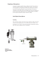
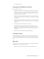
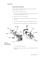
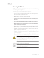
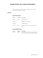
1
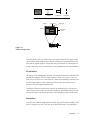
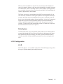
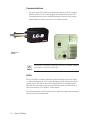
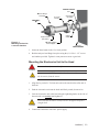
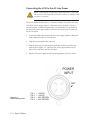
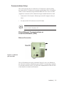
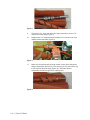
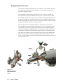
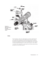
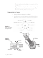
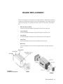
Dycor LC-D Residual Gas Analyzer User Manual Process Instruments 90548VE Rev. F 150 Freeport Road Pittsburgh, PA 15238 Offices USA - HEADQUARTERS AMETEK Process Instruments 150 Freeport Road Pittsburgh, PA 15238, USA Phone: 412-828-9040 Fax: 412-826-0399 USA - Delaware AMETEK Process Instruments 455 Corporate Boulevard Newark, Delaware 19702, USA Phone: 302-456-4400 (Main) 800-537-6044 (Service) 800-222-6789 (Ordering) Fax: 302-456-4444 USA - Texas AMETEK Process Instruments 4903 W. Sam Houston Pkwy North Suite A-400 Houston, Texas 77041, USA Phone: 713-466-4900 Fax: 713-849-1924 CANADA AMETEK Process Instruments 2876 Sunridge Way N.E. Calgary, Alberta Canada T1Y 7H9 Phone: 403-235-8400 Fax: 403-248-3550 GERMANY AMETEK GmbH Postfach 2165 D-40644 Meerbusch OR Rudolf-Diesel Strasse 16 D-40670 Meerbusch Germany Phone: 49-21-59-9136-0 Fax: 49-21-59-9136-39 SINGAPORE AMETEK Singapore PVT. Ltd. 10 Ang Mo Kio Street 65 #05-12 Techpoint Singapore 569059 Republic of Singapore Phone: 65-484-2388 Fax: 65-481-6588 FRANCE AMETEK - SAS Rond Point de l’épine des champs Buroplus Bat D 78990 Elancourt, France Phone: 33 1 30 68 89 20 Fax: 33 1 30 38 89 29 CHINA AMETEK Process Instruments Room 408, Metro Tower No. 30 Tian Yao Qiao Road Shanghai, 200030 Phone: 8621 6426 8111 Fax: 8621 6426 7818 © 2007 AMETEK This manual is a guide for the use of the Dycor LC-D Residual Gas Analyzer. Data herein has been verified and validated and is believed adequate for the intended use of this instrument. If the instrument or procedures are used for purposes over and above the capabilities specified herein, confirmation of their validity and suitability should be obtained; otherwise, AMETEK does not guarantee results and assumes no obligation or liability. This publication is not a license to operate under, or a recommendation to infringe upon, any process patents. ii | Dycor LC-D Series Table of Contents CHAPTER 1 OVERVIEW LC-D Analyzer.................................................................................... 1-1 LC-D System 200 Software................................................................ 1-1 Mass Spectrometer Theory.................................................................................. 1-2 Sampling System................................................................................ 1-2 Mass Spectrometer Hardware............................................................. 1-2 Ionization...................................................................................... 1-2 EI Ionization.................................................................................. 1-3 Separation..................................................................................... 1-4 Detection....................................................................................... 1-4 Data System........................................................................................ 1-5 LC-D Configuration............................................................................................. 1-6 LC-D................................................................................................... 1-6 Communications................................................................................. 1-6 LEDs................................................................................................... 1-7 CHAPTER 2 SPECIFICATIONS CHAPTER 3 INSTALLATION Mechanical Installation........................................................................................ 3-2 Connecting the Head to the Vacuum System...................................... 3-2 Mounting the Electronics Unit to the Head........................................ 3-3 Connecting the LC-D to the AC Line Power...................................... 3-4 Communications Setup........................................................................................ 3-5 Direct Ethernet Communications . .................................................... 3-5 Local Area Network (LAN)................................................................ 3-5 Ethernet Connection..................................................................... 3-5 LEDs.................................................................................................................... 3-6 CPU..................................................................................................... 3-6 Comm.................................................................................................. 3-6 RF...................................................................................................... 3-6 Filament.............................................................................................. 3-6 Capillary Inlet Heater Option.............................................................................. 3-7 CHAPTER 4 SAMPLING SYSTEMS Sampling Under Vacuum..................................................................................... 4-2 Inlets.................................................................................................................... 4-3 Sampling at Atmosphere...................................................................................... 4-5 Inlet Option Descriptions.................................................................... 4-5 Capillary....................................................................................... 4-5 Aperture........................................................................................ 4-6 | iii Sweep tee....................................................................................... 4-6 High conductance valve................................................................ 4-6 Pumping Systems................................................................................................. 4-7 High Vacuum Pumping Systems......................................................... 4-7 Model VPS70 pumping system...................................................... 4-7 Model VPS70D dry pumping system............................................. 4-7 CHAPTER 5 MAINTENANCE AND TROUBLESHOOTING Analyzer Head Maintenance................................................................................ 5-2 Filaments.............................................................................................................. 5-2 Equipment required to replace a filament..................................... 5-2 Removing the LC-D electronics from the head............................. 5-3 Replacing the filament................................................................... 5-3 Disassembling the Source.................................................................................... 5-5 Assembly and Installation of the Source............................................ 5-5 Cleaning the Source............................................................................ 5-5 Mass Filter.......................................................................................... 5-6 Electron Multiplier ............................................................................................. 5-6 Mounting the Head on the AMETEK Vacuum Chamber.................................... 5-7 Troubleshooting the LC-D . ................................................................................ 5-8 Things to Check First.......................................................................... 5-8 Quick and Easy Solutions................................................................... 5-8 LC-D Communications and LEDs..................................................................... 5-10 Filament Trip/Overpressure and LEDs.............................................................. 5-11 Caution Against Swapping Components........................................................... 5-12 CHAPTER 6 BOARD REPLACEMENT Master Board....................................................................................................... 6-2 Control Board and Scan Board............................................................................ 6-3 Amp Card............................................................................................................. 6-5 RF Card................................................................................................................ 6-7 SPARE PARTS, ACCESSORIES, KITS Start-Up................................................................................................................ 6-9 Normal Operation............................................................................... 6-9 Normal Maintenance........................................................................... 6-9 LC-D Manifold Kits.......................................................................................... 6-10 Spare Analyzer Heads........................................................................................ 6-10 Accessories........................................................................................................ 6-11 LC-D Pumping Systems.................................................................................... 6-11 iv | Dycor LC-D Series Safety Notes warnings, cautions, and notes contained in this manual emphasize critical instructions as follows: An operating procedure which, if not strictly observed, may result in personal injury or environmental contamination. An operating procedure which, if not strictly observed, may result in damage to the equipment. Important information that should not be overlooked. NOTE Electrical Safety Up to 5 kV may be present in the analyzer housings. Always shut down power source(s) before performing maintenance or troubleshooting. Only a qualified electrician should make electrical connections and ground checks. Any use of the equipment in a manner not specified by the manufacturer may impair the safety protection originally provided by the equipment. Dymaxion Electronics and Sensor Before connecting the 24 VDC power to the electronics, ensure that the electronics are connected to the sensor. Otherwise, damage to the electronics is possible. Always remove 24 VDC power from the electronics before removing the electronics from the sensor. Cables and Wiring Use only shielded Category 5 cable. This is required to minimize electromagnetic interference and comply with the EMC Directive. Grounding Instrument grounding is mandatory. Performance specifications and safety protection are void if instrument is operated from an improperly grounded power source. Verify ground continuity of all equipment before applying power. | v Warning Labels These symbols may appear on the instrument in order to alert you of existing conditions. Protective Conductor Terminal (BORNIER DE L’ECRAN DE PROTECTION) Schutzerde Caution - Risk of electric shock (ATTENTION-RISQUE DE DÉCHARGE ÉLECTRIQUE) Achtung - Hochspannung Lebensgefahr Caution - (Refer to accompanying documents) (ATTENTION-SE RÉFERER AUX DOCUMENTS JOINTS) Achtung (Beachten Sie beiliegende Dokumente) CAUTION - Hot Surface (ATTENTION-SURFACE CHAUDE) Achtung - Heiße Oberfläche Environmental Information (WEEE) This AMETEK product contains materials that can be reclaimed and recycled. In some cases the product may contain materials known to be hazardous to the environment or human health. In order to prevent the release of harmful substances into the environment and to conserve our natural resources, AMETEK recommends that you arrange to recycle this product when it reaches its “end of life.” Waste Electrical and Electronic Equipment (WEEE) should never be disposed of in a municipal waste system (residential trash). The Wheelie Bin marking on this product is a reminder to dispose of the product properly after it has completed its useful life and been removed from service. Metals, plastics and other components are recyclable and you can do your part by one of the following these steps: vi | Dycor LC-D Series • When the equipment is ready to be disposed of, take it to your local or regional waste collection administration for recycling. • In some cases, your “end-of-life” product may be traded in for credit towards the purchase of new AMETEK instruments. Contact your dealer to see if this program is available in your area. • If you need further assistance in recycling your AMETEK product, contact our office listed in the front of the instruction manual. Electromagnetic Compatibility (EMC) Read and follow the recommendations in this section to avoid performance variations or damage to the internal circuits of this equipment when installed in harsh electrical environments. The various configurations of the Dycor LC-D should not produce, or fall victim to, electromagnetic disturbances as specified in the European Union’s EMC Directive. Strict compliance to the EMC Directive requires that certain installation techniques and wiring practices are used to prevent or minimize erratic behavior of the Analyzer or its electronic neighbors. Below are examples of the techniques and wiring practices to be followed. In meeting the EMC requirements , the various Analyzer configurations described in this manual rely heavily on the use of metallic shielded cables used to connect to the customer’s equipment and power. Foil and braid shielded I/O and DC power cables are recommended for use in otherwise unprotected situations. In addition, hard conduit, flexible conduit, and armor around non-shielded wiring also provides excellent control of radio frequency disturbances. However, use of these shielding techniques is effective only when the shielding element is connected to the equipment chassis/earth ground at both ends of the cable run. This may cause ground loop problems in some cases. These should be treated on a case-by-case basis. Disconnecting one shield ground may not provide sufficient protection depending on the electronic environment. Connecting one shield ground via a 0.1 microfarad ceramic capacitor is a technique allowing high frequency shield bonding while avoiding the AC-ground metal connection. In the case of shielded cables the drain wire or braid connection must be kept short. A two-inch connection distance between the shield’s end and the nearest grounded chassis point, ground bar or terminal is highly recommended. An even greater degree of shield performance can be achieved by using metallic glands for shielded cable entry into metal enclosures. Expose enough of the braid/foil/drain where it passes through the gland so that the shield materials can be wrapped backwards onto the cable jacket and captured inside the gland, and tightened up against the metal interior. Inductive loads connected to the low voltage “Alarm Contacts” are not recommended. However, if this becomes a necessity, adhere to proper techniques and wiring practices. Install an appropriate transient voltage suppression device (low voltage MOV, “Transzorb,” or R/C) as close as possible to the inductive device to reduce the generation of transients. Do not run this type of signal wiring along with other I/O or DC in the same shielded cable. Inductive load wiring must be separated from other circuits in conduit by using an additional cable shield on the offending cable. In general, for optimum protection against high frequency transients and other disturbances, do not allow installation of this Analyzer where its unshieled I/O and DC circuits are physically mixed with AC mains or any other circuit that could induce transients into the Analyzer or the overall system. Examples of electrical events and devices known for the generation of harmful electromagnetic disturbances include motors, capacitor bank switching, storm related transients, RF welding equipment, static, and walkie-talkies. | vii PN EC Declaration of Conformity Manufacturer’s Name: AMETEK, Inc., Process Instruments (ISO 9001 Registered 1995) Manufacturer’s Address: Process & Analytical Instruments Division 150 Freeport Road Pittsburgh, PA, 15238 USA Phone: 412-828-9040 Fax: 412-826-0686 declares that the product: Product Name: Dycor LC-D Residual Gas Analyzer Model Number(s): LCD100 100 AMU LCD100M 100 AMU Multiplier LCD200 200 AMU LCD200M 200 AMU Multiplier LCD300 300 AMU LCD300M 300 AMU Multiplier complies with the requirements of EMC Directive 2004/108/EC: EN 61326-1 Radio Frequency Emissions EN50011 (CISPR 11) Radiated and Conducted, Class A, Group 2, ISM Device EN61000-3-2 Harmonic Current EN61000-3-3 Voltage Fluctuation / Flicker EN61326-1, / EN50082-1 Immunity EN61000-4-2 Electrostatic Discharge, 4kV/8kV, contact/air EN61000-4-3, ENV50204 Radiated Radio Frequencies, 3V/m EN61000-4-4 Electrical Fast Transient/Burst, .5kV/1kV EN61000-4-5 Surge, 1kV to Shields, 1kV/2kV AC Differential/Common EN61000-4-6 Conducted Radio Frequencies, 3 V/m EN61000-4-8 Magnetic Immunity EN61000-4-11 Voltage Dips and Variations, 100%, 95%, 60% and 30% and with the low voltage directive 2006/95/EC: EN 61010-1, Safety Requirement for Electrical Equipment Manufacturer’s Address in Europe: AMETEK Precision Instruments Europe GmbH Rudolf-Diesel-Strasse 16 D-40670 Meerbusch Germany Contact: Dr. Jurgen Gassen viii | Dycor LC-D Series WARRANTY AND CLAIMS We warrant that any equipment of our own manufacture or manufactured for us pursuant to our specifications which shall not be, at the time of shipment thereof by or for us, free from defects in material or workmanship under normal use and service will be repaired or replaced (at our option) by us free of charge, provided that written notice of such defect is received by us within twelve (12) months from date of shipment of portable analyzers or within eighteen (18) months from date of shipment or twelve (12) months from date of installation of permanent equipment, whichever period is shorter. All equipment requiring repair or replacement under the warranty shall be returned to us at our factory, or at such other location as we may designate, transportation prepaid. Such returned equipment shall be examined by us and if it is found to be defective as a result of defective materials or workmanship, it shall be repaired or replaced as aforesaid. Our obligation does not include the cost of furnishing any labor in connection with the installation of such repaired or replaced equipment or parts thereof, nor does it include the responsibility or cost of transportation. In addition, instead of repairing or replacing the equipment returned to us as aforesaid, we may, at our option, take back the defective equipment, and refund in full settlement the purchase price thereof paid by Buyer. Process photometric analyzers, process moisture analyzers, and sampling systems are warranted to perform the intended measurement, only in the event that the customer has supplied, and AMETEK has accepted, valid sample stream composition data, process conditions, and electrical area classification prior to order acknowledgment. The photometric light sources are warranted for ninety (90) days from date of shipment. Resale items warranty is limited to the transferable portion of the original equipment manufacturer’s warranty to AMETEK. If you are returning equipment from outside the United States, a statement should appear on the documentation accompanying the equipment being returned declaring that the goods being returned for repair are American goods, the name of the firm who purchased the goods, and the shipment date. The warranty shall not apply to any equipment (or part thereof) which has been tampered with or altered after leaving our control or which has been replaced by anyone except us, or which has been subject to misuse, neglect, abuse or improper use. Misuse or abuse of the equipment, or any part thereof, shall be construed to include, but shall not be limited to, damage by negligence, accident, fire or force of the elements. Improper use or misapplications shall be construed to include improper or inadequate protection against shock, vibration, high or low temperature, overpressure, excess voltage and the like, or operating the equipment with or in a corrosive, explosive or combustible medium, unless the equipment is specifically designed for such service, or exposure to any other service or environment of greater severity than that for which the equipment was designed. The warranty does not apply to used or secondhand equipment nor extend to anyone other than the original purchaser from us. THIS WARRANTY IS GIVEN AND ACCEPTED IN LIEU OF ALL OTHER WARRANTIES, WHETHER EXPRESS OR IMPLIED, INCLUDING WITHOUT LIMITATION AND WARRANTIES OF FITNESS OR OF MERCHANTABILITY OTHER THAN AS EXPRESSLY SET FORTH HEREIN, AND OF ALL OTHER OBLIGATIONS OR LIABILITIES ON OUR PART. IN NO EVENT SHALL WE BE LIABLE UNDER THIS WARRANTY OR ANY OTHER PROVISION OF THIS AGREEMENT FOR ANY ANTICIPATED OR LOST PROFITS, INCIDENTAL DAMAGES, CONSEQUENTIAL DAMAGES, TIME CHANGES OR ANY OTHER LOSSES INCURRED BY THE ORIGINAL PURCHASER OR ANY THIRD PARTY IN CONNECTION WITH THE PURCHASE, INSTALLATION, REPAIR OR OPERATION OF EQUIPMENT, OR ANY PART THEREOF COVERED BY THIS WARRANTY OR OTHERWISE. WE MAKE NO WARRANTY, EXPRESS OR IMPLIED, INCLUDING WITHOUT LIMITATION ANY WARRANTIES OF FITNESS OR OF MERCHANTABILITY, AS TO ANY OTHER MANUFACTURER’S EQUIPMENT, WHETHER SOLD SEPARATELY OR IN CONJUNCTION WITH EQUIPMENT OF OUR MANUFACTURE. WE DO NOT AUTHORIZE ANY REPRESENTATIVE OR OTHER PERSON TO ASSUME FOR US ANY LIABILITY IN CONNECTION WITH EQUIPMENT, OR ANY PART THEREOF, COVERED BY THIS WARRANTY. | ix This page intentionally left blank. x | Dycor LC-D Series Overview Dycor LC-D Residual Gas Analyzer The Dycor LC-D is a compact quadrupole mass spectrometer primarily used as a residual gas analyzer. The LC-D offers the most cost-effective solution to process monitoring needs. LC-D Analyzer The standard configuration LC-D residual gas analyzer consists of the following components: • Open ion source quadrupole mass spectrometer analyzer head in 100, 200 or 300 AMU range, and electronics unit. • Faraday cup detector or Faraday cup with microchannel plate electron multiplier. System 200 LC-D Software Integrated System 200 LC-D Software that provides: • variety of operating modes including Analog and Bar, Meter, Annunciator, Tabular, Trend, and Leak Detection, • auto-tune capabilities, • Dynamic Data Exchange (DDE) automation for limited control by Windows applications, • customized displays, and • single or continuous scan with user-defined interval. Overview | 1-1 Mass Spectrometer Theory The mass spectrometer allows you to identify the masses of individual atoms and molecules that have been converted to ions from a given sample. This technique is unique in that it provides a fingerprint identification for the structural and chemical properties of these molecules. The quadrupole mass spectrometer is one of a specialized subset of mass spectrometers that measure background gases in an existing vacuum chamber. A mass spectrometer consists of the following components: • Sampling System • Mass Spectrometer Hardware • Data System Sampling System The Sampling System serves as a connection between the outside sample environment and the vacuum environment that the mass spectrometer requires. The Dycor LC-D can be equipped with a variety of inlet systems. All of these systems are configured to bring the required number of sample streams into the LC-D at the specified pressure, while maintaining the high vacuum necessary for proper mass spectrometry operation. Mass Spectrometer Hardware Once the sample reaches the mass spectrometer hardware, three processes take place: • Ionization • Separation • Detection Ionization During ionization, sample molecules are turned into ions which are then focused towards the quadrupole to be detected. The process occurs in the ionizer which consists of a filament, filament electron repeller, source grid, and focus plate. See Figure 1-1. The filament produces electrons. As current flows through the filament, it is electrically heated to incandescence and emits free electrons. Once the electrons are free, they are accelerated towards the source grid by the potential difference between the filament and the source grid. As a cloud of electrons accelerates towards the source grid, the electrons collide with the sample and create ions. 1-2 | Dycor LC-D Series repeller Source Grid Filament repeller Source Grid Filament Focus Plate Focus Plate Top Alumina Collar .. .. .. .. .. Figure 1-1. Ionizer components. Mass Filter Once the positive ions are formed, they are extracted from the ion region and focused towards the quadrupole mass filter by a difference in potential. This focus plate has an applied negative voltage that, due to a difference in electrostatic potential, attracts the newly formed positive ions, passing them into the quadrupole. EI Ionization The energy of the bombarding electrons is much greater than the bonds that hold the molecule together. When a single electron is removed, a positive ion is created - this is referred to as a molecular ion. When the bombarding electrons cause the molecular bonds to break, fragment ions form. This ionization process is known as electron impact ionization (EI). Operation of the mass spectrometer depends on maintaining low vacuum pressures. These pressures take into account not only the operational pressures of the mass spectrometer, but also the pressures of the sampling system environments. Separation Once the ions reach the quadrupole mass filter, they are filtered according to their mass-to-charge (m/z) ratio. Each ion has an identifiable mass. The quadrupole Overview | 1-3 mass filter is constructed of four electrically-conducting, parallel cylindrical rods. A constant direct current (DC) voltage and an alternating radio-frequency (RF) voltage is applied along the length of the rods. Through proper electronic tuning, these voltages set the criteria for the ions that pass through the quadrupole. As an ion enters the quadrupole mass filter, the RF and DC fields cause it to undergo oscillations. Depending upon the criteria set for motion through the quadrupole, an ion passes through the quadrupole where it is neutralized on the walls of the vacuum housing. Ions meeting the m/z criteria have stable trajectories and emerge from the mass filter assembly (Figure 1-2). Ions with other m/z values have unstable trajectories and are neutralized as they strike the walls of the vacuum housing. Ions that successfully pass through the quadrupole are again focused towards the detector using an exit aperture which has an applied negative voltage that attracts the positively charged ions. Detection The simplest detection setup consists of a Faraday cup detector. An electron multiplier is used for amplified sensitivity. A Faraday cup detector is a closed structure except for an opening that allows the ions to enter. As the positive ions exit the quadrupole mass filter, they strike the detector, creating a current. This current is then sent to the preamplifier for amplification and then to the data system for display. Exit Lens Quadrupole Focus Lens + Ionization Chamber + + + + - + DC Figure 1-2. Quadrupole mass filter. 1-4 | Dycor LC-D Series + + + + + - DC Detector When an electron multiplier is used, the ions are attracted to the multiplier because of its negative charge. As the ions strike the multiplier, secondary electrons are emitted. This creates a cascading effect as each secondary electron generates more secondary electrons as they move down the multiplier wall, amplifying the signal by approximately one thousand. The Dycor system uses a microchannel plate (MCP) electron multiplier. It consists of an array of millions of small glass capillaries fused together in the shape of a disk. The inside wall of each channel has a resistive, electrically semi-conductive layer, forming independent electron multipliers. As the ions are approaching the MCP, a positive electrical gradient pulls the electrons into the MCP. As they cascade down and strike the channel walls, they generate secondary electrons. The Dycor MCP has the advantage in that it is stable and is especially beneficial for detection of low-level species. Data System Overall control of the system, acquisition of data, and access to collected data is accomplished through the Dycor System 200 software. Adjustment of all instrument parameters that affect sampling, ionization, separation and detection are software controlled. All data acquisition parameters are also set using the software. LC-D Configuration LC-D The LC-D (Figure 1-3) is available in 100, 200 or 300-AMU ranges using a Faraday cup or optional channel plate multiplier detector. Overview | 1-5 Communications • The System 200 LC-D software communicates directly to the PC using an Ethernet crossover CAT-5 cable plugged into an Ethernet port on the PC. Communication can also be established through a network (LAN) using a standard Ethernet cable between the LC-D and the network. Figure 1-3. LC-D An Ethernet card must be installed in your PC to establish communication between the LC-D and the PC. NOTE LEDs The LC-D LEDs are located on the back of the electronics as shown in Figure 1-3. When first started, the LC-D cycles through the LEDs, turning them green, red and yellow. This allows you to check that each LED is working properly. When the unit is through cycling, the top LED turns green. For further help on LED error messages, see Chapter 6 of this manual. The LEDs that follow are listed in the order in which they appear (top to bottom) on the back of the electronics unit. 1-6 | Dycor LC-D Series CPU Indicates CPU and system status. • OFF • RED • FLASHING RED LC-D power is off. CPU has stopped. Battery-backed RAM has been cleared. Check battery. • GREEN Normal operation. Comm Shows the status of communications between the LC-D and the PC. It flashes green when receiving data from the PC. It remains off when the LC-D is inactive. A red light indicates a communications error. RF Shows the status of the RF circuit. The LED is green if the RF amplifier is operating properly, and turns red if there is an RF failure. The LED is yellow during automatic RF tune. NOTE If you are having a problem in this area contact your service engineer. Filament Indicates the status of the filament. The LED is green if the filament is on and is working properly. The LED appears red if the filament is off because of an overpressure, open or short condition. The LED appears yellow if half of the filament has failed. Overview | 1-7 This page intentionally left blank. 1-8 | Dycor LC-D Series LC-D SPECIFICATIONS Mass Range: 1 - 100 AMU standard; 1-200 and1-300 AMU optional Operating Pressure Range: 10 -4 Torr to ultrahigh vacuum Minimum Detectable Partial Pressure: 5 x 10 -12 Torr (5 x 10 -14 Torr for electron multiplier units) Resolution: Adjustable to constant peak width (0.5 AMU at 10% height) Emission Current: 0.1 to 10 mA; 50 mA to degas Electron Energy: 30 to 150 volts to operate; 200 volts to degas Specifications | 2-1 Ion Energy: 1 to 10 volts Source Sensitivity (Faraday Cup): 2 x 10 -4 amps per Torr at detector (measured with nitrogen at mass 28 with peak width = 0.5 at 10% height and 1 x 10 -3 amps emission current) Power Requirements: 24VDC @ 3.2 Amps; 110/120 VAC, 50/60 Hz adaptor available Stability: Mass stability: ± 0.1 AMU after 30-minute warm-up; Peak Height: ± 2% per 5 hours after 30-minute warm-up. Ethernet Connectivity: 10/100BASE-T Ethernet - Auto-Sensing; RJ-45 connector NOTE Always use a shielded Category 5 cable for Ethernet connections. This is required to minimize electromagnetic interference. Physical Dimensions: Weight: Width: Length: Height: 2-2 | Dycor LC-D Series 4.6 lb 7.4 lb 4.5 in. 9.0 in 5.25 in (2.1 kg) without quad head (3.4 kg) with quad head (11.4 cm) (22.9 cm) (13.3 cm) Installation This chapter contains information on the installation and initial operation of the LC-D system including the following: • Mechanical installation • Communications setup • LEDs Dymaxion Electronics and Sensor Before connecting the 24 VDC power to the electronics, ensure that the electronics are connected to the sensor. Otherwise, damage to the electronics is possible. Always remove 24 VDC power from the electronics before removing the electronics from the sensor. Installation | 3-1 Mechanical Installation If you are not familiar with high vacuum systems and procedures and with handling the analyzer head to prevent contamination, refer to Chapter 6 of this manual for proper handling procedures before continuing. The LC-D is shipped wrapped in a protective covering. Check all parts to ensure that nothing has been damaged. If you discover damage, report it to the factory immediately. 1. Install the sensor assembly into vacuum system. 2. Attach the LC-D electronics to the analyzer head. 3. Connect the LC-D electronics to 24 VDC power. NOTE If the analyzer is a 230-Volt type, the power cord plug must be changed to the proper type to match your country and/or electrical code. Connecting the Head to the Vacuum System NOTE The head is already assembled andconnected to the AMETEK vacuum system at the factory. Instructions for mounting the head to an alternate vacuum system are provided below. Mounting the head to a vacuum chamber 1. Using a new copper gasket, fasten the stainless steel shipping nipple to the vacuum chamber with (6) ¼-28 x 1” screws or bolts and nuts. 2. Using a new copper gasket, install the head into the nipple so that the repeller clears the chamber walls. 3-2 | Dycor LC-D Series Customer 2 3/4 CF Port Detector Flange Assembly (6) 1/4-28 Screw s Open Source Assembly Barrel Notch Up Copper Gasket (not show n) Figure 3-1. Mounting the head to a vacuum chamber. Copper Gasket AMETEK-Supplied Vacuum Nipple Customer Vacuum Chamber 3. Orient the barrel notch in the 12 o’clock position. 4. Bolt the analyzer head flange into place using the (6) ¼-28 x 1-1/2” screws and washers provided. Tighten in a star pattern to ensure a good seal. Mounting the Electronics Unit to the Head Power to the analyzer must be off. Always remove 24 VDC power from the electronics before removing the electronics from the sensor. 1. Align the key on the LC-D electronics unit to the notch on the collar end of the head. 2. Push the electronics unit onto the head until firmly seated (do not twist). 3. Lock the electronics unit to the head using the tightening knobs on the side of the unit until it is securely hand-tightened. Never twist the electronics. Always insert it straight in and pull it straight back. 4. Connect the electronics unit to the power supply. Installation | 3-3 Connecting the LC-D to the AC Line Power Before connecting the 24 VDC power to the electronics, ensure that the electronics are connected to the sensor. Otherwise, damage to the electronics is possible. The LC-D requires 24 Volts DC (± 1 Volt) and 3.2 Amps. If you have your own 24-Volt DC power supply, Figure 3-2 shows the pinouts for the LC-D powerinput connection. A braided, shielded cable is recommended. If you purchased the Dycor DC power supply module, follow the directions below to connect to the AC line power. 1. Connect the DIN connector from the DC power supply module to the power input connection on the LC-D electronics . 2. Align the key and push in the connector. 3. Push the outer ring over the connector and rotate clockwise until the ring locks in place (Figure 3-2). The Dycor DC power supply model accepts either 110 or 220 Volts, 50/60 Hz AC input. 4. Plug the DC power supply module into the appropriate AC power outlet. POWER INPUT KEY Figure 3-2. Power input pinouts. 3-4 | Dycor LC-D Series PIN PIN PIN PIN 1 2 3 4 = = = = +24VDC +24VDC 24V RETURN 24V RETURN Communications Setup This section describes how to connect the LC-D analyzers to the PC running the System 200 LC-D software to accept the incoming data. The LC-D supports either a a direct connection using an shielded Ethernet CAT-5 cross-over cable (supplied) or a network (LAN) connection using an installed network or a hub. • Connect the LC-D electronics Ethernet port to the PC using the cable provided. • Use System 200 LC-D software to read LC-D data. NOTE An Ethernet card must be installed in the PC to allow communication between the LC-D and the PC. Direct Ethernet Communications or Local Area Network (LAN) Ethernet Connection LEDs Ethernet Port Heat Sink Figure 3-3. Ethernet port and LEDs. Power The LC-D Ethernet port requires a shielded Category-5 cross-over Ethernet cable. This cable connects to the Ethernet port on the PC. If connecting to multiple LC-Ds using a network (LAN), you will need a standard Ethernet cable for each of the analyzers to connect to the network. Installation | 3-5 LEDs The LC-D LEDs are located on the back of the electronics unit as shown in Figure 3-3. When first started, the LC-D cycles through the LEDs, turning them green, red and yellow. This allows you to check that each LED is working properly. When the unit is through cycling, the top LED turns green and then the third LED (RF) turns green as well. The LEDs are listed below in the order in which they appear (top to bottom) on the back of the electronics unit (Figure 3-3). CPU Indicates CPU and system status. • OFF • RED • FLASHING RED • GREEN LC-D power is off. CPU has stopped. Battery-backed RAM has been cleared. Check battery. Normal operation. Comm Shows the status of communications between the LC-D and the PC. It flashes green when receiving data from the PC. It remains off when the LC-D is inactive. A red light indicates a communications error. RF Shows the status of the RF circuit. The LED is green if the RF amplifier is operating properly, and turns red if there is an RF failure. The LED is yellow during automatic RF tune. NOTE If you are having a problem in this area contact your service engineer. Filament This LED indicates the status of the filament. The LED is green if the filament is on and is working properly. The LED appears red if the filament is off due to an overpressure, open or short condition. The LED appears yellow if half of the filament has failed. 3-6 | Dycor LC-D Series Capillary Inlet Heater Option Controller Settings SETUP SEn tc Lin H C-F C S.dEC 0 IS.En no SP.Lo 0 SP.hi 250 Ftr.E OFF Ot 1 hEAt Ctr1 Ftb Ftb1 5.0 PL 1 100.0 PSL1 0.0 PSH1 100.0 nLF1 OFF Ot 2 OFF Unit SI I.Err nLAt FAIL bPLS dSP Pro rP OFF LOC 0 OPERATIONS A-M Auto Aut OFF CAL 0 ht.M Pid Pb.ht 5 It.ht 14.87 dE.ht 0.61 Installation | 3-7 Installation Figure 1a Figure 1b Figure 1c 1. Unwrap the Velcro straps on the ends of the insulated heater jacket (Figures 1b and 1c) to expose the heater and inner tubing. 2. Gently feed the fused silica capillary tube through the Swagelok fittings and stainless steel tube until approximately 1 inch (2.54 cm) of capillary tube is exposed at each end (Figures 2a and 2b). Figure 2a Figure 2b Do not force the capillary tube into the steel fittings. If the capillary tube gets stuck, pull it back a few centimeters and then continue feeding it through. 3. 3-8 | Dycor LC-D Series Install a graphite ferrule on each exposed end of the capillary tube with the cone-shaped end of the ferrule facing away from the end of the capillary tube. Figure 3 4. Loosen one end of the 1/8” Swagelok tube fitting located at each end of the stainless steel tubing (Figure 3). 5. Feed the end of the capillary tube where the heater’s electrical connections are located into the valve end of the ProLine System (Figure 3). Figure 4 6. Tighten the 1/16” nut at the end of the heater assembly onto the 1/16” threaded stub of the ProLine (Figure 4) 7. Retighten the 1/8” Swagelok fitting located at the Proline side of the heater assembly (Figure 4). 8. Feed the remaining free end of the capillary heater assembly into the customer process fitting (Figure 5). Figure 5 Installation | 3-9 Figure 6 9. Tighten the 1/16” nut at the end of the heater assembly onto the 1/16” customer process fitting (Figure 6). 10. Retighten the 1/8” Swagelok fitting located on the customer side of the capillary heater assembly (Figure 6). Figure 7 11. Make sure the spiral stretch-to-length heater covers all the tubing and fittings, beginning at the ProLine valve stub (Figure 7a) and continu¬ing to the customer process fitting (Figure 7b). The heater should encapsulate the entire length of the capillary tube. Figure 8 3-10 | Dycor LC-D Series Figure 9 12. Close up the insulated heater jacket. The jacket should extend approx¬imately 1 inch (2.54cm) onto the ProLine valve stub and 1 inch (2.5cm) onto the customer fitting. Replace the Velcro straps (Figure 8). 13. Install the stainless steel tube clamps at each end of the heater jacket (Figure 9). Figure 10 14. Plug the thermocouple wire and heater power cord into the ProLine electronics box (Figure 10). 15. The capillary tube heater will turn on when the ProLine is turned on. It takes approximately 30 minutes to reach temperature. Figure 11 Installation | 3-11 This page intentionally left blank 3-12 | Dycor LC-D Series Sampling Systems There are a variety of ways to introduce gas samples to the mass spectrometer. The sampling system serves as a bridge between the sample environment and the vacuum environment of 10-4 to 10-9 Torr required by the mass spectrometer. If a sample is at the same operating pressure as the mass spectrometer, the sample can be analyzed directly. However, when the sample environment pressure is greater than 10-4 Torr, a pressure reduction sampling system is required. This chapter includes information on: • Sampling under vacuum • Inlets • Sampling at atmosphere • Inlet option descriptions • Pumping systems Sampling System | 4-1 Sampling Under Vacuum If the sample environment total pressure is less than 10-4 Torr, the mass spectrometer can be directly fitted into the sampling environment without an inlet with a differential pumping system. If the sampling environment is greater than 10-4 Torr, an inlet is required. For these applications, a high conductance inlet (Figures 4-1 and 4-2) can be fitted to the sample chamber. This inlet consists of a length of tubing installed between the sample chamber port and the mass spectrometer. Connection of the high conductance inlet makes it possible for the LC-D to sample from the sample chamber without being directly fitted to the sample chamber. When the pressure in the sampling chamber is greater than 10-4 Torr (but below atmospheric pressure), the high conductance valve is closed tightly and the aperture inlet is opened. The aperture inlet consists of a small aperture within a valve that connects the sampling system to the vacuum environment of the mass spectrometer. The aperture inlet should be opened slowly to evacuate the bypass arm. Once this volume has been evacuated, the pressure in the test chamber, the diameter of the aperture, and the pumping speed determine the pressure of the LC-D . Aperture diameters and their corresponding sample chamber pressures are provided in Figure 4-3. Manual Aperture Bypass Valve Inlet To Process Aperture Manual High Conductance Valve Figure 4-1 . High conductance inlet with manual valves. 4-2 | Dycor LC-D Series et g Jack Heatin Aperture To Process Vent to Pump or Exhaust Electropneumatic Sweep Tee Valve Inlet Solenoid Valve To Process Solenoid Valve Figure 4-2 . High conductance inlet with electropneumatic valves. To Air Supply 70 PSIG Electroneumatic High Conductance Valve Inlet Electropneumatic Aperture Bypass Valve Inlet Inlets The LC-D offers a wide variety of inlet options to suit many applications. The sensor manifold can support up to three different inlets at one time, reducing the amount of time spent breaking vacuum and changing fittings. All inlets are physically interchangeable on the same sensor manifold so they can be upgraded or replaced without disturbing the rest of the system. Figures 4-1 and 4-2 show two possible inlet configurations: one has manual valves and the other all electropneumatic valves for remote operation. Sampling System | 4-3 aperture Size pressure Ratio (Microns) Figure 4-3. Pressure reduction ratios for aperture inlet diameters. max. Sample Chamber Pressure (Torr) 2 6.0 x 10⁷ 600 5 1.0 x 10⁷ 100 10 2.5 x 10⁶ 25 20 6.0 x 10⁵ 6 50 1.0 x 10⁵ 1 100 2.5 x 10⁴ .25 200 6.0 x 10³ 6.0 x 10⁻² 500 1.0 x 10³ 1.0 x 10⁻² 1000 2.5 x 10² 2.5 x 10⁻³ No Aperture 70 7.0 x 10⁻⁴ Mathematically, aperture size and sample chamber pressure are clearly related through the equation below. This relationship calculates the diameter of the aperture needed to maintain a pressure of 10-5 Torr in the quadrupole region. Aperture Size (microns) = 50/(sample chamber pressure) .5 4-4 | Dycor LC-D Series Sampling at Atmosphere Atmospheric sampling is possible using a capillary tube inlet. The gas inlet is a fused silica capillary. The diameter and length of the capillary can be changed to accommodate specific applications, but any adjustments must meet the 10-5 Torr pressure requirement inside the vacuum system of the LC-D. The low conductance of the capillary decreases the sample gas pressure from atmospheric pressure to the pressure required by the LC-D. A heated capillary is available to prevent sample condensation desorption within the capillary. Inlet Option Descriptions Capillary This inlet delivers sample to the analyzer using a small-bore capillary with an ID tailored to suit the sample pressure. It is available with either a manual or electropneumatic valve. Figure 4-4 shows the manual and electropneumatic capillary inlets. These can be mounted on any LC-D manifold. Electropneumatic Valve Solenoid Valve Figure 4-4. Electropneumatic and manual capillary valves. Sampling System | 4-5 Aperture This inlet allows a high pressure sample to be delivered right to the analyzer. Its effective pressure is reduced by using a very small diameter aperture. The sample is switched on using the manual or electropneumatic valves. Sweep tee This inlet is similar to the aperture inlet except that an upstream tee fitting is installed to provide fresh sample to the analyzer aperture at all times. The sample is flushed past the aperture valve as a result of a pressure drop in the sample line. A vacuum pump creates the pressure drop for sub-atmospheric sampling. High conductance valve This valve allows the analyzer to be attached to a high vacuum process. The large bore of the valve permits good molecular flow to the analyzer. Installing one of the inlets will allow sampling from higher pressure samples after the high conductance valve is closed. 4-6 | Dycor LC-D Series Pumping Systems Pressure/vacuum levels required by the mass spectrometer are achieved by using a pumping system when the sample chamber is operating above 10-4 Torr (Figure 4-5). These pumping systems are application-dependent. Each system has a 70 l/sec (liter/second) turbomolecular pump that is connected directly to the inlet manifold. The turbomolecular pump can be backed by a rotary vane mechanical pump. This provides a 10-3 Torr pumping capacity that brings the system into a vacuum range in which the turbomolecular pump can operate. Using the two pumps together achieves a final operating vacuum of around 10-7 Torr. Rotary vane pumps are durable and inexpensive. For applications that require an ultra-clean environment, a diaphragm (dry system) is used in place of a conventional rotary vane pump. The diaphragm eliminates the possibility of oil contamination. High Vacuum Pumping Systems Model VPS70 pumping system Includes the turbomolecular pumping station with 70 l/s compound with 1.4 CFM roughing pump, compactly packaged in a steel frame. Model VPS70D dry pumping system Includes a turbomolecular pumping station with 70 l/s compound, with 0.42 CFM diaphragm roughing pump, compactly packaged in a steel frame. To be used where an oil-free pumping station is needed. Sampling System | 4-7 This page intentionally left blank. 4-8 | Dycor LC-D Series Maintenance and Troubleshooting This section includes information on: • • • • • • • maintaining the analyzer head, changing the filament, disassembling the source, cleaning the source reassembling the source cleaning the electron detector. troubleshooting the LC-D The rest of the LC-D system should require no routine maintenance during normal use. Disconnect all power from the analyzer before starting these procedures. Touching any part of the source or mass filter with your fingers will leave dirt and oil on the parts resulting in contamination of the head. Use clean plastic/latex gloves when handling components. Dymaxion Electronics and Sensor Before connecting the 24 VDC power to the electronics, ensure that the electronics are connected to the sensor. Otherwise, damage to the electronics is possible. Always remove 24 VDC power from the electronics before removing the electronics from the sensor. Maintenance & Troubleshooting | 5-1 Analyzer Head Maintenance • The analyzer head requires periodic maintenance. This maintenance can be performed by anyone familiar with vacuum system standard practices. • The entire head can be disassembled with the exception of the mass filter subassembly. Most parts can be replaced if necessary. • As the head is used, deposits will form on the source parts and on the mass filter. The lifetime of the source parts varies with application, exposure time, and vacuum pressure. Do not place the mass filter in an ultrasonic cleaner. The filter parts can become loose during ultrasonic cleaning. This will significantly degrade analyzer performance. A loosened mass filter must be replaced. Filaments The Dycor source contains a dual-wire filament so the analyzer can continue to function if one side of the filament burns out. The replacement filament comes in a protective container and can easily be replaced in the field. Equipment required to replace a filament • needle nose pliers, • 1/16” hex wrench (supplied by AMETEK/Dycor), • filament assembly kit (supplied by AMETEK/Dycor), • latex gloves - powder-free (optional). NOTE 5-2 | Dycor LC-D Series Handling the filament by the shorting tabs on the filament plate will ensure against contamination through handling since these tabs will eventually be discarded. Removing the LC-D electronics from the head Always remove 24 VDC power from the electronics before removing the electronics from the sensor. • After powering down the LC-D , carefully use the tightening knobs on the sides of the electronics unit to unlock the electronics from the head. • Once loosened, gently pull straight back on the electronics , without twisting, until it is free of the head. Do not remove the cabling from the electronics. Replacing the filament 1. Remove the six (6) ¼-28 bolts that fasten the head 10-pin feedthrough to the vacuum system. 2. Remove and discard the copper gasket. DO NOT TRY TO REUSE THE GASKET. 3. Position the head so that it is pointing up and is secure. Removing the old filament The filament plate is held in place by two (2) stainless steel rods that carry the current to the filament. Using the hex wrench provided, loosen the two small set screws on the barrel connectors that hold these rods in place, and slide the rods out of the head. Be sure to remove all residual pieces of the old filament. 1. Install the new filament being careful not to bend or break the delicate filament wires. Handle only the shorting tabs on the filament plate. 2. Tighten the set screws that hold the new filament in place. 3. Remove the shorting tabs on the filament by gently bending them back and forth with needle nose pliers until the tabs break at the notches at their bases. 4. Install a new copper gasket on the analyzer head feedthrough flange. Be sure it remains centered on the flange as the head is installed into the vacuum system. 5. Tighten the bolts using a cross pattern to ensure proper tightening and a leaktight connection. The maximum torque required is 110 in-lb (9 ft-lb). 6. Check for electrical isolation between the feedthrough pins. Maintenance & Troubleshooting | 5-3 • The check should be performed on the pins on the atmosphere side of the unit (Figure 5-1). • The pins should be electrically isolated from each other and from ground. • There should be approximately one ohm continuous circuit between the filament Pins 3 and 8. They should be isolated from ground. Disassembling the Source • Remove the filament (see instructions in this chapter). • Loosen the set screws on the barrel connectors that hold the three leads coming down from the source elements. The repeller, source and focus plate can HEAD Figure 5-1. Analyzer head pinout, view of flange (atmosphere side). en Op Repeller ce ur So Barrel Connectors Figure 5-2. LC-D source. 1/10” Spacing Repeller r ilte sF as M 1/10” Spacing Filament Post 5-4 | Dycor LC-D Series Source Ceramic Collar Focus Plate Detector Flange Assembly now easily be removed. Assembly and Installation of the Source Refer to Figures 5-1 and 5-2. 1. Install the focus element first so that its long wire engages the correct barrel connector at #1 (Figure 5-1). The back surface of the focus plate should rest against the ceramic collar of the mass filter. Tighten the barrel connector set screw snugly but do not overtighten. 2. Install the source so that its plate is spaced about 0.1” above the focus plate with its long wire in the correct barrel connector at #10 (Figure 5-1). Tighten the connection. 3. Install the repeller so that its plate is spaced about 0.1” above the source grid with its long wire in the correct barrel connector #2 (Figure 5-1). Tighten the connection. 4. Install the filament as described earlier in this chapter. 5. Insert the head into the vacuum chamber and secure using the six bolts originally removed. Tighten the bolts using a cross pattern to ensure proper tightening and a leak-tight connection. The maximum torque required is 110 in-lb (9 ft-lb). 6. Check for electrical isolation between the feedthrough pins. Cleaning the Source Because of the delicate nature of the source’s construction, it is impractical to clean off any deposits that might be on the source. These deposits will cause the source to lose sensitivity and so the source must be replaced when these deposits occur. Mass Filter Deposits can form at the entrance to the mass filter rods when they are operated at high pressures or over a long period of time. • Deposits can sometimes be seen as discolorations on the metal. In some Maintenance & Troubleshooting | 5-5 atmospheres, the rods might be coated with an invisible layer that will keep the mass filter from operating properly. This will result in a loss of sensitivity over the full range of the spectrum. If the peaks disappear at high scan speeds, an insulating layer may have developed on the surface of the rods. • Unless the nature of these discolorations can be identified exactly, the only sure way of removing them is with a fine abrasive. • The entire analyzer head assembly must be taken apart to clean the rods. We recommend that the head assembly be returned to the factory where the rods can be cleaned properly. NOTE Electron Multiplier The multiplier is immune to up-to-air cycling and routine low-level ion bombardment. However, over time the system will begin to lose gain. When this becomes unacceptable, a new multiplier will restore the original gain of the system. NOTE Call AMETEK Process Instruments or your local representative to arrange for factory service to replace the multiplier. Because of the complexity of the head assembly, we recommend that the multiplier be replaced at the factory. Mounting the Head on the AMETEK Vacuum Chamber The analyzer head is mounted to the AMETEK vacuum chamber at the factory before shipment. If you have to re-mount the head, follow these instructions. 1. Using a new copper gasket, install the head into the AMETEK vacuum chamber so that it resides inside the long end of the chamber. Be sure the repeller clears the chamber walls. 5-6 | Dycor LC-D Series 2. Orient the barrel notch in the 12 o’clock position. 3. Bolt the head flange in place using the (6) ¼-28 x 1” screws and washer provided. Tighten in a star pattern to ensure a good seal. 4. Install the appropriate inlet components to the analyzer head end of the vacuum chamber if they are not already installed. These consist of a ¾” thick VCR flange, a blank flange, a manual high-conductance valve or electropneumatic (EP) high-conductance valve, two copper gaskets, and fastener hardware. Inlet details can be found in the Chapter 5. Troubleshooting the LC-D Things to Check First In many cases, a system failure is not due to a problem with an electronic component, but rather to one of the following: • Operation at too high pressure (greater than 1 x 10⁻⁴ Torr). • Improper setting of parameters on a source or calibrate button. Detector Flange Assembly Barrel Notch Up Open Source Assembly Mass Filter Copper Gasket (6) 1/4-28 Screws AMETEK Vacuum Manifold Figure 5-3. Mounting the head to an AMETEK vacuum chamber. Maintenance & Troubleshooting | 5-7 • Incorrect or improper cable connection. • Burned out filament. • Shorted-out source parts usually resulting from an incorrect filament or source replacement. Quick and Easy Solutions The first step in providing a solution to the problem is performing the following checks. 1. Make sure the rod assembly is properly supported within the vacuum housing. 2. Check for leaks in the vacuum system. The system will not work properly (emission current control) if the vacuum system pressure is higher than 1 x 10⁻⁴ Torr. Power is automatically shut off from the unit above 2.5 x 10⁻³ Torr, if used with the AMETEK sensor manifold. 3. Make sure all cables are connected properly to the electronics unit. 4. Make sure that the electronics unit is fully pushed onto the feedthrough contacts. Reset the LC-D by unplugging the power cable from the electronics unit and plugging it back in. 5. Check the continuity between the filament feedthroughs. Although protected, the filament will eventually wear out. The best way to determine if this is the case is to check the filament continuity. − The check should be performed on the pins on the atmosphere side of the unit (Figure 5-4). − The pins should be electrically isolated from each other and from ground. − There should be approximately one ohm continuous circuit between the filament Pins 3 and 8. They should be isolated from ground. − If no continuity exists between Pins 3 and 8, remove the head from the vacuum system and replace the filament assembly. If the problem persists after going through these steps, you will have to localize the problem area. These potential problem areas are: 5-8 | Dycor LC-D Series • LC-D Communications and LEDs • Filament Trip/Overpressure and LEDs HEAD Figure 5-4. Analyzer head pinout, view of flange (atmosphere side). LC-D Communications and LEDs 1. Make sure the power supply cable between the LC-D and the power supply is plugged in at both ends. 2. Make sure the LC-D to PC Ethernet communications cable is secure. 3. Check the LEDs on the back of the electronics unit to make sure that all lights are green. The second light should be blinking green. Refer to “LED” section below for LED details. 4. If the problem persists, call the factory or your local manufacturer’s representative for assistance. The LEDs are listed below in the order in which they appear (top to bottom) on the back of the electronics unit. Maintenance & Troubleshooting | 5-9 CPU Indicates CPU and system status. • OFF: LC-D power is off. • RED: CPU has stopped. • FLASHING RED: Battery-backed RAM has been cleared. Check battery. • GREEN: Normal operation. Comm Shows the status of communications between the LC-D and the PC. It flashes green when receiving data from the PC. It remains off when the LC-D is inactive. A red light indicates a communications error. RF Shows the status of the RF circuit. The LED is green if the RF amplifier is operating properly, and turns red if you have an RF failure. The LED is yellow during automatic RF tune. NOTE If you are having a problem in this area please contact your service engineer. Filament This LED indicates the status of the filament. The LED is green if the filament is on and is working properly. The LED appears red if the filament is off due to an overpressure, open or short condition. The LED appears yellow if half of the filament has failed. Filament Trip/Overpressure and LEDs 1. Check the LEDs on the back of the electronics unit. Filament status can be determined by the color of the lights. Refer to the previous section for LED details. 2. Make sure the filament is turned on by checking the “Light Bulb” icon on the toolbar in the Dycor System 200 software to make sure it is yellow (ON). Check the filament status and emission current by cl;icking Edit on the toolbar and selecting Add Display. Click Head Status. 3. Restart the entire system and recheck the filament status and emission current. 4. If there is no filament current, turn off the analyzer, pull the electronics from the analyzer head and check the continuity between Pins 3 and 8. 5-10 | Dycor LC-D Series 5. If the filament is burned out (LED is red), open the vacuum system and replace the filament assembly. If the filament checks out OK, do the following: • Check the LEDs on the back of the electronics unit. • If the LEDs are green and there is no overpressure and the filament has not tripped, call the factory for assistance. Caution Against Swapping Components The Dycor System 200 software has been programmed to accept the combination of a head and electronics unit with different configurations and to automatically set a default configuration for the combined components. However, when mixing components with different configurations such as a multiplierelectronics unit and a Faraday cup head, the default configuration is always the Faraday cup configuration. • Do not mix components that come from different Dycor models. Maintenance & Troubleshooting | 5-11 This page left intentionally blank. 5-12 | Dycor LC-D Series Board Replacement The LC-D electronics unit contains five boards (Figure 6-1) that can be replaced in the field if damaged or found to be not working properly. These boards can be replaced using only a #1 Phillips screwdriver and a 1/4” nut driver. The boards are: Figure 6-1. LC-D board locations. • Ethernet Master Board Located on the left behind the front panel on the front of the unit. • Control Board Located behind the front heat sink and LED panel on the left side. • Scan Board Located behind the front heat sink and LED panel on the right side. • Amp Card Located behind the rear heat sink and under the Amp cover. • RF Board Located behind the rear heat sink and separated from it by the conductor guide. REAR FRONT Service and Parts | 6-1 Master Board The Master board is found behind the front panel of the LC-D electronics to the left of the heat sink (see Figure 6-1). Removing the Ethernet Master Board To remove the Ethernet Master board, follow these steps: 1. You must remove the entire front panel to access the Ethernet Master board. Remove the (3) 1/4” screws from the top and bottom of the unit and the 3/16” screws from the left and right side of the unit (see Figure 6-1). These screws hold the front panel in place. 2. Pull out the front panel. Attached are the Ethernet Master board, the Control board and the Scan board. Replacing the Ethernet Master Board 1. The Ethernet Master board is mounted to the front panel with a bracket. Disconnect the bracket from the front panel by removing the screws that hold it. 2. Next, remove the Ethernet Master board from the bracket. 3. Attach the Ethernet Master board replacement to the bracket and reattach the bracket to the inside of the front panel making sure that the connectors for all three boards are secure. 4. Replace the board assembly by inserting it into the electronics box and secure the front panel in place using the 1/4” screws for the top and bottom of the unit and the 3/16” screws for the sides. 6-2 | Dycor LC-D Series Control Board and Scan Board Removing the Control Board and the Scan Board The Control board and the Scan board are both located behind the front heat sink and the LED panel on the front panel. To remove the Control board or the Scan board, follow these steps: 1. Remove the 1/4” screws from the front top and bottom casing of the unit and the 3/16” screws from the sides. 3. Gently remove the board assembly from the unit casing. The Control board and the Scan board are both attached to the front panel under the heat sink. The Ethernet Master board is connected on the other side of the panel. 4. Once the assembly has been removed from the unit casing, remove the upper left and bottom right 3/8” screws with internal tooth lock washer from the heat sink. See Figure 6-1. 5. Gently pull on the front heat sink to remove it. The LED panel is now visible. 6. Remove the 1/4” screw from the bottom left of the LED panel to remove the Control board. Remove the 1/4” screw from the middle of the LED panel to remove the Scan board (Figure 6-1). 7. Gently pull the Control board or Scan board away from the adhesive gap pad on the back of the LED panel (Figure 6-2). Front Figure 6-2. Master, Control and Scan boards. Back Service and Parts | 6-3 Replacing the Control Board and Scan Board 1. Once the old board has been replaced and the new board attached to the front panel, for the Control board, attach the LED panel at the bottom left using the 1/4” screw. For the Scan board, attach the LED panel at the middle using the 1/4” screw. 2. Replace the front heat sink using the 3/8” screws and lock washers on upper left and bottom right. 3. Insert the board assembly into the unit making sure that the connectors for all three boards are secure. 4. Replace the board assembly by inserting it into the electronics box and secure the front panel in place using the 1/4” screws for the top and bottom of the unit and the 3/16” screws for the sides. NOTE 6-4 | Dycor LC-D Series There are adhesive gap pads on the back side of the front heat sink and the LED panel to ensure that all fixtures are secure and in place. Amp Card Removing the Amp Card The Amp Card is part of the RF assembly at the rear of the unit. It is located under the Amp cover. See Figure 6-3. To remove the Amp card, follow these steps: 1. There are eight screws holding the RF assembly in the unit casing. Remove the (3) top 1/4” and (3) bottom 1/4” screws. 2. Remove the (2) 3/16” screws from each side. 3. Grab hold of the rear heat sink and pull hard to remove the assembly from the casing. 4. You now have the complete RF assembly in your hand. Refer to Figure 6-3 5. Remove the Amp cover by removing the two 1/4” self-tapping sheet metal Al Oxide Insulator Amp Card Shield Amp Cover RF Card Conductor Guide Amp Card Shield Amp Card RF Card Amp Card Amp Cover Front Heat Sink Figure 6-3. Amp card and RF board replacement. screws. The Amp card is underneath. 6. Remove the Amp card by removing the (4) 1/4” screws holding it to the Amp card shield. Service and Parts | 6-5 Replacing the Amp Card 1. Secure the Amp card onto the Amp card shield using the (4) 1/4” screws. 2. Attach the Amp card cover to the Amp card using the two 1/4” self-tapping sheet metal screws. 3. Insert the RF assembly into the unit casing and secure using the (6) 1/4” screws for the top and bottom of the unit and the (2) 3/16” screws for the sides. 6-6 | Dycor LC-D Series RF Card Removing the RF Card The RF card is located directly behind the rear heat sink and separated from it by the conductor guide. See Figure 6-3. Follow these steps to remove the RF card for replacement: 1. There are eight screws holding the RF assembly in the unit casing. Remove the 3) top 1/4” and (3) bottom 1/4” screws. 2. Remove the (2) 3/16” screws, one from each side. 3. Grab hold of the rear heat sink and pull hard to remove the assembly from the casing. 4. You now have the complete RF assembly in your hand. Refer to Figure 6-3. 5. Remove the Amp cover by removing the two 1/4” self-tapping sheet metal screws. The Amp card is underneath. 6. Remove the (4) 1/4” screws holding the Amp Card to the Amp card shield. 7. Using the 1/4” nut driver remove the (4) 3/8” standoffs from the Amp card shield. You can now see the RF card. 8. Using the 1/4” nut driver, remove the (4) 5/8” standoffs holding the RF card to the connector guide. 9. Remove the 1/2” screw on the top right of the RF card. This holds the card to the aluminum oxide insulator on the rear of the heat sink. It is very important to remember to replace this screw and insulator when reassembling the unit after replacing the board. The insulator is coated with thermally conductive joint compound. If it is not replaced, the unit will not work. 10. Separate the RF card from the conductor guide. It is very important to remember to retain the conductor guide as it is not part of the replacement board. NOTE Service and Parts | 6-7 Replacing the RF Card 1. Using the 1/4” nut driver, loosely attach the conductor guide to the RF card using the 5/8” standoffs. 2. Plug the analyzer head onto the loosely assembled guide conductor and RF card. Tighten the standoffs using the 1/4” nut driver. Failure to secure the assembly to the analyzer head at this point can result in failure of the unit through cracking of the feedthrough. If the feedthrough is cracked, a leak will develop. 3. Screw in the 1/2” screw in the upper right corner of the RF card to connect to the aluminum oxide insulator. Failure to install this screw and aluminum oxide insulator will cause the unit not to operate. 4. Using the 1/4” nut driver, attach the Amp card shield to the RF card using the 3/8” standoffs. 5. Attach the Amp Card to the amp card shield using the (4) 1/4” screws. 6. Attach the amp card cover to the Amp card using the (2) 1/4” self-tapping sheet metal screws. 7. Insert the RF assembly into the unit casing and secure using the (6) 1/4” screws for the top and bottom of the unit and the (2) 3/16”screws for the sides. 6-8 | Dycor LC-D Series Spare Parts, Kits and Accessories This section includes spare parts for start-up and normal operation as well as maintenance parts, kits and some options. Start-Up Normal Operation Part # Model # Description 95381VE M102 Spare dual filament GAS0001 Standard 2 ¾” conflat gasket GAS0002 Turbopump gasket 95319VE Capillary Kit (2) 1-meter sections of tubing, 3 ferrules. M042 Normal Maintenance Part #Model # 95500TE DM1102 Description Ionizer Replacement Kit includes thoriated iridium filament, source grid, repeller grid and focus plates. Service and Parts | 6-9 LC-D Manifold Kits Part # Model # Description 73804SE M250 Manifold Kit - No high conductance valve. 73805SE M240 Manifold Kit - Manual high conductance valve. 73806SE M240EP Manifold Kit - Electropneumatic high conductance valve. M260 Aperture Bypass Inlet Manifold. Includes valve, bypass tee and aperture. M260EP Aperture Bypass Inlet Manifold with Electropneumatic Bypass Valve and aperture. M270 Capillary Bypass Inlet Manifold. Includes valve and bypass tee. M270EP Capillary Bypass Inlet Manifold with Electropneumatic Valve and bypass tee. Spare Analyzer Heads Part # Model # Description 90383VE DM106 For use with: 100 AMU Faraday Cup-only system. 90384VE DM206 For use with: 200 AMU Faraday Cup-only system. 90385VE DM306 For use with: 300 AMU Faraday Cup-only system. 90386VE DM106MFor use with: 100 AMU Multiplier system. 90387VE 90388VE DM206MFor use with: 200 AMU Multiplier system. DM306MFor use with: 300 AMU Multiplier system. 6-10 | Dycor LC-D Series LC-D Accessories M95 Mobile Cart. Includes complete packaging of Dycor analyzer, inlet system, and pumping station into one completely integrated package. LC-D Pumping Systems Part # Model #Description 90526VE VPS70 Oil Vane Pumping System. Includes turbomolecular pumping station with 70 l/s compound turbopump and control with 1.4 CFM roughing pump and autovent valve, compactly packaged in aluminum frame. To be used with user’s vacuum or process chamber. Call Factory VPS70D Dry Pumping System. Includes wide-range turbomolecular pumping station with 70 l/s compound turbopump and control with 0.42 CFM diaphragm roughing pump and autovent valve, compactly packaged in aluminum frame. To be used where an oil-free pumping system is needed on user’s vacuum or process chamber. Service and Parts | 6-11 This page intentionally left blank. 6-12 | Dycor LC-D Series


![User`s Manual MV2000[SU:M] Ventilator System 0470](http://vs1.manualzilla.com/store/data/005841388_1-c867b5a0773523e6306e353a41d4c56d-150x150.png)