1
7. Diagnosis function
7.1
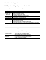
Self diagnosis function of Fnet communication module
7.1.1 Self diagnosis function during running
!
"#"
Items
Contents
Remark
Diagnosis function
(Initial self
diagnosis)
** On-line mode **
1) Memory access error of communication module
2) Common RAM access and Reading/Writing error
3) Interface error of PLC and IBM_PC
4) Frame error during communication
5) Error status in physical layer of other station during communication
6) Error in physical layer of self station during communication
7) Program execution error during communication
Error code is
displayed through
LED when error
occurred
(See Appendix
A1.1/A1.2)
Diagnosis function
(Communication
diagnosis)
** Test mode **
1) Diagnosis of network configuration status in physical layer by test.
– Transmission error of physical layer
– Receive error of physical layer
2) Interface error of CPU in communication module and communication
chip.
Error code is
displayed through
LED when error
occurred
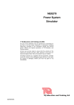
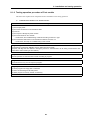
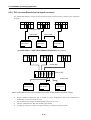
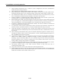
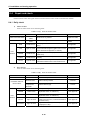
7.1.2 Communication diagnosis by test mode
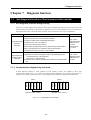
$ % % %&! CPU-A
CPU-B
Input 32 points
Output 32 points
Output 16 points
FUEA(station 1)
Fig. 7.1.2
GM3
POWER
Input 32 points
Output 32 points
Input 16 points
FUEA(station 1)
GM3
POWER
Operation mode : TEST 1
Operation mode : TEST 2
Configuration of test system
7-1
7. Diagnosis function
'
$
"' ()*+()*+,
-
!5-
$ " ()*+ ()*+, .
/
()*+01#121
#
()*+2(
/
()*+,01#1!23"
4"
#
()*+,2(
)()*+()*+,
()*+.
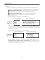
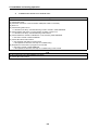
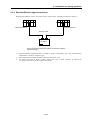
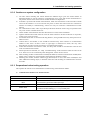
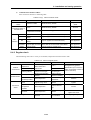
During communication test
One LED rotates
at a time(total
rotation number
256)
RUN = Light on
LAS
TOKEN
TRX
FAULT
Result of communication test
RUN = Flash
LAS = Light on only if receive error occurred
TOKEN = Light on only if transmission error occurred
TRX = Light on if TIME OUT occurred
FAULT = Light on if frame error occurred
%*1 6 137 6 189: 6 # 6
%*1!;<3*:1
" 1 =-
()*+,.
During communication test
One LED rotates
at a time(total
rotation number
256)
Result of communication test
RUN = Light off/Flash
LAS
TOKEN
TRX
FAULT
RUN = Whether error occurred or not
LAS = No meaning
TOKEN = No meaning
TRX = No meaning
FAULT = No meaning
%*1 6 137 6 189: 6 # 6
%*1 !;< 3*: 1 3*: 3*:
$ $ #"
7-2
7. Diagnosis function
7.2
Mnet diagnosis function
7.2.1 Diagnosis function types of Mnet communication module
Items
Diagnosis function
(Self diagnosis +
communication diagnosis)
Contents
Remark
** On-line mode **
1) Memory access error of communication module
2) Common RAM access and Reading/Writing error
3) Interface error of PLC and PC
4) Modem error during communication
5) Error status in physical layer of other station during
communication
6) Error in physical layer of self station during communication
Error code is displayed
7) Program execution error during communication
through LED when
error occurred
** Test mode **
(See appendix A1.7)
1) Diagnosis of network configuration status in physical layer
by test.
– Interface error of common RAM
– Transmission error of physical layer
– Receive error of physical layer
– Loop back test of physical layer
2) Interface error of CPU in communication module and TBC
7.2.2 How to diagnose Mnet communication module
/
!2 !- 1!
1.
Test 1
Test 2
• Interface of common RAM
• Interface of common RAM
• Transmission test of physical layer
• Loop back test
• Receive test of physical layer
• Interface of CPU in communication module and TBC
7-3
7. Diagnosis function
1>
#!
)
(
)
23*: 1
!
23*:$:+3$:? $
23*:%*1 $
!
2%*1$:+3$:? $
!
2%*1$
7-4
#"
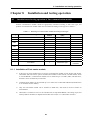
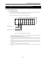
8. Installation and testing operation
?8% )( ()* ()*.
Table 8.1
Mounting of communication module according to CPU type
CPU type
Mountable device type
Max. mounting
number
Mounting location
(slot)
GM1
G3L-MUEA, G3L-FUEA, G3L-FUOA
4
Main base I/O
GM2
G3L-MUEA, G3L-FUEA, G3L-FUOA
4
Main base I/O
G3L-MUEA, G3L-FUEA, G3L-FUOA
4
Main base I/O
G3L-RBEA, G3L-RBOA
1
CPU
GM3
Remark
Remote I/O
G4L-FUEA
2
Main base I/O
G4L-RBEA
1
CPU
GM5
G5L-FUEA
1
I/O
GM6
G6L-FUEA
2
I/O
FAM4.0
G0L-FUEA
1
16 bit extended slot
Mounted in PC
FAM4.0
G0L-MUEA
1
16 bit extended slot
Mounted in PC
-
G0L-SMQA
1
Stand-alone type
Remote output
-
G0L-SMIA
1
Stand-alone type
Remote input
-
G0L-SMHA
1
Stand-alone type
Remote
combined
GM4
Remote I/O
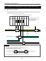
8.1.1 Installation of Fnet master module
-
$
?5+%*?=+%*
?;+%*?<+%*
?5+%*8?@+%* $,/+)((
=?/?/!?/5)(
!-
(
!?/=?/<)(2
"
-
5-
8 ?;+%* ?/; )( =-
?@+%*
<$,/)(
4
"42#5!5?@+%*
-
8-1
8. Installation and testing operation
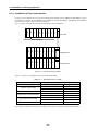
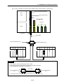
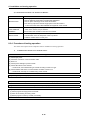
8.1.2 Installation of Fnet slave module
$"
?5+3,?=+3,
?5+3,8 2?@+#/A ?@+#/$ ?@+#/'$ 8<
%B!
"?/
Main base
Fnet
network
Extended base
Extended base
Fig. 8.1.2
How to mount and install
1B!
%#/
Table 8.1.2
Mountable device in FSM
Available module name
Product name
All types of I/O module
D/A conversion module
Temperature conversion module
High speed counter module
A/D conversion module
Not available module name
Product name
Type name
Coordinator module
GM1-CORA
Interface module
All types
Interrupt input module
G!F-INTA
Fnet module
G!l-FUEA/FUOA
Mnet module
G3L-MUEA
PID control module
G!F-PIDA
Analog timer
G!F-AT!A
PC communication module
G!L-CUEA
#
()*
8-2
8. Installation and testing operation
8.1.3 Installation procedure of Fnet module
-
$ ""
!-
1
5-
=-
4 ()*
;-
( / % " ?/ ?/!
?/5,
=
<-
C"
"
$"()*
&-
# 1
B-
(
(8:
(8:!
2%.@Ω/.&;Ω-
D-
$
(8:(8:!
@- 1
$?/$:
- C"
!- (
)(
$#
" )( $
)("
2# 5!5 ?@+%* - #
"
5- 1
)(
8-3
8. Installation and testing operation
8.1.4 Cautions on installation of Fnet module
!-
5=;<-
"
$
$ 3
$ %
* (
1
$
$ &-
,
B-
(
8-4
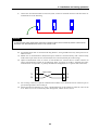
8. Installation and testing operation
D-
(%?)(
"
FG
Remark
If communication status is bad when connection is made as above, this is caused by serious noise from FG.
Therefore, user should eliminate its cause or not connect to FG.
@- $
"
- # 2 - D2#==2--
!- 8 17 37 ( 1 3 $ 1 3 2#=558-
Optical cable
5- %
"
"
=- $ED1
4
$
#"
8-5
8. Installation and testing operation
8.1.5 Preparations during testing operation of Fnet module
1%
Items to be checked
Mounting check of
Base module
Connection status of
Communication cable
Contents
– Does using voltage of power module comply with specifications of power module?
– Is battery of CPU module connected?
– Is mounting of all base modules perfect?
" See product manual according to each PLC type.
– Is connection status of communication cable perfect?
– Is connection type of each cable open loop?
Module mounting
– Is mounting status of communication module which is mounted in basic base perfect?
Switch checking
– Is the status of mode switch On-line(switch value is 0)?
– Is station No. switch correctly set?
– Is master station No. switch correctly set? (for slave module)
– Is output option switch correctly set when communication is cut off? (for slave module)
Items to be checked
Contents
Standard check
– Is PC appropriate IBM-PC compatible?
– Has PC sufficient environment to install FAM4.0/GMWIN?
– Has PC space and empty slot to mount this module?
– Can memory map of PC reserve empty space to use this module?
" See user’s manual of FAM4.0/ GMWIN and Appendix of this manual.
Module mounting and
FAM4.0/GMWIN installation
– Reserve empty space of 32K byte in memory map of PC, select this area for the
memory switch of this module, set port address.
– Mount and fix this module into the slot to be inserted.
Switch recheck
– Are memory switch and port switch correctly set?
– Is mode switch set to On-line(switch value is 0) status?
– Is station number switch correctly set?
8-6
8. Installation and testing operation
8.1.6 Testing operation procedure of Fnet module
1>
)(
Starting
Power on :
(1) Check input power.
(2) Check the connection of communication cable.
(3) Power on.
(4) Check power LED light of power module.
(5) Check LED status of CPU module
" If abnormal, see Troubleshooting of manual according to each PLC type.
(6) Check whether LED status of communication module is normal or not.
" If abnormal, see Chap. 9 Troubleshooting of this manual.
Programming :
Programming is prepared in GMWIN, and it is written into CPU module.
(Properly use flags that are related to emergency action for communication cut-off during communication with
other station and monitoring of other station)
Sequence check :
Checks operation of communication module according to program.
Program correction :
Corrects if there is any error of sequence program.
Program preservation :
(1) Stores program into floppy disk or hard disk.
(2) Prints circuit drawing and list with printer.
(3) Writes program to memory module, if necessary.
End
8-7
8. Installation and testing operation
Starting
Power :
(1) Check input power.
(2) Check the connection of communication cable(when cable is connected).
(3) Power on.
(4) Check booting status of PC.
" If abnormal, see Chap. 9 Troubleshooting of user’s manual in FAM4.0/GMWIN.
(5) Check whether LED status of communication module is normal or not.
" If abnormal, see Chap. 9 Troubleshooting of this manual.
(6) Check whether this module is initialized or not by executing FAM4.0/GMWIN.
" See user’s manual of FAM 4.0/GMWIN.
(7) Check LED status of this module.
" See ‘Appendix LED status’ of this manual.
If the operation is abnormal, see chap. 9 Troubleshooting.
(8) Preparation and execution of program to be executed.
" See user’s manual of FAM4.0/GMWIN.
If the operation is abnormal, see chap. 9 Troubleshooting of this manual.
End
(1) Stop all execution of FAM4.0/GMWIN, and finish.
(2) Check LED of this module.
8-8
8. Installation and testing operation
8.2
Installation and testing operation of Fnet option unit
8.2.1 Active coupler of Fnet
"
?@+%)2)- ?@+%,2,- ?@+%(2/
-
%B!"
Optical module 1
Optical module 2
Fig. 8.2.1
Example of active coupler mounting
2- )
""
2!- 1
25- 2=- "
"
"
)
2;- (
2<- /
2?@+%- 8-9
8. Installation and testing operation
8.2.2 E/O converter(Electric/optical signal converter)
1
2?@+%8-"%
.
Twisted
pair cable
Optical
cable
Optical
cable
?8+%8
?8+%8
?8+%8
[When
optical
cable
is used!"#
to connect
modules
of Gmany stations]
$Fnet
F
%
between
%&'
()
Optical
cable
Active
*+,coupler
-.
Optical
cable
?8+%8
?8+%8
?8+%8
[When
cable
is used to01
connect between
Fnet %
modules!"#
of many
stations
using %&'
active coupler]
optical
F*+,
-./
$
()G
!5=-
) ""
1
(
(
1 3
8-10
8. Installation and testing operation
8.2.3 Repeater(Electric signal restructure)
32?@+%3-
%$.
Terminal resistance
78 9:
Terminal
resistance
78 9:
Twist pair
cable
?8+%3
[When
signal23/
between4516
Fnet modules
is restruct(to make the
F% the!"
()G
signal level ‘High’)
!5-
) ""
1
1 1
8-11
8. Installation and testing operation
8.3
Installation and testing operation of Mnet communication module
8.3.1 Mounting and installation
$ / ?5+/* ?@+/* )(
(
/=2
%- ?/ ?/! ?/5)(
Fig. 8.3.1(A)
Power
Example of G3L-MUEA module mounting
Communication module 1 and 2
are the same network.
Communication module 3 and 4
are different network
CPU
! 5 =
Drop cable
TAP
T1
T2
T1
Trunk cable
TAP
Terminal resistance(75Ω)
T1
T2
TAP
T1
T2
Remark
1. Max. distance of trunk cable between TAPs is 700m.
2. Drop cable between TAP and Mnet communication module is max. 50m.
3. Operate while paying attention to TAP direction.
Trunk cable
Terminal resistance
75Ω
T1
T2
T1
T2
Terminal resistance
75Ω
4. Connect the screw for shield connection at the back of TAP with pannel FG.
8-12
T2
TAP
8. Installation and testing operation
Fig. 8.3.1(B)
Example of mounting of G0L-MUEA module in PC(mounted in 16 bit AT bus)
Mnet communication module
HDD
FDD
16 bit extension slot
Computer
8 bit slot
Power
F_connector
Drop cable
Terminal resistance(75Ω)
T1
T2
Terminal resistance(75Ω)
2&;Ω-
Tap
Power
CPU
()
Power CPU
Drop cable
Remark
1. Max. distance of trunk cable between TAPs is 700m.
2. Drop cable between TAP and Mnet communication module is max. 50m.
3. Operate while paying attention to TAP direction.
Trunk cable
Terminal resistance
75Ω
T1
T2
T1
T2
Terminal resistance
75Ω
4. Connect the screw for shield connection at the back of TAP with pannel FG.
8-13
8. Installation and testing operation
!5=;<-
&BD-
@-
-
!5=;-
$ ""
1
)(
4 (
()*
$"?/ ! 5
/
%
,
/=
C"
"
$"()*
$ 1)
$ 1) $
1
1) 1)
2$
-
$ )(?/$:
(
)(
<
" )( $
)("
# "
1
)(
1 1) &@@ 1) ;@
*1)%?1)%?
#
" /( "
8-14
8. Installation and testing operation
8.3.2 Cautions on system configuration
-
" $
#"
!- $
8+$
5- %
* =- (
;- 1
$
<- $
"
&- ( 5@ $ B- 1
1) 1)
D- $E(D1
4
$
#"
@- /
2?@+/*-%
2?@+
%*-)(
%/=@
"
- /
2; - 2 C-
8.3.3 Preparations before testing operation
1
Items to be checked
Installation and check of standard S/W
Connection status of communication
cable
Module mounting
Switch check
Contents
– Are installation and operation of GMWIN perfect?
– Are connection of communication cable and using status of TAP perfect?
– Is connection type of each cable open loop?
– Is communication module correctly installed in main base?
– Is mode switch On-line(switch value : 0)?
– Is station number switch(
) correctly set?
8-15
8. Installation and testing operation
Items to be checked
Standard check
Contents
– Is PC appropriate IBM-PC compatible?
– Has PC sufficient environment to install FAM4.0/GMWIN?
– Has PC space and empty slot to mount this module?
– Can memory map of PC reserve empty space to use this module?
" See user’s manual of FAM4.0/GMWIN and Appendix of this manual.
Module mounting and – Reserve empty space of 64K byte in memory map of PC, select this area for the memory
switch of this module, set port address.
FAM4.0/GMWIN
installation
– Mount and fix this module into the slot to be inserted.
Switch recheck
– Are memory switch and port switch correctly set?
– Is mode switch set to On-line(switch value is 0) status?
– Is station number switch correctly set?
8.3.4 Procedure of testing operation
1>
)(
Starting
Power on :
(1) Check input power.
(2) Check the connection of communication cable.
(3) Power on.
(4) Check power LED light of power module.
(5) Check LED status of CPU module.
" If abnormal, see troubleshooting of manual according to each PLC type.
(6) Check whether LED status of communication module is normal or not.
" If abnormal, see Chap. 9 Troubleshooting of this manual.
Programming : Programming is prepared in GMWIN, and it is written into CPU module.
Sequence check : Checks operation of communication module according to program.
Program correction : Corrects if there is any error of sequence program.
Program preservation :
(1) Stores program into floppy disk or hard disk.
(2) Prints circuit drawing and list by printer.
(3) Writes program to memory module, if necessary.
End
8-16
8. Installation and testing operation
2) Communication module to be mounted in PC
Starting
Power on :
1) Check input power.
2) Check the connection of communication cable.
3) Power on.
4) Check booting status of PC.
" If booting is not performed, check port address and memory address which are set in communication module
and set memory so as not to be duplicated with other devices used in PC.
" If abnormal, see Chap. 9 Troubleshooting of user’s manual in FAM4.0/GMWIN.
5) Check whether LED status of communication module is normal or not.
" If abnormal, see Chap. 9 Troubleshooting of this manual.
6) Check whether this module is initialized or not by executing FAM4.0/GMWIN.
" See user’s manual of FAM 4.0/GMWIN.
7) Check LED status of this module.
" See ‘Appendix LED status’ of this manual.
If the operation is abnormal, see Chap. 9 Troubleshooting.
8) Preparation and execution of program to be executed.
" See user’s manual of FAM4.0/GMWIN.
If the operation of communication is abnormal, see user’s manual of FAM4.0/GMWIN.
End
1) Stop all execution of FAM4.0/GMWIN, and finish.
2) Check LED of this module.
8-17
8. Installation and testing operation
8.4
Repair and check
)
8.4.1 Daily check
$
.
Table 8.4.1(A)
Items to be checked
Contents
Cable connection status
Release of
cable
Module connection status
Release of
screw
LED
indication
Items of routine check
Criteria of decision
Action to take
Shall not be any release.
Tighten the cable.
Shall not be any release.
Tighten screw of
module.
Flash (Lights-out means interface cut-off with
CPU).
RUN
Flicker check
See Appendix.
LAS
Light on Check
TOKEN
Flicker check
Light off means abnormal (Duplicated station or
cable error).
See Appendix.
TX/RX
Flicker check
Light off means abnormal (Hardware error of
module).
See Appendix.
FAULT
Light off check
Regular flash means system error, and
intermittence flash means communication error.
See Appendix.
LED of only one module among entire module of
network should be lighted (Lights of two or more See Appendix.
mean abnormal configuration of network).
$
.
Table 8.4.1(B)
Items of routine check
Items to be checked
Contents
Cable connection status
Release of cable
Shall not be any release.
Tighten the cable.
Release of
terminal screw
Shall not be any release.
Tighten screw of
terminal.
Gap between
compression
terminals
Shall be relevant gap.
Connection status of
terminal block
LED
indication
RUN
Light on check
TOKEN
Criteria of decision
Action to take
Correct.
Check power if light off.
See Appendix.
Flicker check
Light off means abnormal operation
(Duplicated station or cable error).
See Appendix.
TX/RX
Flicker check
Light off means abnormal operation
(Duplicated station or cable error).
See Appendix.
FAULT
Light off check
Intermittent flash means communication error
(Cable connection error, or terminal resistance
connection error).
See Appendix.
SYS FAULT
Light off check
Regular flash means system error (Error code
is displayed in LED).
See Appendix.
8-18
8. Installation and testing operation
$
.
Table 8.4.1(C)
Items to be checked
Cable connection
status
Connection status of
terminal block
RUN
LED
indication
Items of routine check
Contents
Criteria of decision
Release of cable
Action to take
Tighten the
cable.
Shall not be any release.
Release of terminal
Shall not be any release.
screw
Tighten screw of
terminal.
Gap between
Shall be relevant gap.
compression terminals
Light on (Lights-out means abnormal).
See Appendix.
TX
Light on check in RUN
Light on (Lights-out means abnormal).
status
See Appendix.
RX
Light on check in RUN
Light on (Lights-out means abnormal).
status
See Appendix.
IN-RING
FAULT
Light on check
Correct.
Light on/light off check
Light on (Light off means abnormal) Lights
when cable is connected with other station.
See Appendix.
Light off check
Light off (Light on or flash error).
See Appendix.
8.4.2 Regular check
("
Table 8.4.2
Items to be checked
Ambient
temperature
Ambient
environment
Module status
Connection
status
Items of regular check
How to check
Criteria of decision
Action to take
Ambient humidity
Check using
thermometer and
hydrometer.
Ambient pollution
Check corrosive gas.
Shall not be any
corrosive gas.
Release, shaking
Shake communication
module.
Shall not be any
release or shaking.
Attachment of dust
and foreign matter
Visual inspection.
Shall not be any
attachment.
Remove
Release of terminal
screw
Tighten using driver.
Shall not be any
release.
Tighten.
Gap between
compression
terminals
Visual inspection.
Shall be relevant
gap.
Correct.
Release of
connector
Visual inspection.
Shall not be any
release.
Fix the connector
Tighten the screw.
Power voltage check
0~55
5~95%RH
Check voltage between AC 85~132V
terminal.
AC 170~264V
8-19
Arrangement by general
specification (If it is used in a
class, environment of class is
used as standard).
Tighten the screw.
Change supplied power.

![[13] Chap.11 Trouble Shooting](http://vs1.manualzilla.com/store/data/005753222_1-b84b48489eb920e39ff2c53b244a8bf5-150x150.png)