1
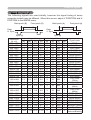
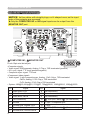
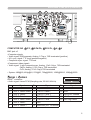
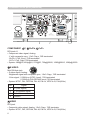
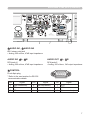
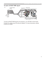
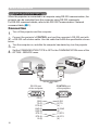
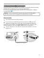
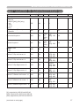
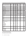
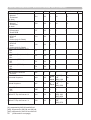
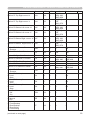
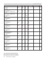
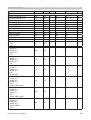
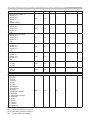
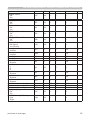
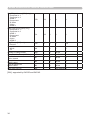
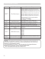
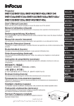
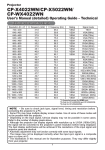
Projector
IN5132/IN5132c/IN5142/IN5142c/
IN5134/IN5134c/IN5144/IN5144c/
IN5135/IN5135c/IN5145/IN5145c
User's Manual (detailed)
Operating Guide – Technical
Example of computer signal
Resolution (H x V) H. frequency (kHz) V. frequency (Hz)
Rating
Signal mode
37.9
31.5
37.9
37.5
43.3
35.2
37.9
48.1
46.9
53.7
49.7
48.4
56.5
60.0
68.7
67.5
47.7
49.7
60.0
64.0
80.0
55.9
VESA
VESA
VESA
VESA
VESA
VESA
VESA
VESA
VESA
VESA
TEXT
VGA (60Hz)
VGA (72Hz)
VGA (75Hz)
VGA (85Hz)
SVGA (56Hz)
SVGA (60Hz)
SVGA (72Hz)
SVGA (75Hz)
SVGA (85Hz)
Mac 16” mode
XGA (60Hz)
XGA (70Hz)
XGA (75Hz)
XGA (85Hz)
1152 x 864 (75Hz)
W-XGA (60Hz)
1280 x 800 (60Hz)
1280 x 960 (60Hz)
SXGA (60Hz)
SXGA (75Hz)
WXGA+ (60Hz)
720 x 400
640 x 480
640 x 480
640 x 480
640 x 480
800 x 600
800 x 600
800 x 600
800 x 600
800 x 600
832 x 624
1024 x 768
1024 x 768
1024 x 768
1024 x 768
1152 x 864
1280 x 768
1280 x 800
1280 x 960
1280 x 1024
1280 x 1024
1440 x 900
85.0
59.9
72.8
75.0
85.0
56.3
60.3
72.2
75.0
85.1
74.5
60.0
70.1
75.0
85.0
75.0
60.0
60.0
60.0
60.0
75.0
59.9
VESA
VESA
VESA
VESA
VESA
VESA
VESA
VESA
VESA
VESA
VESA
(continued on next page)
009-1418-00
1
Example of computer signal
Resolution (H x V)
H. frequency (kHz)
V. frequency (Hz)
Rating
Signal mode
1280 x 1024
1400 x 1050
1680 x 1050
1600 x 1200
91.1
65.2
65.3
75.0
85.0
60.0
60.0
60.0
VESA
VESA
VESA
VESA
*4 1920 x 1200
74.0
60.0
VESA
SXGA (85Hz)
SXGA+ (60Hz)
WSXGA+ (60Hz)
UXGA (60Hz)
W-UXGA (60Hz)
Reduced Blanking
*1
*2
*3
*1
*1) Supported except for HDMI input.
*2) Only for IN5132 and IN5142.
*3) Only for IN5134, IN5144, IN5135 and IN5145.
*4) Only for IN5135 and IN5145, excluding the HDMITM input.
TM
NOTE • Verify the connector type, signal level, timing and resolution before
connecting this projector to a computer.
• Some computers may have multiple display screen modes. Some of these
modes may not be compatible with this projector.
• Depending on the input signal, full-size display may not be possible in some
cases. Refer to the number of display pixels above.
• Although the projector can display signals with resolutions up to UXGA
(1600x1200) or up WUXGA (1920x1200) for IN5135 and IN5145, the signal will
be scaled to the projector’s native resolution before being displayed. The best
display performance occurs when the input signal and projector resolutions are
identical.
• Automatic adjustment may not function correctly for all input signals.
• If the input sync signal is a composite sync or a sync on G signal, the image
may not display correctly.
2
Initial set signals
Initial set signals
The following signals are used initially, however the signal timing of some
computer models may be different. When this occurs, adjust V POSITION and H
POSITION in the IMAGE menu.
Back porch (B)
Front porch (D)
Active video (C)
Data
H. Sync.
Back porch (b)
Resolution
(H x V)
720 x 400
640 x 480
640 x 480
640 x 480
640 x 480
800 x 600
800 x 600
800 x 600
800 x 600
800 x 600
832 x 624
1024 x 768
1024 x 768
1024 x 768
1024 x 768
Active video (c)
Data
V. Sync.
Sync (A)
Sync (a)
Horizontal signal timing (μs) Vertical signal timing (lines)
(A)
(B)
(C)
(D)
(a)
(b)
(c)
(d)
2.0
3.0 20.3 1.0
3
42
400
1
3.8
1.9 25.4 0.6
2
33
480
10
1.3
4.1 20.3 0.8
3
28
480
9
2.0
3.8 20.3 0.5
3
16
480
1
1.6
2.2 17.8 1.6
3
25
480
1
2.0
3.6 22.2 0.7
2
22
600
1
3.2
2.2 20.0 1.0
4
23
600
1
2.4
1.3 16.0 1.1
6
23
600
37
1.6
3.2 16.2 0.3
3
21
600
1
1.1
2.7 14.2 0.6
3
27
600
1
1.1
3.9 14.5 0.6
3
39
624
1
2.1
2.5 15.8 0.4
6
29
768
3
1.8
1.9 13.7 0.3
6
29
768
3
1.2
2.2 13.0 0.2
3
28
768
1
1.0
2.2 10.8 0.5
3
36
768
1
1152 x 864
1.2
2.4
10.7
0.6
3
32
864
1
1280 x 768
1.7
2.5
16.0
0.8
3
23
768
1
1280 x 800
1.6
2.4
15.3
0.8
3
24
800
1
1280 x 960
1.0
2.9
11.9
0.9
3
36
960
1
1280 x 1024
1280 x 1024
1280 x 1024
1400 x 1050
1440 x 900
1680 x 1050
1600 x 1200
1.0
1.1
1.0
1.2
1.4
1.2
1.2
2.3
1.8
1.4
2.0
2.2
1.9
1.9
11.9
9.5
8.1
11.4
13.5
11.5
9.9
0.4
0.1
0.4
0.7
0.8
0.7
0.4
3
3
3
3
6
6
3
38
38
44
33
25
30
46
1024
1024
1024
1050
900
1050
1200
1
1
1
1
3
3
1
6
26
1200
3
1920 x 1200
Front porch (d)
0.208 0.519 12.47 0.312
Signal mode
TEXT
VGA (60Hz)
VGA (72Hz)
VGA (75Hz)
VGA (85Hz)
SVGA (56Hz)
SVGA (60Hz)
SVGA (72Hz)
SVGA (75Hz)
SVGA (85Hz)
Mac 16" mode
XGA (60Hz)
XGA (70Hz)
XGA (75Hz)
XGA (85Hz)
1152 x 864
(75Hz)
W-XGA (60Hz)
1280 x 800
(60Hz)
1280 x 960
(60Hz)
SXGA (60Hz)
SXGA (75Hz)
SXGA (85Hz)
SXGA+ (60Hz)
WXGA+ (60Hz)
WSXGA+ (60Hz)
UXGA (60Hz)
W-UXGA (60Hz)
Reduced Blanking
3
Connection to the ports
Connection to the ports
NOTICE ►Use cables with straight plugs, not L-shaped ones, as the input
ports of the projector are recessed.
►Only the COMPUTER IN1 or IN2 signal inputs can be output from the
MONITOR OUT port.
A
B
A COMPUTER IN1, B MONITOR OUT
⑪⑫⑬⑭⑮
⑥⑦⑧⑨⑩
①②③④⑤
D-sub 15pin mini shrink jack
<Computer signal>
• Video signal: RGB separate, Analog, 0.7Vp-p, 75Ω terminated (positive)
• H/V. sync. signal: TTL level (positive/negative)
• Composite sync. signal: TTL level
<Component video signal>
• Video signal: Y with composite sync, Analog, 1.0±0.1Vp-p, 75Ω terminated
Cb/Pb, Analog, 0.7±0.1Vp-p, 75Ω terminated
Cr/Pr, Analog, 0.7±0.1Vp-p 75Ω terminated
• System: 480i@60, 480p@60, 576i@50, 720p@50/60, 1080i@50/60, 1080p@50/60
Pin
4
Signal
Pin
Signal
1
Video Red, Cr/Pr
9
(No connection)
2
Video Green, Y
10
Ground
3
Video Blue, Cb/Pb
11
(No connection)
4
(No connection)
12
5
Ground
13
A : SDA (DDC data) B : (No connection)
H. sync / Composite sync.
6
Ground Red, Ground Cr/Pr
14
V. sync.
7
Ground Green, Ground Y
15
A : SCL (DDC clock) B : (No connection)
8
Ground Blue, Ground Cb/Pb
⑤④
⑩
⑮⑭
Connection to the ports (continued)
H
I
C
D
F
E
G
COMPUTER IN2 C G/Y, D B/Cb/Pb, E R/Cr/Pr, F H, G V
BNC jack x5
<Computer signal>
• Video signal: RGB separate, Analog, 0.7Vp-p, 75Ω terminated (positive)
• H/V. sync. signal: TTL level (positive/negative)
• Composite sync. signal: TTL level
<Component video signal>
• Video signal: Y with composite sync, Analog, 1.0±0.1Vp-p, 75Ω terminated
Cb/Pb, Analog, 0.7±0.1Vp-p, 75Ω terminated
Cr/Pr, Analog, 0.7±0.1Vp-p 75Ω terminated
• System: 480i@60, 480p@60, 576i@50, 720p@50/60, 1080i@50/60, 1080p@50/60
H HDMI 1, I HDMI 2
HDMITM connector
• Audio signal: Linear PCM (Sampling rate; 32/44.1/48 kHz)
Pin
Signal
Pin
Signal
②④⑥⑧⑩⑫⑭⑯⑱
⑲⑰⑮⑬⑪
①③⑤⑦⑨⑪⑬⑮⑰⑲
⑱⑯⑭⑫
Pin
Signal
1
T.M.D.S. Data2 +
8
T.M.D.S. Data0 Shield
15 SCL
2
T.M.D.S. Data2 Shield
9
T.M.D.S. Data0 -
16 SDA
3
T.M.D.S. Data2 -
10 T.M.D.S. Clock +
17 DDC/CEC Ground
4
T.M.D.S. Data1 +
11 T.M.D.S. Clock Shield
18 +5V Power
19 Hot Plug Detect
5
T.M.D.S. Data1 Shield
12 T.M.D.S. Clock -
6
T.M.D.S. Data1 -
13 CEC
7
T.M.D.S. Data0 +
14 Reserved (N.C. on device)
5
Connection to the ports (continued)
M
N
L
K
J
COMPONENT J Y, K Cb/Pb, L Cr/Pr
RCA jack x3
①
③
• Component video signal, Analog:
-Y with composite sync, 1.0±0.1Vp-p, 75Ω terminated
-Cb/Pb, 0.7±0.1Vp-p, 75Ω terminated
-Cr/Pr, 0.7±0.1Vp-p 75Ω terminated
• System: 480i@60, 480p@60, 576i@50, 720p@50/60, 1080i@50/60, 1080p@50/60
②
④
2 4
④
②
M S-VIDEO
1 3
③
①
Mini DIN 4pin jack
• S-video signal, Analog:
-Brightness signal with composite sync, 1.0±0.1Vp-p, 75Ω terminated
-Color signal, 0.286Vp-p (NTSC, burst), 75Ω terminated
0.300Vp-p (PAL/SECAM, burst) 75Ω terminated
• System: NTSC, PAL, SECAM, PAL-M, PAL-N, NTSC4.43, PAL(60Hz)
Pin
Signal
1
C (color signal)
2
Y (brightness signal)
3
Ground
4
Ground
N VIDEO
RCA jack
• Composite video signal, Analog, 1.0±0.1Vp-p, 75Ω terminator
• System: NTSC, PAL, SECAM, PAL-M, PAL-N, NTSC4.43, PAL(60Hz)
6
Connection to the ports (continued)
U
S
Q
T
R
O
P
O AUDIO IN1, P AUDIO IN2
Ø3.5 stereo mini jack
• Analog, 500 mVrms, 47kΩ input impedance
AUDIO IN3 Q L, R R
AUDIO OUT S L, T R
RCA jack x2
RCA jack x2
• Analog, 500 mVrms, 47kΩ input impedance
• Analog, 500 mVrms, 1kΩ output impedance
U CONTROL
D-sub 9pin plug
① ② ③ ④ ⑤
⑨ ⑧ ⑦ ⑥
⑥ ⑦ ⑧ ⑨
⑤ ④ ③ ② ①
* Refer to the next section for RS-232
communication details.
Pin
Signal
Pin
Signal
Pin
Signal
1
(No connection)
4
(No connection)
7
RTS
2
RD
5
Ground
8
CTS
3
TD
6
(No connection)
9
(No connection)
7
Connection to the ports (continued)
X
W
V
Y
Z
V LAN
RJ-45 jack
Pin
1
Signal
TX+
Pin
4
Signal
-
8
-
TX-
5
-
RX+
6
RX-
W USB TYPE A
Pin
Signal
④ ③② ①
④ ③② ①
X USB TYPE B
USB B type jack
Pin
Signal
① ②③ ④
+5V
1
+5V
2
- Data
2
- Data
3
+ Data
3
+ Data
4
Ground
4
Ground
Ø3.5 stereo mini jack
④③
②①
①②
③④
① ②③ ④
1
REMOTE CONTROL Y IN, Z OUT
8
Signal
7
2
USB A type jack x2
Pin
-
3
⑧ ⑥ ④ ②
⑦ ⑤ ③ ①
② ④ ⑥ ⑧
① ③ ⑤ ⑦
* Refer to the Network Guide for more details.
Connection to the ports (continued)
To input a SCART RGB signal:
ex.
SCART cable
(plug)
Audio R
RCA plugs
Audio L
Video
R
SCART
connector
(jack)
B
G
To input a SCART RGB signal to the projector, use a SCART to RCA cable.
Connect the cables as per the above example. For more information, please
consult your dealer.
9
RS-232 Communication
RS-232 Communication
When the projector is connected to a computer using RS-232 communication, the
projector can be controlled from the computer using RS-232 commands.
For RS-232 command details, refer to the RS-232 Communication / Network
command table (&17).
Connection
1. Turn off the projector and the computer.
the projector's CONTROL port and the computer's RS-232 port with
2. Connect
a RS-232 null modem cable. Use the cable that fulfills the specification shown
below.
Turn the computer on, and after the computer has started up, turn the projector
on.
Set the COMMUNICATION TYPE to OFF in the COMMUNICATION menu of the
OPTION - SERVICE menu.
3.
4.
RS-232
CONTROL
RS-232 null modem
cable
CONTROL port
of the projector
RS-232 port
of the computer
1
2
6
3
7
4
8
6
5
9
1
7
2
8
3
9
4
5
CD (1)
RD(2)
TD (3)
DTR (4)
GND (5)
DSR (6)
RTS (7)
DTS (8)
RI (9)
10
① ② ③ ④ ⑤
⑨ ⑧ ⑦ ⑥
⑥ ⑦ ⑧ ⑨
⑤ ④ ③ ② ①
(1) -
(2) RD
(3) TD
(4) -
(5) GND
(6) -
(7) RTS
(8) CTS
(9) -
RS-232 Communication (continued)
RS-232 Commands
IMPORTANT: When formatting commands sent from a control system or computer,
enclose commands in parentheses “(“ and “)”.
Communication Configuration
Visit our website for additional RS-232 settings and information.
To control this projector via RS-232, connect a null modem cable and set the control
system serial port settings to match the following communication configuration:
RS-232 Port Settings
Setting
Value
Bits per second
19,200
Data bits
8
Parity
None
Stop bits
1
Flow control
None
Emulation
VT100
Command Format
All commands consist of 3 alpha characters followed by a request, all enclosed in
parentheses. The request can be a read request (indicated by a "?") or a write request
(indicated by 1 to 4 ASCII digits).
A read request example:
(AAA?) where
(starts the command
AAA denotes the command
? denotes the read request
) ends the command
A read command returns the range and the current setting, for example:
Read Command Examples
Function
Command
Brightness
(BRT?)
Volume
(VOL?)
Lamp Hours
(LMP?)
Response
(96-160, 128)
(0-32, 0)
(0-32766, 42)
11
RS-232 Communication (continued)
A write request example:
(AAA####) where
(starts the command
AAA denotes the command
#### denotes the value to be written
(leading zeros not necessary)
) ends the command
Some commands have ranges, while others are absolute. If a number greater
than the maximum range is received, it is automatically set to the maximum
number for that function. If a command is received that is not understood, a "?" is
returned. With absolute settings, "0" is off, 1-9999 is on. The one exception is the
Power command, where 0 is off and 1 is on.
To change the value, add "+" before the value to be written to increase the value
or "-" before the value to decrease the value.
To assure the projector can process a command, wait 3 seconds before entering
the next command.
Write Command Examples
Function
Brightness
Command
(BRT140)
Power
Power
(PWR0)
(PWR1)
Response
Sets the brightness to
140
Turns power off
Turns power on
Error Conditions
Not all commands are supported for all projectors. If an unsupported command
is issued, the command will be ignored. If a command is received that is not
understood, a ‘?’ character will be returned indicating the command was not
understood.
Limitations
The projector cannot respond to commands coming in at a high-rate. Therefore, a
delay must occur between commands to ensure that the command gets properly
executed. To assure the projector can process a command, wait 3 seconds before
entering the next command.
The Step column refers to increasing or decreasing the menu bar position since
the On-screen Display is not an exact match of values. For example, Step 2
changes the data by 2 through the CLI (Command Line Interface). The menu bar
is up (or down) by 1.
12
Command Control via the Network
Command Control via the Network
When the projector is connected to the network, the projector can be controlled
with RS-232 commands from the computer's web browser.
For RS-232 command details, refer to the RS-232 Communication / Network
command table (&17).
NOTE • If data is transferred via wireless and wired LAN at the same
time, the projector may not be able to process the data correctly.
Connection
Turn off the projector and the computer.
1.
If you are using a wired LAN, connect the projector's LAN port to the
2. computer's LAN port with a LAN cable. Use the cable that fulfills the
specification shown below. If you are using a wireless LAN, insert the USB
wireless adapter into one of the USB TYPE A ports of the projector.
Turn the computer on, and after the computer has started up, turn the
projector on.
3.
USB wireless adapter
LAN
LAN cable (CAT-5 or greater)
13
Command Control via the Network
Communication Port
Port no. 23 (TCP #23) is assigned for command control.
Command Format
Use the same command format as is used for RS-232 commands (&11).
Automatic Connection Break
The TCP connection will automatically disconnect after 30 seconds of inactivity.
14
Network Bridge Communication
Network Bridge Communication
This projector is equipped with the NETWORK BRIDGE function.
When the projector is connected to a computer using wired or wireless LAN
communicaton, an external device connected to this projector by RS-232
communication can be controlled from the computer as a network terminal.
For details, review the 6. Network Bridge function in the Network Guide.
NOTE • The projector may not be able to process the data correctly when
data is simultaneously transferred via both wireless and wired LAN.
Connection
If you are using a wired LAN, connect the computer's LAN port and the
1. projector's LAN port with a LAN cable. Use a cable per the specifications
shown below. If you are using a wireless LAN, insert a USB wireless adapter
into the projector's LAN port.
Connect an RS-232 cable between the projector's CONTROL port and the
RS-232 port of the device.
Turn the computer on, and after the computer has started up, turn the
projector on.
Set the COMMUNICATION TYPE to NETWORK BRIDGE in the
COMMUNICATION menu of the OPTION - SERVICE menu.
2.
3.
4.
USB wireless adapter
LAN
LAN cable
(CAT-5 or greater)
RS-232 null
modem cable
RS-232
15
Network Bridge Communication
Communication settings
To use communication settings, use the COMMUNICATION menu in the OPTION
- SERVICE menu
Item
BAUD RATE
Condition
4800bps / 9600bps / 19200bps / 38400bps
Data bits
8 (fixed)
PARITY
NONE/ODD/EVEN
Start bit
1 (fixed)
Stop bit
1 (fixed)
Transmission method
HALF-DUPLEX/FULL-DUPLEX
NOTE • When connecting the projector to your devices, please read the
manual for each device, and connect them correctly with suitable cables.
• Turn off the power and unplug both the projector and other devices before
connecting them.
• For Transmission method details, refer to 6.4 Transmission methods in the
Network Guide.
16
RS-232 Communication / Network command table
RS-232 Communication / Network command table
Function
Aspect Ratio
0: Normal
1: Native ([WX], [WU] only)
2: 4:3
3: 16:9
6: 16:10
9:14:9
Auto Keystone (Execute)
1: Execute
Horizontal Keystone
Command RW
Min
EASY MENU
Max
Default
ARZ
RW
0
9
0
AVK
W
0
1
n/a
[X],
[WX]:
38
[WU]:
88
[X],
[WX]:
38
[WU]:
48
[X], [WX]:
218
[WU]: 168
128
1
[X], [WX]:
218
[WU]: 208
128
1
1
0
DKH
RW
Vertical Keystone
DKV
RW
Perfect Fit On
0: Off
1: On
CNE
RW
0
Perfect Fit Top Left corner -H
CN1
RW
0
Perfect Fit Top Left corner -V
CN2
RW
0
Perfect Fit Top Right corner -H
CN3
RW
0
Perfect Fit Top Right corner -V
CN4
RW
0
Perfect Fit Bottom Left corner - H CN5
RW
0
Perfect Fit Bottom Left corner - V
CN6
RW
0
Perfect Fit Bottom Right corner - H CN7
RW
0
[X]: 511
[WX]: 639
[WU]: 959
[X], [WX]:
550
[WU]: 570
[X]: 511
[WX]: 639
[WU]: 959
[X], [WX]:
550
[WU]: 570
[X]: 511
[WX]: 639
[WU]: 959
[X], [WX]:
550
[WU]: 570
[X]: 511
[WX]: 639
[WU]: 959
Step
0
1
0
1
0
1
0
1
0
1
0
1
0
1
[X]: supported by IN5132 and IN5142.
[WX]: supported by IN5134 and IN5144.
[WU]: supported by IN5135 and IN5145.
(continued on next page)
17
RS-232C Communication / Network command table (continued)
Function
Command
Perfect Fit Bottom Right corner - V CN8
Perfect Fit All Corners reset
1: Execute
Perfect Fit Left Side Distortion
([X], [WX] only)
Perfect Fit Right Side Distortion
([X], [WX] only)
Perfect Fit Distortion V Position
([X], [WX] only)
Perfect Fit Top Side Distortion
([X], [WX] only)
Perfect Fit Bottom Side Distortion
([X], [WX] only)
Perfect Fit Distortion H Position
([X], [WX] only)
Perfect Fit All Sides Reset
1: Execute
Perfect Fit Memory 1
0: Load
1: Save
Perfect Fit Memory 2
0: Load
1: Save
Perfect Fit Memory 3
0: Load
1: Save
Picture Mode
1: Custom (read only)
5: Normal
7: Cinema
10: Daytime
11: Whiteboard
12: Blackboard
13: Greenboard
15: Dynamic
16: Dicom Sim.
Eco Mode
0: Normal
1: Eco
Installation
0: Front/Desktop
1: Rear/Desktop
2: Rear/Ceiling
3: Front/Ceiling
(continued on next page)
Min
Max
[X], [WX]:
550
[WU]: 570
Default
Step
0
1
RW
0
CNR
W
0
1
n/a
SC1
RW
98
158
128
1
SC2
RW
98
158
128
1
SC3
RW
0
[X]: 768
[WX]: 800
[X]: 384
[WX]: 400
1
SC4
RW
98
158
128
1
SC5
RW
98
158
128
1
[X]: 512
[WX]: 640
1
SC6
RW
0
[X]: 1024
[WX]: 1280
SCR
W
0
1
n/a
CS1
W
0
1
n/a
CS2
W
0
1
n/a
CS3
W
0
1
n/a
PST
RW
1
16
5
LPE
RW
0
1
0
IST
RW
0
3
0
[X]: supported by IN5132 and IN5142.
[WX]: supported by IN5134 and IN5144.
[WU]: supported by IN5135 and IN5145.
18
RW
RS-232C Communication / Network command table (continued)
Function
Easy Menu Reset
1: Execute
Filter Time
Filter Time Reset
1: Reset
Language
0: English
1: French
2: German
3: Italian
5: Korean
6: Norwegian
7: Portuguese
8: Russian
9: Simplified Chinese
10: Spanish
11: Traditional Chinese
12: Swedish
13: Dutch
14: Polish
15: Turkish
17: Finnish
18: Japanese
Brightness
Contrast
Gamma
32: 1 Default
16: 1 Custom
33: 2 Default
17: 2 Custom
34: 3 Default
18: 3 Custom
35: 4 Default
19: 4 Custom
36: 5 Default
20: 5 Custom
37: 6 Default
21: 6 Custom
38: 7 Default
22: 7 Custom
Gamma Pattern
0: Off
1: 9 steps gray scale
2: 15 steps gray scale
3: Ramp
Gamma Point 1
Gamma Point 2
Gamma Point 3
Gamma Point 4
(continued on next page)
Command
RW
Min
Max
Default
MRT
W
0
1
n/a
FLT
R
0
999999
n/a
FRT
W
0
1
n/a
LAN
RW
0
18
0
ADVANCED MENU: PICTURE
BRT
RW
96
160
CON
RW
96
160
128
128
GTB
RW
16
38
32
GTP
RW
0
3
0
GP1
GP2
GP3
GP4
RW
RW
RW
RW
112
112
112
112
144
144
144
144
128
128
128
128
Step
1
1
1
1
1
1
19
RS-232C Communication / Network command table (continued)
Function
Gamma Point 5
Gamma Point 6
Gamma Point 7
Gamma Point 8
Color Temperature
0: 1 High
1: 1 Custom
2: 2 Mid
3: 2 Custom
4: 3 Low
5: 3 Custom
6: 4 Hi-Bright-1
7: 4 Custom
8: 5 Hi-Bright-2
9: 5 Custom
10: 6 Hi-Bright-3
11: 6 Custom
Color Temperature - Red Gain
Color Temperature - Green Gain
Color Temperature - Blue Gain
Color Temperature - Red Offset
Color Temperature - Green Offset
Color Temperature - Blue Offset
Color
Tint
Sharpness
Active Iris
0: Off
1: Presentation
2: Theater
My Memory 1
0: Load
1: Save
My Memory 2
0: Load
1: Save
My Memory 3
0: Load
1: Save
My Memory 4
0: Load
1: Save
Aspect Ratio
0: Normal
1: Native ([WX], [WU] only)
2: 4:3
3: 16:9
6: 16:10
9: 14:9
20
(continued on next page)
Command
GP5
GP6
GP7
GP8
RW
RW
RW
RW
RW
Min
112
112
112
112
144
144
144
144
Max
Default
128
128
128
128
TMP
RW
0
11
2
CGR
CGG
CGB
CFR
RW
RW
RW
RW
96
96
96
96
160
160
160
160
128
128
128
128
1
1
1
1
CFG
CFB
CLR
TNT
SHP
RW
RW
RW
RW
RW
96
125
160
160
160
160
131
128
128
128
128
128
1
1
1
1
1
IRI
RW
0
2
1
US1
W
0
1
n/a
US2
W
0
1
n/a
US3
W
0
1
n/a
US4
W
0
1
n/a
9
0
96
96
96
ADVANCED MENU: IMAGE
ARZ
RW
0
Step
1
1
1
1
RS-232C Communication / Network command table (continued)
Overscan
Function
Command
RW
OVS
RW
90
Vertical Position
VPS
Min
100
Default
95
Step
1
RW
if def<128:
0
else: def
-128
def +128
auto
1
f def<128:
0
else: def
-128
def+128
auto
1
63
0
auto
1
1
Horizontal Position
HPS
RW
H Phase
H Size
Auto Adjust Execute
1: Execute
MSS
MTS
RW
RW
0
AIM
W
0
Progressive
0: Off
1: TV
2: Film
Video Noise Reduction
1: Low
2: Mid
3: High
Color Space
0: RGB
1: REC709
2: REC601
4: Auto
5: SMPTE240
Video Format (Video)
0: Auto
1: NTSC
2: PAL
3: SECAM
4: NTSC4.43
5: M-PAL
6: N-PAL
Video Format (S-video)
0: Auto
1: NTSC
2: PAL
3: SECAM
4: NTSC4.43
5: M-PAL
6: N-PAL
HDMI 1 Format
0: Auto
1: Video
2: Computer
HDMI 2 Format
0: Auto
1: Video
2: Computer
(continued on next page)
Max
def-384 def+128
1
n/a
ADVANCED MENU: INPUT
TTO
RW
0
2
1
NRL
RW
1
3
2
CSM
RW
0
5
4
VSU
RW
0
6
0
VSS
RW
0
6
0
HF1
RW
0
2
0
HF2
RW
0
2
0
21
RS-232C Communication / Network command table (continued)
Function
HDMI 1 Range
0: Normal
1: Enhanced
16: Auto
HDMI 2 Range
0: Normal
1: Enhanced
16: Auto
Component
0: Component
1: Scart RGB
Computer in 1
0: SOG off
1: Auto
2: Video (only for Stack)
Computer in 2
0: SOG off
1: Auto
2: Video (only for Stack)
Frame Lock (Computer In 1)
0: Off
1: On
Frame Lock (Computer In 2)
0: Off
1: On
Frame Lock (HDMI 1)
0: Off
1: On
Frame Lock (HDMI 2)
0: Off
1: On
Command
RW
Min
Max
Default
HR1
RW
0
16
16
HR2
RW
0
16
16
SCT
RW
0
1
0
SG1
RW
0
2
1
SG2
RW
0
2
1
SF1
RW
0
1
1
SF2
RW
0
1
1
SF3
RW
0
1
1
SF4
RW
0
1
1
Step
ADVANCED MENU: SETUP
Auto Keystone Execute
1: Execute
AVK
W
0
1
n/a
Horizontal Keystone
DKH
RW
[X], [WX]: [X], [WX]:
38
218
[WU]: 88 [WU]: 168
128
1
Vertical Keystone
DKV
RW
[X], [WX]: [X], [WX]:
38
218
[WU]: 48 [WU]: 208
128
1
Perfect Fit On
0: Off
1: On
CNE
RW
0
0
Perfect Fit Top Left corner -H
CN1
RW
0
Perfect Fit Top Left corner -V
CN2
RW
0
[X]: supported by IN5132 and IN5142.
[WX]: supported by IN5134 and IN5144.
[WU]: supported by IN5135 and IN5145.
22
(continued on next page)
1
[X]: 511
[WX]: 639
[WU]: 959
[X], [WX]:
550
[WU]: 570
0
1
0
1
RS-232C Communication / Network command table (continued)
Function
Command
RW
Min
Max
[X]: 511
[WX]: 639
[WU]: 959
[X], [WX]:
550
[WU]: 570
[X]: 511
[WX]: 639
[WU]: 959
[X], [WX]:
550
[WU]: 570
[X]: 511
[WX]: 639
[WU]: 959
[X], [WX]:
550
[WU]: 570
Default
Step
0
1
0
1
0
1
0
1
0
1
0
1
Perfect Fit Top Right corner -H
CN3
RW
0
Perfect Fit Top Right corner -V
CN4
RW
0
Perfect Fit Bottom Left corner -H
CN5
RW
0
Perfect Fit Bottom Left corner -V
CN6
RW
0
Perfect Fit Bottom Right corner -H CN7
RW
0
Perfect Fit Bottom Right corner -V CN8
RW
0
CNR
W
0
1
n/a
SC1
RW
98
158
128
1
Perfect Fit Right Side Distortion
SC2
RW
98
Perfect Fit Distortion V Position
SC3
RW
Perfect Fit Top Side Distortion
Perfect Fit Bottom Side Distortion
SC4
SC5
RW
RW
98
158
[X]: 768
[WX]: 800
158
158
Perfect Fit H Distortion Position
SC6
RW
0
[X]: 1024
[WX]: 1280
128
[WX]: 384
[WX]: 400
128
128
[WX]: 512
[WX]: 640
1
0
SCR
W
0
1
n/a
CS1
W
0
1
n/a
CS2
W
0
1
n/a
CS3
W
0
1
n/a
AEM
RW
0
1
0
LPE
RW
0
1
0
IST
RW
0
3
0
Perfect Fit All Corners Reset
1: Execute
Perfect Fit Left Side Distortion
Perfect Fit All Reset
1: Execute
Perfect Fit Memory 1
0: Load
1: Save
Perfect Fit Memory 2
0: Load
1: Save
Perfect Fit Memory 3
0: Load
1: Save
Auto Eco Mode
0: Off
1: On
Eco Mode
0: Normal
1: Eco
Installation
0: Front/Desktop
1: Rear/Desktop
2: Rear/Ceiling
3: Front/Ceiling
(continued on next page)
98
1
1
1
1
23
RS-232C Communication / Network command table (continued)
Function
Standby Mode
0: Normal
1: Saving
Monitor Out (Computer in 1)
1: Computer In 1
2: Computer In 2 ([WU] only)
255: Off
Monitor Out (Computer in 2)
1: Computer In 1 ([WU] only)
2: Computer in 2
255: Off
Monitor Out (LAN)
1: Computer in 1
2: Computer in 2
255: Off
Monitor Out (USB Type A)
1: Computer in 1
2: Computer in 2
255: Off
Monitor Out (USB Type B)
1: Computer in 1
2: Computer in 2
255: Off
Monitor Out (HDMI 1)
1: Computer in 1
2: Computer in 2
255: Off
Monitor Out (HDMI 2)
1: Computer in 1
2: Computer in 2
255: Off
Monitor Out (Component)
1: Computer in 1
2: Computer in 2
255: Off
Monitor Out (S-Video)
1: Computer in 1
2: Computer in 2
255: Off
Monitor Out (Video)
1: Computer in 1
2: Computer in 2
255: Off
Monitor Out for Standby
1: Computer in 1
2: Computer in 2
255: Off
Command
(continued on next page)
Min
Max
Default
SPS
RW
0
1
0
SM0
RW
1
255
1
SM1
RW
[X],
[WX]: 2 255
[WU]: 1
2
SM2
RW
1
255
1
SM3
RW
1
255
1
SM4
RW
1
255
1
SM5
RW
1
255
1
SM9
RW
1
255
1
SM6
RW
1
255
1
SM7
RW
1
255
1
SM8
RW
1
255
1
SMS
RW
1
255
1
[X]: supported by IN5132 and IN5142.
[WX]: supported by IN5134 and IN5144.
[WU]: supported by IN5135 and IN5145.
24
RW
Step
RS-232C Communication / Network command table (continued)
Function
Volume (Computer in 1)
Volume (Computer in 2)
Volume (LAN)
Volume (USB Type A)
Volume (USB Type B)
Volume (HDMI 1)
Volume (HDMI 2)
Volume (Component)
Volume (S-Video)
Volume (Video)
Volume (Audio Out Standby)
Volume All
Speaker
0: Off
1: On
Audio Source (Computer in 1)
0: Audio In 1
1: Audio In 2
2: Audio In 3
5: Off
Audio Source (Computer in 2)
0: Audio In 1
1: Audio In 2
2: Audio In 3
5: Off
Audio Source (LAN)
0: Audio In 1
1: Audio In 2
2: Audio In 3
5: Off
7: Audio LAN
Audio Source (USB Type A)
0: Audio In 1
1: Audio In 2
2: Audio In 3
5: Off
8: Audio USB Type A
Audio Source (USB Type B)
0: Audio In 1
1: Audio In 2
2: Audio In 3
5: Off
9: Audio USB Type B
Audio Source (HDMI 1)
0: Audio In 1
1: Audio In 2
2: Audio In 3
4: Audio HDMI 1
5: Off
(continued on next page)
Command
RW
Min
Max
ADVANCED MENU: AUDIO
VL0
RW
0
48
VL1
RW
0
48
VL2
RW
0
48
VL3
RW
0
48
VL4
RW
0
48
VL5
RW
0
48
VL9
RW
0
48
VL6
RW
0
48
VL7
RW
0
48
VL8
RW
0
48
VLS
RW
0
48
VOL
RW
0
48
Default
Step
32
32
32
32
32
32
32
32
32
32
32
32
1
1
1
1
1
1
1
1
1
1
1
1
INT
RW
0
1
1
SA0
RW
0
5
0
SA1
RW
0
5
1
SA2
RW
0
7
7
SA3
RW
0
8
8
SA4
RW
0
9
9
SA5
RW
0
5
4
25
RS-232C Communication / Network command table (continued)
Function
Audio Source (HDMI 2)
0: Audio In 1
1: Audio In 2
2: Audio In 3
5: Off
6: Audio HDMI 2
Audio Source (Component)
0: Audio In 1
1: Audio In 2
2: Audio In 3
5: Off
Audio Source (S-Video)
0: Audio In 1
1: Audio In 2
2: Audio In 3
5: Off
Audio Source (Video)
0: Audio In 1
1: Audio In 2
2: Audio In 3
5: Off
Audio Source (Standby)
0: Audio In 1
1: Audio In 2
2: Audio In 3
5: Off
HDMI 1 Audio
1: 1 (On)
0: 2 (Off)
HDMI 2 Audio
1: 1 (On)
0: 2 (Off)
Command
RW
Min
Max
Default
SA9
RW
0
6
6
SA6
RW
0
5
2
SA7
RW
0
5
2
SA8
RW
0
5
2
SAS
RW
0
5
5
HNC
RW
0
1
1
HN2
RW
0
1
1
ADVANCED MENU: SCREEN
Language
0: English
1: French
2: German
3: Italian
5: Korean
6: Norwegian
7: Portuguese
8: Russian
9: Simplified Chinese
10: Spanish
11: Traditional Chinese
12: Swedish
13: Dutch
14: Polish
15: Turkish
17: Finnish
18: Japanese
[X]: supported by IN5132 and IN5142.
[WX]: supported by IN5134 and IN5144.
[WU]: supported by IN5135 and IN5145.
26
(continued on next page)
LAN
RW
0
18
0
Step
RS-232C Communication / Network command table (continued)
Function
Menu Positon H
Menu Positon V
Blank Screen
0: Blue
3: Black
4: White
5: Original
6: MyScreen
Startup
0: Original
1: MyScreen
2: Off
MyScreen Lock
0: Off
1: On
Messages
0: Off
1: On
Template
0: Dot-Line1
1: Dot-Line2
2: Dot-Line3
3: Dot-Line4
4: Circle 1
5: Circle 2
6: Map 1
7: Map 2
8: Stack
9: Test Pattern
C.C. Display
0: Off
1: On
2: Auto
C.C. Mode
0: Captions
1: Text
C.C. Channel
1: 1
2: 2
3: 3
4: 4
Source Skip Computer In 1
1: Skip
0: Normal
Source Skip Computer In 2
1: Skip
0: Normal
Source Skip LAN
1: Skip
0: Normal
(continued on next page)
Command
RW
OFH
RW
OFV
RW
0
0
Min
BSS
RW
0
6
3
DSU
RW
0
2
0
DCP
RW
0
1
0
DMG
RW
0
1
1
CRM
RW
0
9
9
CCD
RW
0
2
0
CCM
RW
0
1
0
CCC
RW
1
4
1
10
10
Max
Default
10 (right)
0 (bottom)
Step
1
1
ADVANCED MENU: OPTION
SS0
RW
0
1
0
SS1
RW
0
1
0
SS2
RW
0
1
0
27
RS-232C Communication / Network command table (continued)
Function
Source Skip USB Type A
1: Skip
0: Normal
Source Skip USB Type B
1: Skip
0: Normal
Source Skip HDMI 1
1: Skip
0: Normal
Source Skip HDMI 2
1: Skip
0: Normal
Source Skip Component
1: Skip
0: Normal
Source Skip S-video
1: Skip
0: Normal
Source Skip Video
1: Skip
0: Normal
Auto Search
0: Off
1: On
Auto Keystone
0: Off
1: On
Direct Power On
0: Off
1: On
Auto Power Off
(0-99 minutes)
Shutter Timer
1: 1 hr
3: 3 hr
6: 6 hr
USB Type B
0: Mouse
1: USB Display
Lamp Time
Lamp Time Reset
1: Reset
Filter Time
Filter Time Reset
1: Reset
Command
(continued on next page)
Min
Max
Default
SS3
RW
0
1
0
SS4
RW
0
1
0
SS5
RW
0
1
0
SS9
RW
0
1
0
SS6
RW
0
1
0
SS7
RW
0
1
0
SS8
RW
0
1
0
ASC
RW
0
1
0
AVE
RW
0
1
0
APO
RW
0
1
0
AOT
RW
0
99
0
SHT
RW
1
6
1
USB
RW
0
1
1
LMP
R
0
999999
n/a
LRT
W
0
1
n/a
FLT
R
0
999999
n/a
FRT
W
0
1
n/a
[X]: supported by IN5132 and IN5142.
[WX]: supported by IN5134 and IN5144.
[WU]: supported by IN5135 and IN5145.
28
RW
Step
1
RS-232C Communication / Network command table (continued)
Function
My Button -1
1: Mute
7: Information
18: Template
19: Slideshow
20: My Image
21: Messenger
22: Auto Keystone V
23: Active Iris
24: Filter Reset
25: Resolution
27: Eco Mode
28: Shutter
29: My Memory
30: Picture Mode
31: PbyP Swap ([WU] only)
My Button -2
1: Mute
7: Information
18: Template
19: Slideshow
20: My Image
21: Messenger
22: Auto Keystone V
23: Active Iris
24: Filter Reset
25: Resolution
27: Eco Mode
28: Shutter
29: My Memory
30: Picture Mode
31: PbyP Swap ([WU] only)
My Button -3
1: Mute
7: Information
18: Template
19: Slideshow
20: My Image
21: Messenger
22: Auto Keystone V
23: Active Iris
24: Filter Reset
25: Resolution
27: Eco Mode
28: Shutter
29: My Memory
30: Picture Mode
31: PbyP Swap ([WU] only)
(continued on next page)
Command
RW
Min
Max
Default
EFK
RW
1
[X], [WX]: 30
7
[WU]: 31
EF2
RW
1
[X], [WX]: 30
18
[WU]: 31
EF3
RW
1
[X], [WX]: 30
30
[WU]: 31
Step
29
RS-232C Communication / Network command table (continued)
Function
My Button -4
1: Mute
7: Information
18: Template
19: Slideshow
20: My Image
21: Messenger
22: Auto Keystone V
23: Active Iris
24: Filter Reset
25: Resolution
27: Eco Mode
28: Shutter
29: My Memory
30: Picture Mode
31: PbyP Swap ([WU] only)
Altitude
0: Normal
1: High-1
2: High-2
3: Auto
Auto Adjust
0: Off
1: Fast
2: Fine
Ghost Red
Ghost Green
Ghost Blue
Lens Lock
0: Off
1: On
Key Lock - Control Panel
0: Off
1: On
Key Lock - Remote Control
0: Off
1: On
Remote Receiver Front
0: Off
1: On
Remote Receiver Rear
0: Off
1: On
Remote Freq. Normal
0: Off
1: On
Remote Freq. High
0: Off
1: On
Command
EF4
RW
Min
1
Max
Default
Step
[X], [WX]: 30
28
[WU]: 31
ADVANCED MENU: OPTION (SERVICE)
ALT
RW
0
3
3
SAI
RW
0
2
1
GSR
GSG
GSB
RW
RW
RW
118
118
118
138
138
138
128
128
128
LLK
RW
0
1
0
KPE
RW
0
1
0
KRE
RW
0
1
0
IRF
RW
0
1
1
IRR
RW
0
1
1
RFN
RW
0
1
1
RFH
RW
0
1
1
[X]: supported by IN5132 and IN5142.
[WX]: supported by IN5134 and IN5144.
[WU]: supported by IN5135 and IN5145.
30
RW
(continued on next page)
1
1
1
RS-232C Communication / Network command table (continued)
Function
Remote ID
0: All
1: 1
2: 2
3: 3
4: 4
Serial Port Echo
0: Off
1: On
Information
1: Execute
Factory Reset
1: Execute
Command
RW
Min
Max
RID
RW
0
4
0
EC1
RW
0
1
0
ABT
W
0
1
n/a
RST
W
0
1
n/a
ADVANCED MENU: NETWORK
Wireless IP Address (1st octet)
WP1
R
0
255
Wireless IP Address (2nd octet)
WP2
R
0
255
Wireless IP Address (3rd octet)
WP3
R
0
255
Wireless IP Address (4th octet)
WP4
R
0
255
Wireless Subnet Mask (1st octet) WS1
R
0
255
Wireless Subnet Mask (2nd octet) WS2
R
0
255
Wireless Subnet Mask (3rd octet) WS3
R
0
255
Wireless Subnet Mask (4th octet) WS4
R
0
255
Wireless Default Gateway (1st
WG1
R
0
255
octet)
Wireless Default Gateway (2nd
WG2
R
0
255
octet)
Wireless Default Gateway (3rd
WG3
R
0
255
octet)
Wireless Default Gateway (4th
WG4
R
0
255
octet)
Wired IP Address (1st octet)
IP1
R
0
255
Wired IP Address (2nd octet)
IP2
R
0
255
Wired IP Address (3rd octet)
IP3
R
0
255
Wired IP Address (4th octet)
IP4
R
0
255
Wired Subnet Mask (1st octet)
NS1
R
0
255
Wired Subnet Mask (2nd octet)
NS2
R
0
255
Wired Subnet Mask (3rd octet)
NS3
R
0
255
Wired Subnet Mask (4th octet)
NS4
R
0
255
Wired Default Gateway (1st octet) NG1
R
0
255
Wired Default Gateway (2nd octet) NG2
R
0
255
Wired Default Gateway (3rd octet) NG3
R
0
255
Wired Default Gateway (4th octet) NG4
R
0
255
My Image Display
0: Off
1: Image-1
MIF
RW
0
4
2: Image-2
3: Image-3
4: Image-4
My Image-1 Delete
MD1
W
0
1
1: Execute
(continued on next page)
Default
Step
192
168
10
254
255
255
255
0
0
0
0
0
192
168
1
254
255
255
255
0
0
0
0
0
0
n/a
31
RS-232C Communication / Network command table (continued)
Function
My Image-2 Delete
1: Execute
My Image-3 Delete
1: Execute
My Image-4 Delete
1: Execute
AMX D.D.
0: Off
1: On
Network Restart
1: Restart
Blank Off/On
0: Off
1: On
Magnify
Magnify On
0: Off
1: On
Magnify Position Horizontal
Magnify Position Vertical
Mute
0: Off
1: On
Power
0: Off
1: On
Error Status
0: Normal
3: Lamp Error
4: Fan Error
5: Temp Error
7: Cover Error
8: Air Flow Error
10: Cold Error
11: Filter Error
12: Other Error
Input Source
0: Computer in 1
1: Computer in 2
2: LAN
3: USB Type A
4: USB Type B
5: HDMI 1
6: Component
7: S-Video
8: Video
9: HDMI 2
Command
(continued on next page)
Min
Max
Default
MD2
W
0
1
n/a
MD3
W
0
1
n/a
MD4
W
0
1
n/a
AMX
RW
0
1
0
NTR
W
0
1
n/a
Step
ADVANCED MENU: OTHER
BLK
RW
0
1
0
MAG
RW
0
48
8
MGE
RW
0
1
0
MPH
MPV
RW
RW
0
0
6
6
0
0
MTE
RW
0
1
0
PWR
RW
0
1
0
ERR
R
0
12
0
SRC
RW
0
9
0
[X]: supported by IN5132 and IN5142.
[WX]: supported by IN5134 and IN5144.
[WU]: supported by IN5135 and IN5145.
32
RW
1
1
1
RS-232C Communication / Network command table (continued)
Function
Template Off/On
0: Off
1: On
Freeze Off/On
0: Off
1: On
LAN Sound On
0: Off
1: On
USB Type A Sound On
0: Off
1: On
USB Type B Sound On
0: Off
1: On
Shutter Off/On
0: Off (Open)
1: On (Closed)
Focus
1: Inc/Dec
Zoom
1: Inc/Dec
Lens Shift - V
Lens Shift - H
Lens Shift Centering
1: Execute
Lens Memory Index
1: 1
2: 2
3: 3
Lens Memory Load
1: Execute
Lens Memory Save
1: Execute
Lens Memory Clear
1: Execute
Lens Memory - Lens Shift V
Lens Memory - Lens Shift H
Lens Memory - Lens Type
PbyP ([WU] only)
0: Off
1: On
PbyP Main Area ([WU] only)
0: Left
1: Right
(continued on next page)
Command
RW
Min
Max
Default
Step
RLE
RW
0
1
0
FRZ
RW
0
1
0
SEL
RW
0
1
1
SEA
RW
0
1
1
SEB
RW
0
1
1
SHU
RW
0
1
0
MFC
W
0
1
n/a
1
MZM
W
0
1
n/a
1
LSV
LSH
RW
RW
256
256
767
767
512
512
1
1
LSC
W
0
1
n/a
MLI
RW
1
3
1
MLL
W
0
1
n/a
MLS
W
0
1
n/a
MLC
W
0
1
n/a
MLV
MLH
MLT
R
R
R
256
256
1
767
767
5
512
512
1
SSC
RW
0
1
0
SSM
RW
0
1
0
33
RS-232 Communication / Network command table
PbyP Right Source ([WU] only)
0: Computer In 1
1: Computer In 2
5: HDMI 1
6: Component
7: S-Video
8: Video
9: HDMI 2
PbyP Left Source ([WU] only)
0: Computer In 1
1: Computer In 2
5: HDMI 1
6: Component
7: S-Video
8: Video
9: HDMI 2
PbyP Swap ([WU] only)
1: Execute
Lamp Lit
0: Not lit
1: Lit
Number of Lamp Resets
Lamp Total On Time (All Bulbs)
Time In Hours Last
Bulb1 Lasted
Time In Hours Last
Bulb2 Lasted
Time In Hours Last
Bulb3 Lasted
Unit Total Time On
SSR
RW
0
9
0
SSL
RW
0
9
0
SSS
W
0
1
n/a
LML
R
0
1
0
LMR
LMT
R
R
0
0
32766
0
2147483646 0
LB1
R
0
32766
0
LB2
R
0
32766
0
LB3
R
0
32766
0
ONL
R
0
2147483646 0
[WU]: supported by IN5135 and IN5145.
34
PJLink command
PJLink command
Commands
Control Description
POWR
Power Control
POWR ?
Power Status inquiry
INPT
Input Source selection
INPT ?
Input Source inquiry
AVMT
AV Mute
AVMT ?
AV Mute inquiry
Parameter or Response
0 = Standby
1 = Power On
0 = Standby
1 = Power On
2 = Cool Down
11 = COMPUTER IN 1
12 = COMPUTER IN 2
21 = COMPONENT
22 = S-VIDEO
23 = VIDEO
31 = HDMI 1
33 = HDMI 2
41 = USB TYPE A
51 = LAN
52 = USB TYPE B
11 = COMPUTER IN 1
12 = COMPUTER IN 2
21 = COMPONENT
22 = S-VIDEO
23 = VIDEO
31 = HDMI 1
33 = HDMI 2
41 = USB TYPE A
51 = LAN
52 = USB TYPE B
10 = BLANK off
11 = BLANK on
20 = Mute off
21 = Mute on
30 = AV Mute off
31 = AV Mute on
10 = BLANK off
11 = BLANK on
20 = Mute off
21 = Mute on
30 = AV Mute off
31 = AV Mute on
(continued on next page)
35
PJLink command (continued)
Commands
ERST ?
Control Description
Error Status inquiry
LAMP ?
Lamp Status inquiry
INST ?
Input Source List inquiry
NAME ?
Projector Name inquiry
INF1 ?
Manufucturer's Name
inquiry
INF2 ?
INFO ?
CLSS ?
Parameter or Response
1st byte: Refers to Fan error; one of 0 to 2
2nd byte: Refers to Lamp error; one of 0 to 2
3rd byte: Refers to Temperature error; one of 0 to
2
4th byte: Refers to Cover error; one of 0 to 2
5th byte: Refers to Filter error; one of 0 to 2
6th byte: Refers to Other error; one of 0 to 2
The mearning of 0 to 2 is as given below
0 = Error is not detected;
1 = Warning; 2 = Error
1st number (digits 1 to 5): Lamp Time
2nd number : 0 = Lamp off, 1 = Lamp on
11 12 21 22 23 31 33 41 51 52
Responds with the name set in the item
PROJECTOR NAME of the NETWORK menu
INFOCUS
IN5132
IN5142
IN5134
Model Name inquiry
IN5144
IN5135
IN5145
Responds with the factory information and so
Other Information inquiry
on
Class Information inquiry 1
NOTE • The password used in PJLinkTM is the same as the password set
in the Web Control. To use PJLinkTM without authentication, do not set any
password in Web Browser Control.
• For specifications of PJLinkTM, see the web site of the Japan Business
Machine and Information System Industries Association.
URL: http://pjlink.jbmia.or.jp/ (as of May 2012)
36