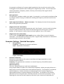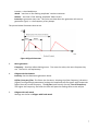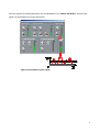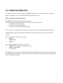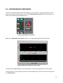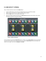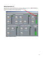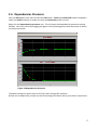
1
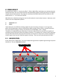
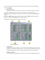
EZdok CAMERA ADDON
‘EZCA’
for
Microsoft Flight Simulator X
Advanced Effects Manual
1
CONTENTS
Chapter
Title
Page Number
1
Preface
3
2
RND effect
4
2.1
Generators
4
2.2
Mixer-distributor
9
2.3
Profiles
11
2.4
Dependencies
processor
12
2.5
RND effect tutorial
14
2.6
Dependencies
Processor
17
2.7
OnGround Effect
18
2.8
OnAir Effect
19
3
DHM Effect
20
3.1
DHM effect settings
21
4
CR Effect
23
5
Acknowledgement
24
2
1. PREFACE
This manual describes the EZdok CAMERA ADDON (EZCA) effects engine, and its principle of
operation and settings. It is recommended that you first study the EZCA User Manual and make all
the necessary setup parameters and/or modifications in FSX and EZCA before reading and using this
document.
There are three types of effects in EZCA.
They are:
1.
RND,
2.
DHM and
3.
CR.
(Note: The following are abstracted from the User Manual):
RND (Random)
This is a random visual effect simulating the roughness of the (apron, runway, taxiway, grass airstrip,
concrete, etc) surface when the plane is moving on the ground, and the slight general turbulence
effect that occurs whenever the aircraft is airborne. This is a “visual only effect” i.e. it does not
take into account the current weather settings in FSX. This effect depends on the weight of the
aircraft and the type of the surface.
DHM (Dynamic Head Movements)
DHM simulates the movement of the pilot’s head caused by aircraft acceleration and deceleration
during taxiing, etc maneuvers, touchdowns, and turbulence. Unlike the RND setting, this effect
depends on the weather settings used in FSX. DHM is designed to be used with the Virtual Cockpit
cameras only.
CR (Camera Resonance)
This effect is similar to Dynamic Head Movement, and simulates the shaking of a camera attached
to the aircraft as it lands.
3
2. RND EFFECT
As stated earlier, RND is a “visual only effect”. EZCA in RND Effect mode does not calculate dynamic
head movements, but uses simple formulas and adjustable random number generators to simulate
complex physical phenomena. By using this technique the EZDOK add-on has little effect on FSX
performance, i.e. it is frame-rate friendly.
RND effect has individual settings for each aircraft and each virtual cockpit camera. Moreover, each
camera has two independent profiles:
1.
2.
OnGround and
OnAir
These determine the different shaking modes for when the plane is flying or is on the ground.
When switching between cameras with different RND settings, EZCA ensures a smooth transition
from one camera setting to another and avoids an uncomfortable “jerky” change.
The ability to independently set effects for all cameras makes EZCA very versatile and capable of
simulating various dynamic effects for different cameras. For example, for a camera that represents
the pilot we need smooth and precise fluctuations of the point of view, but for camera attached to
aircraft engine cowl you will need fast vigorous shaking. That can easily be achieved with EZCA.
2.1 GENERATORS
At the heart of the “RND effect” are three independent generators capable of generating composite
waveforms: They are Generators A, B, C.
Figure 1 Generators A, B & C
4
We need multiple generators because aircraft vibration and /or shaking is a mixture of different
sources, for example:
• Air turbulence,
• Engine vibration and
• Sporadic pilot movement, (the pilot is not a dummy and should be capable of movement).
So by using multiple generators we can simulate these effects with high reliability and
reproducibility. All of the generators are set up in the same way, so we will examine Generator A
settings.
Right-Click the RND button on the main EZCA window to open the RND effect settings window,
then right or left click the Generator A icon to open its settings.
Each generator (A, B or C) consists of several simple modules:
Figure 2 Generator A
1.
Sine generator:
This generates harmonic oscillations. It can be used to simulate shaking that has a periodic
character, e.g. simulation of engine vibrations. In the current version of EZCA the frequency
is independent of engine rpm. You can adjust frequency and level in the sine generator.
2.
Resonance generator:
The RG simulates damped oscillations that occur when an aircraft undergoes impact forces.
5
For example, oscillations of a camera rigidly attached to the aircraft or the action of the
landing gear shock absorbers after landing on a rough bumpy surface. You can adjust the
various parameters, (frequency, attack, intensity, and release) of the signal and the
generator level rate.
3.
Noise generator:
This generates a random rumble noise signal. For example, it can be used to simulate rolling
on a rough surface or flying in turbulence, including the frequency and level at which that
will occur.
4.
Total output level indicator. ‘Master out meter’. This displays the level of the composite
effect of the generator parameters.
5.
LFOgen with ‘hard’ attack effect:
This is a Low Frequency Oscillation generator with ‘hard’ attack. It can be used to simulate
the pilot's body movement due to the aircraft bumping whilst moving on a runway or
taxiway. A ‘hard’ attack is usually ‘faster and more vigorous’ than a ‘soft’ attack.
6.
LFOgen with ‘soft’ attack effect:
This is similar to LFOgen With ‘hard’ attack but has a softer effect in terms of dynamic
movement. It can be used to simulate the pilot's irregular body movements or movements
caused by slight turbulence during flight.
Generator Settings - Detailed Description
1.
Sine generator:
Frequency – frequency of harmonic oscillation.
Level – amplitude of oscillations.
Figure 3 Sine Wave
2.
Resonance Generator
Resonance is the tendency of a system to oscillate with larger amplitude at some
frequencies than at others.
Frequency: This generates the resonance or natural frequency of the EZCA camera
suspension system.
Natural Frequency
The term ‘natural frequency’ needs some explanation.
Every physical body or system has its own natural frequency. When you apply a force to a
body (mass) it starts to oscillate with some definite frequency. This frequency is called the
natural frequency. Further with little or no damping then the resonant frequency is
approximately equal to a natural frequency of the system. An example of this physical
phenomenon is a tuning fork that is used by musicians to tune their instruments. So, by
adjusting this value you set the frequency with which your camera will shake after, for
6
instance, a simulated bump.
Attack – sets how a ‘fast shaking amplitude’ reaches maximum.
Release – sets how a ‘fast shaking amplitude’ fades to zero.
Intensity or generator start rate. This value sets how often the generator will start to
generate a signal, i.e. the frequency of any bumps.
The picture below illustrates these terms.
Figure 4 Signal Generator
3.
Noise generator :
Frequency – Sets how often shaking occurs. The more the value, the more frequent they
are. The level is self explanatory.
4.
LFOgen with hard attack:
Intensity: See the Resonance generator above.
LPfilter (Low-pass filter: This filters the vibrations, allowing slow (low frequency) vibrations
(signals) and significantly attenuates (reduces the amplitude of) the signals with frequencies
higher than the cut-off frequency. The LP filter knob actually sets the ‘Cut-off Frequency’.
The higher the frequency, the faster the filter will pass the shaking effect to the output.
5.
LFOgen with soft attack
Settings are similar to LFOgen with hard attack
7
All of the signals of module generators are consolidated via the ‘Master Out Meter’ and the total
signal is transmitted to the mixer-distributor.
Figure 5 Consolidation of the signal
8
2.2 MIXER-DISTRIBUTOR
The Mixer-Distributor mixes the signals of A, B, & C generators and distributes them to all of the
degrees of freedom (i.e. the simulated 3D positions) of the camera.
What are ‘degrees of freedom’ (DOF)?
Each EZCA camera has 6 degrees of freedom (dof).
This means that the camera can move in a virtual 3-dimensional manner:
• (1st dof or X axis), left to right
• (2nd dof or Y axis), up and down
• (3rd dof or Z axis), forward and backward.
Each camera can also rotate around these 3 axes and that gives 3 additional degrees of freedom.
In EZCA we have made the following assumptions with respect to body movement, and head
rotation.
The first 3 degrees of freedom are called:
•
Body X,
•
Body Y, and
•
Body Z,
The final three degrees of freedom are called:
•
Head X (head rotation to left-right, or yaw),
•
Head Y - pitch, Head
•
Z – bank (roll)
Each generator has an effect on each of the 6 degrees of freedom of the camera. You can set how
this will impact on what you see and experience in the SIM by the use of the appropriate generator
knobs 1 (See picture below).
9
Figure 6 Generator Knobs
The Knobs are color coded i.e. they have the same color as the generators they relate to, i.e.
•
Red knob sets the level of the Generator A,
•
Green knob – Generator B level and the
•
Blue knob – Generator C level.
The total amount of the effect of the generators on a specific DOF is set with knob 2.
Note: The total strength of the effect is set with Global Gain knob.
Figure 7 Global Gain
10
2.3
PROFILES
The behavior of an airplane in flight and one on the ground is completely different, so it would be
incorrect to use the same effects for both situations. EZCA solves this problem by using two
profiles:
•
•
OnGround &
OnAir.
These two profiles are automatically loaded depending on the position of the plane. For example,
when the aircraft touches the ground the ‘OnGround’ profile is loaded and when it becomes
airborne the ‘OnAir’ profile is loaded. This changes all of the settings of the appropriate
generators. Note: All of the profiles are completely independent from each other.
To edit the profiles:
Enable the RND effect by left-clicking the ‘RND’ button on the main EZCA window. Right click the
same button to open the RND settings window. Click the Edit button to enter the ‘profiles edit
mode’. When you do this, two additional buttons will appears in the window:
•
OnGround and
•
OnAir.
These buttons are used to select which profile to edit.
Figure 8 Profile Editor
11
2.4 DEPENDENCIES PROCESSOR
In real terms, totally random vibration/shaking is not very realistic. Shaking depends on many
factors and changes during a flight. Our unique ‘Dependencies Processor’ allows emulation of
reality by introducing some ‘dependencies’.
Figure 9 Dependencies processor
Right click: ‘Dependencies processor’ button. Two adjustable graphs will be displayed:
Figure 10 Gain Curve & Hi-Pass Filter Curve
The upper graph (Gain curve) sets the dependence of shaking amplitude and aircraft speed.
The horizontal axis of the graph represents aircraft speed in kph, and the vertical axis represents
the Vibration gain.
12
Vibration gain is an amplification factor (gain) of the shaking amplitude.
Amplification
Factor Value
>1
<1
0
Shaking Amplitude
Increases
Decreases
No Shaking
The lower graph (Hi-Pass Filter Curve or Vibration smooth) sets the dependence of shaking
frequency and aircraft speed. It works like a low-pass filter that cuts off high-frequency part of the
signal. The higher the curve, the less of the high frequency components of the signal are
transmitted to the output, resulting in smoother and slower shaking. If the value is zero, the signal
goes to the output unchanged, i.e. no shaking.
The shape of the curves can be adjusted by dragging each of the plotting points i.e. the small green
circles with a mouse.
For example, if we want to simulate aircraft's shaking during take-off roll, we would want the
amplitude and frequency of bumps to increase with acceleration i.e. increasing speed from zero.
So we would move the green circles on the upper graph, i.e. adjust the slope of the curve upwards
with increasing speed, until we achieved the take-off vibration effect that suited the plane that we
were flying.
Note: The Dependency processor is completely disabled during tuning of the generators and mixerdistributor, i.e. Vibration gain=1, Vibration smooth=0
13
2.5 RND EFFECT TUTORIAL
This is a short tutorial on how to create RND effects:
•
•
•
•
Enable a RND effect by left-clicking the RND button on the main EZCA window.
Right click the same button to open the RND settings window.
Click the Edit button to enter profiles edit mode.
Pause the Flight Simulator and select the OnGround profile and set the knobs on the mixerdistributor as shown in the picture below.
Figure 11 Mixer Distributor
In this example the signal from Generator A has an effect on the HeadY, BodyY axes (up-and-down
movement and rotation of the camera) whereas the signal of Generator B moves and rotates the
camera to the right and to the left (BodyX and HeadX).
14
Noise Generator A:
Right-click icon A to open the Generator A settings window and enable only Noise Generator by
clicking the small green button in the ‘noise generator section.
Set the values as shown in the following picture.
Figure 12 Noise Generator A
15
Noise Generator B:
Open Generator B settings and repeat but use different values. See picture below.
Note: when you change the settings, the values are automatically saved.
So it is recommended to backup any settings before you experiment with them (i.e. Export to an
external file).
Figure 13 Noise Generator B
Note: when you change the settings, the values are automatically saved.
Congratulations!
You've just created effect similar to camera shake during the takeoff roll.
Now we will use Dependencies processor: to set the dependence of shaking on speed
16
2.6 Dependencies Processor
Click the Edit button once more to leave the Edit mode. (OnAir and OnGround buttons disappear).
Check the Profile indicator to make sure that the OnGround profile is active.
Right-click the Dependencies processor icon. This will open the dependencies processor settings
window. Form new curves by dragging the green circles (plotting points) with the mouse as shown
on the picture below.
Figure 14 Dependencies Processor
The above settings are pretty close to real life values for light GA airplanes.
Do feel free to experiment, maybe you will find settings that better satisfy your taste or experience.
17
2.7 OnGround Profile - Edit
We recommend the following sequence for editing the OnGround profile .
1.
2.
3.
4.
5.
Create and adjust the effect for the precise moment of takeoff using the generators and the
mixer-distributor.
Try to takeoff in the Flight Simulator with these settings.
Pause the simulator at the exact moment of takeoff.
Open the RND settings window, enter Edit mode, select the OnGround profile, and leave
Edit mode.
Open the ‘Dependencies processor settings window’. The small vertical Red line shows the
current speed, which in this instance is equal to the takeoff speed. Of course, take-off speed
depends on many factors, and it can be ignored in this instance.
Figure 15 OnGround effects
The upper graph (Gain Curve) in the above picture indicates that the shaking amplitude (or shaking
effect) increases with speed up to take-off speed. On the lower graph we can see that at low
speeds the shaking is smooth and slow, but the more the speed increases the faster and sharper
they become.
18
2.8 OnAir Profile - Edit
OnAir profile settings are adjusted in a similar way, but the settings will be completely different
because of different nature of the shaking in the air and on the ground. Creating shake effects in
the air is more complex. So if you cannot accomplish a result that suits you, import settings from a
similar aircraft with predefined settings and try to play with them and see what happens.
19
3. DHM EFFECT
The DHM effect simulates the pilot's body movement caused by forces affecting aircraft, for
example when the pilot operates the throttles, applies the brakes, makes turns, accelerates,
decelerates, flies through turbulence, etc.
(Note: the DHM effect takes into account the turbulence in weather settings used for FSX, but
because the FSX model of turbulence is very simplified, the EZCA DHM effect of turbulence is also
rudimentary. In terms of turbulence effects and landing an aircraft the RND effects are more
spectacular and realistic).
The DHM effects include:
•
•
•
•
Aerodynamic forces (lift and drag),
Gravity,
Engine thrust, and
Impact force.
These forces cause the aircraft to accelerate/decelerate in different directions and make the pilot
feel the so called inertial force. The Pilot's body not being a rigid object reacts to this force, i.e.
his/her head and body moves, and attempts to rotate. This is the same force that slams you back
into your seat if you accelerate fast in a powerful car or plane. To compensate for these forces the
pilot would contract and relax various muscles in an attempt to return the body to the neutral
(comfortable) position.
Because the body has a mass and is subject to an effect such as inertial force, once it starts to
move, it cannot stop moving immediately away from the neutral position and it continues to move
further away from this “comfort zone”. Hence, it requires considerable muscular co-ordination to
counteract the effect, and return to the neutral position.
This behavior is very similar to that of a pendulum, and the EZCA model using our unique DHM
effect is based on this and is quite realistic. However, we had to incorporate some modifications to
counteract the limitations of the FSX (SDK) dynamics calculations. Fortunately, we were able
introduce features on how a real-life human body might move and react. However, we had to
simplify the effect somewhat on order to reduce the effect on FSX performance and frame rates.
Note: The DHM effect works with the Virtual cockpit cameras and is the same for all of the
cameras. The only parameter that is individual is the Main effect level.
20
3.1 DHM effect settings
Figure 16 DHM Effects
1. Acceleration processing units for X, Y, and Z axes.
The inertial force is a function of acceleration (or G-load/GForce) of the aircraft. EZCA reads
acceleration values from FSX via Simconnect, processes them and then calculates movement
of a human head taking into account the pilot's body parameters (next item).
The components that you can change include:
Constant G-Load X, Y & Z and Impulse G-load X Y
For more versatility G-loads are divided into two components
• Constant G-load and
• Impulse G-load.
An example of a Constant G-load component is the force felt during steep banking turn and an
example of an Impulse G-load component is felt during fast tight maneuvers, i.e. it depends on
rate of change of acceleration.
Banking effect
This effect is similar to Angle of slope of a head from lateral G-load, but results from
banking the aircraft.
21
Limit Movements or Movement Limiter, X, Y, & Z
This is a ‘soft’ limiter for axes X, Y, & Z, simulating pilot's seat and seat belts.
2. Pilot's body parameters settings.
These parameters determine how the pilot's body reacts to the inertia forces.
The components that you can change include:
Release time for all G-Load impulses
This sets how the impulses fade.
Angle of slope of a head from lateral G-load:
During certain maneuvers that you experience lateral g-loads (g-Force) the head bends to
the left and to the right. This value sets the level of this effect
Head Resonance
This parameter has an effect on the number of oscillations that a head will experience
before it returns to the equilibrium after it has been deflected by inertia force. The higher
the value, the faster the head movement returns to “normal”.
Head Mass
This value can be described as pilot's head inertia. It sets how fast the head returns to the
neutral position after it has been deflected by inertia force. The higher the value for head
mass the slower the head moves, i.e. there will be lower frequency of oscillations that were
described earlier.
3. Landing effect settings.
The effects experienced during landing, e.g. the operation of shock absorbers of the landing
gear as the plane lands
The components that you can change include:
Landing Effect
• Level to X Axes - The Level of DHM effect for the X axis.
• Level to Y Axes - The Level of DHM effect for the Y axis.
Shock Absorber
• Sharpness
Sharpness sets the coefficient of viscosity of shock absorber fluid.
The higher the value, the faster oscillations fades
• Amplitude of Sharpness
Sets the shock absorber stroke.
4. Total effect level (Main Level).
The Total level of the DHM effect and this is unique for each camera.
22
4. Camera Resonance (CR) EFFECT
Figure 17 Camera Resonance Effect
The camera resonance effect works in a similar fashion to the resonance generator and uses the
same settings. Refer to page 6 of this manual for information.
23
5. Acknowledgment
We would like to thank Peter Hayes, Australia for the editorial support and for making valuable
additions to the manual.
24