1
MobileView
Machine Terminal
MT750
2727-M7P20D1P1
2727-M7P20D1Q2
2727-M7P20D1Q3
User Manual
Important User Information
Solid state equipment has operational characteristics differing from those of
electromechanical equipment. Safety Guidelines for the Application,
Installation and Maintenance of Solid State Controls (Publication SGI-1.1
available from your local Rockwell Automation sales office or online at
http://www.ab.com/manuals/gi) describes some important differences
between solid state equipment and hard-wired electromechanical devices.
Because of this difference, and also because of the wide variety of uses for
solid state equipment, all persons responsible for applying this equipment
must satisfy themselves that each intended application of this equipment is
acceptable.
In no event will Rockwell Automation, Inc. be responsible or liable for
indirect or consequential damages resulting from the use or application of
this equipment.
The examples and diagrams in this manual are included solely for illustrative
purposes. Because of the many variables and requirements associated with
any particular installation, Rockwell Automation, Inc. cannot assume
responsibility or liability for actual use based on the examples and diagrams.
No patent liability is assumed by Rockwell Automation, Inc. with respect to
use of information, circuits, equipment, or software described in this manual.
Reproduction of the contents of this manual, in whole or in part, without
written permission of Rockwell Automation, Inc. is prohibited.
Throughout this manual we use notes to make you aware of safety
considerations.
WARNING
!
ATTENTION
!
Identifies information about practices or
circumstances that can cause an explosion in a
hazardous environment, which may lead to personal
injury or death, property damage, or economic loss.
Identifies information about practices or
circumstances that can lead to personal injury or
death, property damage, or economic loss.
Attentions help you:
• identify a hazard
• avoid a hazard
• recognize the consequence
IMPORTANT
SHOCK HAZARD
Identifies information that is critical for successful
application and understanding of the product.
Labels may be located on or inside the drive to alert
people that dangerous voltage may be present.
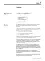
Preface
This preface provides information on:
• manual contents
• terminology
• intended audience
• intended uses
• European Communities (EC) Directive Compliance
• standards and agency certifications
• Rockwell Automation Support
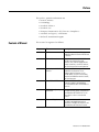
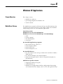
Contents of Manual
This manual is organized as follows:
Chapter
1
Title
Description
1
Overview
Gives a general overview of the
MobileView Machine Terminal MT750 and
its features.
2
Terminal Connections
Shows how to connect the MobileView
MT750 to the Junction Box, make
Ethernet, serial, and IrDA (keyboard and
printer) connections, use the PC Card slot,
and install the optional mounting bracket.
3
Configuring the MobileView
Terminal
Provides details on how to use the
MobileView Configuration Tool to
calibrate operating elements. It also
provides details on how to transfer data
between the MobileView terminal and PC,
and install programs.
4
Using RSView ME Station
Describes the RSView ME Station
software installed in the MobileView
2727-M7P20D1Q2 and 2727-M7P20D1Q3
terminals.
5
CE Thin Client Operating
Instructions
Gives instructions on how to start up,
configure Ethernet settings, and power off
the MobileView MT750 terminal. It also
gives details on how to start terminal
services.
6
Windows CE Applications
Describes the Windows CE software
installed in the MobileView terminal,
generation of Windows CE programs, and
the MobileView MT750 virtual channel.
Publication 2727-UM003D-EN-P
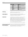
Preface
2
Chapter
Title
Description
7
Maintenance and
Troubleshooting
Provides information on cleaning, handling
and troubleshooting the MobileView
MT750 terminal.
A
Specifications
Gives specifications for the MobileView
MT750 terminal.
B
Available Fonts for Terminal
Applications
Provides information on pre-installed fonts
and available fonts for download for the
MobileView terminals.
Terminology
The MobileView Machine Terminal MT750 is referred to as the
MobileView terminal throughout this manual.
Intended Audience
This manual is for the individuals responsible for installing,
configuring, troubleshooting, and operating the MobileView Machine
Terminal MT750 in an industrial environment.
Intended Uses
The MobileView Machine Terminal MT750 may only be used for the
types of use described in this manual. This terminal has been
developed, manufactured, tested and documented in accordance with
ergonomic guidelines and the appropriate safety standards. If you
follow the instructions and safety precautions relating to the intended
use are properly observed, the MobileView MT750 does not, under
normal circumstances, represent a danger to the health of personnel
or a risk of damage to other property or equipment.
Observe national regulations for disposing of electronic components.
European Communities (EC)
Directive Compliance
Publication 2727-UM003D-EN-P
The product has the CE mark and is approved for installation within
the European Union and EEA regions. It has been designed and tested
to meet the following directives. In addition, the device meets the
Council Directive 98/37/EC as a safety component.
Preface
3
EMC Directive
This product is tested to meet the Council Directive 89/336/EC
Electromagnetic Compatibility (EMC) by applying the following
standards, in whole or in part, documented in a technical construction
file:
• EN 61000-6-4 EMC - Generic Emission Standard, Part 2 - Industrial
Environment
• EN 61000-6-4 EMC - Generic Immunity Standard, Part 2 - Industrial
Environment
• EN 61131-2 - Programmable Controllers Part 2 - Equipment
Requirement and Tests
This product is intended for use in an industrial environment.
A Declaration of Conformity is available upon request.
ATTENTION
!
The MobileView Machine Terminal MT750 meets the
requirements of EN 50081-2, Class A Emissions for
Industrial Environment. In the residential
environment, this product may cause high frequency
interferences. Corrective measures of the equipment
might be necessary.
Publication 2727-UM003D-EN-P
Preface
4
Publication 2727-UM003D-EN-P
Table of Contents
Preface
Contents of Manual . . . . . . . . . . . . . . . . . . . . . . . .
Terminology . . . . . . . . . . . . . . . . . . . . . . . . . . . . .
Intended Audience . . . . . . . . . . . . . . . . . . . . . . . .
Intended Uses. . . . . . . . . . . . . . . . . . . . . . . . . . . .
European Communities (EC) Directive Compliance
EMC Directive . . . . . . . . . . . . . . . . . . . . . . . . .
.
.
.
.
.
.
.
.
.
.
.
.
.
.
.
.
.
.
.
.
.
.
.
.
.
.
.
.
.
.
.
.
.
.
.
.
P-1
P-2
P-2
P-2
P-2
P-2
.
.
.
.
.
.
.
.
.
.
.
.
.
.
.
.
.
.
.
.
.
.
.
.
.
.
.
.
.
.
.
.
.
.
.
.
.
.
.
.
.
.
.
.
.
.
.
.
1-1
1-1
1-2
1-3
1-4
1-5
1-6
1-6
Chapter 1
Overview
Chapter Objectives . . . . . . . . . . . . . . . . . . . . . . .
Overview . . . . . . . . . . . . . . . . . . . . . . . . . . . . . .
MobileView MT750 Sample System Configuration.
Hardware Description . . . . . . . . . . . . . . . . . . . . .
Membrane Keypad . . . . . . . . . . . . . . . . . . . . . . .
Touch Screen . . . . . . . . . . . . . . . . . . . . . . . . . . .
MobileView MT750 Configurations. . . . . . . . . . . .
MobileView MT750 Accessories . . . . . . . . . . . . . .
.
.
.
.
.
.
.
.
Chapter 2
Terminal Connections
Chapter Objectives . . . . . . . . . . . . . . . . . . . . . . . . . . . . . . 2-1
Mounting and Connecting the Junction Box . . . . . . . . . . . . 2-2
DIN Rail Mounting . . . . . . . . . . . . . . . . . . . . . . . . . . . . 2-3
Connecting the MobileView to the Junction Box . . . . . . 2-4
Junction Box Pinout and Wiring . . . . . . . . . . . . . . . . . . 2-5
Power Supply Requirements. . . . . . . . . . . . . . . . . . . . . 2-6
MobileView Connection Cable . . . . . . . . . . . . . . . . . . . 2-7
MobileView Junction Box Cable . . . . . . . . . . . . . . . . . . 2-8
Accessing/Wiring the MobileView Connection Compartment 2-9
Removing the Back Cover . . . . . . . . . . . . . . . . . . . . . . 2-9
Connection Compartment Details . . . . . . . . . . . . . . . . . 2-10
Attaching the MobileView Connection Cable. . . . . . . . . 2-11
Connecting a Computer using the RS-232 Serial Port. . . . . . 2-12
Making an Ethernet Connection. . . . . . . . . . . . . . . . . . . . . 2-13
Using the PC Card Slot . . . . . . . . . . . . . . . . . . . . . . . . . . . 2-14
Inserting the PC Card . . . . . . . . . . . . . . . . . . . . . . . . . . 2-14
Removing the PC Card . . . . . . . . . . . . . . . . . . . . . . . . . 2-15
Connecting a Keyboard / Printer Using the IrDA Interface . 2-16
Installing the Mounting Bracket . . . . . . . . . . . . . . . . . . . . . 2-17
Chapter 3
Configuring the MobileView
Terminal
i
Chapter Objectives . . . . . . . . . . . . . . . . . . . . . .
Using the MobileView Configuration Tool . . . . .
Calibrating the Potentiometer . . . . . . . . . . . .
Adjusting Display and Touch Screen Settings
Setting the Handwheel to Zero . . . . . . . . . . .
Configure Keypad Settings . . . . . . . . . . . . . .
Configuring Startup Settings . . . . . . . . . . . . .
.
.
.
.
.
.
.
.
.
.
.
.
.
.
.
.
.
.
.
.
.
.
.
.
.
.
.
.
.
.
.
.
.
.
.
.
.
.
.
.
.
.
.
.
.
.
.
.
.
.
.
.
.
.
.
.
3-1
3-1
3-2
3-3
3-4
3-5
3-6
Publication 2727-UM003D-EN-P
Table of Contents
ii
Activating/Testing Pushbutton LEDs . . . . . . . .
Loading a New Image File . . . . . . . . . . . . . . .
Clearing the Registry . . . . . . . . . . . . . . . . . . .
Checking the Operating and Control Elements . . .
Transferring Data with a Personal Computer . . . .
Verifying Serial Port Availability . . . . . . . . . . .
Installing Microsoft ActiveSync Software . . . . .
Connecting the MobileView Terminal to a PC .
Disconnecting Communication . . . . . . . . . . . .
Installing Programs . . . . . . . . . . . . . . . . . . . . . . .
Saving Registry Settings . . . . . . . . . . . . . . . . . . . .
Power Settings . . . . . . . . . . . . . . . . . . . . . . . . . .
.
.
.
.
.
.
.
.
.
.
.
.
.
.
.
.
.
.
.
.
.
.
.
.
.
.
.
.
.
.
.
.
.
.
.
.
.
.
.
.
.
.
.
.
.
.
.
.
.
.
.
.
.
.
.
.
.
.
.
.
.
.
.
.
.
.
.
.
.
.
.
.
.
.
.
.
.
.
.
.
.
.
.
.
3-7
3-7
3-11
3-12
3-13
3-13
3-14
3-14
3-16
3-16
3-17
3-17
Chapter 4
Using RSView ME Station
Publication 2727-UM003D-EN-P
Chapter Objectives . . . . . . . . . . . . . . . . . . . . . . . . . . . . . . 4-1
Startup Options for RSView ME Station . . . . . . . . . . . . . . . 4-1
Start RSView without Loading or Running .MER Application
4-1
Start RSView and Load .MER Application . . . . . . . . . . . 4-2
Start RSView and Run .MER Application . . . . . . . . . . . . 4-2
Other Shortcut Paths for RSView ME Station . . . . . . . . . 4-3
Starting RSView ME from the desktop . . . . . . . . . . . . . . . . 4-4
Screen Buttons. . . . . . . . . . . . . . . . . . . . . . . . . . . . . . . 4-5
Input Panel . . . . . . . . . . . . . . . . . . . . . . . . . . . . . . . . . 4-6
Loading an ME Application . . . . . . . . . . . . . . . . . . . . . . . . 4-7
Running an Application. . . . . . . . . . . . . . . . . . . . . . . . . . . 4-8
Application Settings. . . . . . . . . . . . . . . . . . . . . . . . . . . . . . 4-8
Terminal Settings . . . . . . . . . . . . . . . . . . . . . . . . . . . . . . . 4-8
Networks and Communications . . . . . . . . . . . . . . . . . . . . . 4-9
KEPServer Port ID’s . . . . . . . . . . . . . . . . . . . . . . . . . . . 4-9
RSLinx Enterprise Communications . . . . . . . . . . . . . . . . 4-10
Network Connections. . . . . . . . . . . . . . . . . . . . . . . . . . 4-12
Diagnostic Setup . . . . . . . . . . . . . . . . . . . . . . . . . . . . . . . . 4-16
Message Routing . . . . . . . . . . . . . . . . . . . . . . . . . . . . . 4-16
File Management. . . . . . . . . . . . . . . . . . . . . . . . . . . . . . . . 4-17
Delete Files . . . . . . . . . . . . . . . . . . . . . . . . . . . . . . . . . 4-17
Copy Files . . . . . . . . . . . . . . . . . . . . . . . . . . . . . . . . . . 4-18
Font Linking . . . . . . . . . . . . . . . . . . . . . . . . . . . . . . . . . . . 4-20
Print Setup . . . . . . . . . . . . . . . . . . . . . . . . . . . . . . . . . . . . 4-21
Display, Alarm, and Diagnostic Print Setup . . . . . . . . . . 4-21
Startup Options. . . . . . . . . . . . . . . . . . . . . . . . . . . . . . . . . 4-23
RSView ME Station Startup . . . . . . . . . . . . . . . . . . . . . . 4-23
Time/Date/Regional Settings . . . . . . . . . . . . . . . . . . . . . . . 4-25
Date . . . . . . . . . . . . . . . . . . . . . . . . . . . . . . . . . . . . . . 4-25
Time . . . . . . . . . . . . . . . . . . . . . . . . . . . . . . . . . . . . . . 4-26
Time Zone. . . . . . . . . . . . . . . . . . . . . . . . . . . . . . . . . . 4-27
Table of Contents
iii
Chapter 5
CE Thin Client Operating
Instructions
Chapter Objectives . . . . . . . . . . . . . . . . . .
Starting Up/Powering On the Terminal . . .
Setting Auto Start . . . . . . . . . . . . . . . . . . .
Configuring Ethernet Network Settings. . . .
Saving Registry Settings . . . . . . . . . . . . . . .
Starting Terminal Services . . . . . . . . . . . . .
Shutting Down/Powering Off the Terminal
Setting the Date and Time . . . . . . . . . . . . .
.
.
.
.
.
.
.
.
.
.
.
.
.
.
.
.
.
.
.
.
.
.
.
.
.
.
.
.
.
.
.
.
.
.
.
.
.
.
.
.
.
.
.
.
.
.
.
.
.
.
.
.
.
.
.
.
.
.
.
.
.
.
.
.
.
.
.
.
.
.
.
.
.
.
.
.
.
.
.
.
.
.
.
.
.
.
.
.
.
.
.
.
.
.
.
.
5-1
5-1
5-2
5-2
5-3
5-4
5-5
5-5
.
.
.
.
.
.
.
.
.
.
.
.
.
.
.
.
.
.
.
.
.
.
.
.
.
.
.
.
.
.
.
.
.
.
.
.
.
.
.
.
.
.
.
.
.
.
.
.
.
.
.
.
.
.
.
.
.
.
.
.
.
.
.
.
.
.
.
.
.
.
.
.
.
.
.
.
.
.
.
.
.
.
.
.
.
.
.
.
.
.
.
.
.
.
.
.
.
.
.
.
.
.
.
.
.
.
.
.
.
.
.
.
.
.
.
.
.
.
.
.
6-1
6-1
6-2
6-3
6-4
6-4
6-4
6-4
6-5
6-7
Chapter 6
Windows CE Applications
Chapter Objectives . . . . . . . . . . . . . . . . . .
MobileView Software . . . . . . . . . . . . . . . .
Generating Programs for Windows CE . . . .
Virtual Channel . . . . . . . . . . . . . . . . . . . . .
Getting Started. . . . . . . . . . . . . . . . . . .
Activating the Virtual Channel . . . . . . .
Events Causing the Client to Send Data.
Events of Server. . . . . . . . . . . . . . . . . .
Data Transmission . . . . . . . . . . . . . . . .
Example: Interface on Server . . . . . . . .
Chapter 7
Maintenance and Troubleshooting Chapter Objectives . . . . . . . . . . . . . . . . . . . . . . . . . . . . . . 7-1
Cleaning the MobileView MT750 Terminal .
Handling the MobileView MT750 Terminal.
Troubleshooting the Terminal . . . . . . . . . .
Providing Technical Support Information . .
.
.
.
.
.
.
.
.
.
.
.
.
.
.
.
.
.
.
.
.
.
.
.
.
.
.
.
.
.
.
.
.
.
.
.
.
.
.
.
.
.
.
.
.
.
.
.
.
7-1
7-2
7-3
7-4
.
.
.
.
.
.
.
.
.
.
.
.
.
.
.
.
.
.
.
.
.
.
.
.
.
.
.
.
.
.
.
.
.
.
.
.
.
.
.
.
.
.
.
.
.
.
.
.
A-1
A-1
A-2
A-2
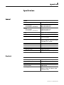
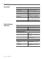
Appendix A
Specifications
General . . . . . . . . . . . . . . . . . . . .
Electrical. . . . . . . . . . . . . . . . . . . .
Environmental . . . . . . . . . . . . . . .
Standard and Agency Certifications
.
.
.
.
.
.
.
.
.
.
.
.
.
.
.
.
.
.
.
.
.
.
.
.
Appendix B
Available Fonts for Terminal
Applications
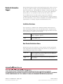
Downloading Fonts to Terminal . . . . . . . . . . . . . . . . . . . . B-1
VersaView CE Accessories CD . . . . . . . . . . . . . . . . . . . . . . B-2
RSView Machine Edition Fonts CD. . . . . . . . . . . . . . . . . . . B-2
Index
Publication 2727-UM003D-EN-P
Table of Contents
iv
Publication 2727-UM003D-EN-P
Chapter
1
Overview
Chapter Objectives
This chapter covers the following topics:
• overview
• hardware description
• membrane keypad
• touch screen
• terminal configurations
• terminal accessories
Overview
The MobileView products are a family of human machine interface
devices with a rugged design and Windows-CE compatible
electronics.
Using a high-performance Intel StrongARM processor and providing
an Ethernet interface, the MobileView Machine Terminal MT750 is
ideal for a variety of applications including:
• operator panel for machines and plants
• teach and programming panel for robots
• test, maintenance, and startup
All tasks can be solved graphically and in color. Operation is intuitive,
using a touch screen with symbol-controlled sequences.
Instead of a floppy or hard disk drive, which are not suitable for harsh
environmental conditions, the MobileView MT750 uses scalable
FLASH and RAM banks. Functionality is easily expanded using PC
cards Type I, II, and III.
The MobileView MT750 connects as a client to a Windows NT or
Windows 2000 server. It also provides a Windows CE platform for
applications generated with common visualization tools, Visual Basic
or Visual C++, and the CE 4.x Software Developers Kit (SDK) included
on the product CD.
The MobileView Machine Terminal MT750 (Catalog Number
2727-M7P20D1Q2 and 2727-M7P20D1Q3) supports RSView Machine
Edition Software.
The MobileView MT750 easily adapts to specific applications using
configurable operating and control elements.
1
Publication 2727-UM003D-EN-P
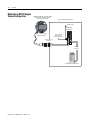
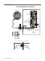
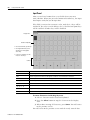
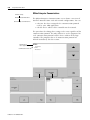
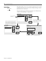
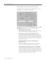
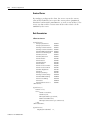
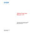
Overview
MobileView Machine Terminal MT750
running as CE Thin Client and/or
Custom CE Applications
Ru
n
MobileView MT750 Sample
System Configuration
Typical System Control Cabinet
24V dc Power
Err
or
1-2
ESC
7
8
9
4
5
6
1
2
3
.
0
-
MobileView
Junction Box
K ETOP
24V D C
ON LY
+24V
TER M IN AL IN
GND
ES1+
ES1ES2+
5, 10, 15, 20 meter mobile
Connection Cable
ES2ED1+
ED1-
Safety Equipment
Connections for
MobileView G750 only
ED2+
ED2-
R S422 OUT
+24V
GND
ES1+
ES1ES2+
Discrete/Ethernet
Connection
ES2ED1+
ED1ED2+
ED2-
ETH ER N ET O U T
Ethernet
Connection
Local or Remote
Windows NT or 2000 Server
Publication 2727-UM003D-EN-P - Month Year
Overview
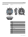
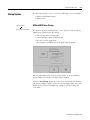
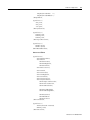
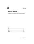
Hardware Description
1-3
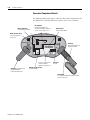
The following illustration shows the location of key hardware
components.
2
12
1
11
3
9
4
8
5
7
6
15
13
14
10
1
Potentiometer with 0-127 linear resolution (option)
2
Electronic handwheel with 50 pulses/rev, -32768 to +32768 (option)
3
Emergency stop switch location (optional only on the MobileView Guard G750
Terminals)
4
Membrane keypad with tactile feedback - standard Windows keyboard operation
5
Illuminated momentary push button, normally open, OFF marking, yellow LED (option)
6
3-position key switch (option)
7
Illuminated momentary push button, normally open, ON marking, yellow LED (option)
8
7.7 inch VGA (640 x 480 pixels) passive matrix color LCD display with analog resistive
touch screen
9
Enabling switch location - one each side of handle (optional only on the MobileView
Guard 750 Terminals)
10
IrDA keyboard/printer interface, 9600 or 115.2K baud
11
Handle for left or right-hand operation
12
Single slot PC card interface for Type I, II and III cards (option)
13
Strain relief for connection cable (shipped with cable)
14
Back cover to connection compartment
15
Plug for cable outlet when not used (meets degree protection IP54)
Publication 2727-UM003D-EN-P
1-4
Overview
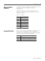
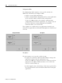
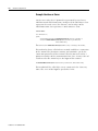
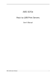
Membrane Keypad
The MobileView terminal has a membrane keypad with stainless steel
dome switches for tactile feedback.
Function Keys
F1 - F12
Tab Left/Right Keys
Shift and Ctrl Keys
Numeric,
Period,
Minus
Keys
Backspace and Esc Key
Page Up/Down
Home/End
Enter Key
Alt Key
The keys on the keypad operate identically to a Windows PC
keyboard with the exception of Tab Left and the ALT-Arrow key
combinations. Most standard 2-key combinations are supported
including some 3-key combinations. The table below shows the
Windows virtual key codes for each key.
Publication 2727-UM003D-EN-P - Month Year
Keypad Key
Windows Virtual Key Code
Numeric keys 0 - 9
VK_NUMPAD0 through VK_NUMPAD9
. (period)
VK_DECIMAL
- (minus)
VK_SUBRACT
Arrow (left/right/up/down)
VK_LEFT/VK_RIGHT/VK_UP/VK_DOWN
Enter
VK_RETURN
Backspace
VK_BACK
ALT+Up arrow (PG UP)
VK_PRIOR
ALT+Down arrow (PG DN)
VK_NEXT
ALT+Left arrow (PG HOME)
VK_HOME
ALT+Right arrow (PG END)
VK_END
Tab Left key
VK_LSHIFT+VK_TAB
Tab Right key
VK_TAB
SHIFT key
VK_LSHIFT
CTRL
VK_LCONTROL
F1 - F12 function keys
VK_F1 through VK_F12
Overview
Keypad Key
Windows Virtual Key Code
ESC key
VK_ESCAPE
ALT key
VK_MENU
1-5
Options:
Illuminated push button, left
Key switch, left
Key switch, right
Illuminated push button, right
Touch Screen
VK_F13
VK_F14
VK_F15
VK_16
The touch screen is calibrated before shipment. No further calibration
is required.
ATTENTION
!
Do not use a sharp object, such as a screw driver to
operate the touch screen. Using sharp objects may
damage the touch screen.
Publication 2727-UM003D-EN-P
1-6
Overview
MobileView MT750
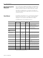
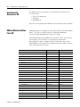
Configurations
The MobileView MT750 terminal is available in 3 configurations. The
table below lists each configuration by catalog number and the
included features.
Features
2727-M7P20D1P1
2727-M7P20D1Q2
7.7 Inch VGA Display
Yes
IrDA Interface
Yes
3-Position Enable
Switch
No
2-Circuit E-Stop
No
(Position 3)
Memory
PC Card Slot
2727-M7P20D1Q3
16MB DRAM
32MB Flash
64MB DRAM/64MB Flash
No
Yes
Communications
10Base-T Ethernet
Push Button with OFF
Marking - Position 5
Operating Elements
No
No
Key Switch - Position 6
Push Button with ON
marking - Position 7
Windows CE
Operating System
RSView Machine
Edition
Yes
No
Thin Client
Application
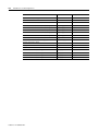
MobileView MT750
Accessories
Yes
Yes
The following accessories are available for the MobileView MT750
terminal.
Catalog Number
Description
2727-MRT5
MobileView Connection Cable (5 meter /16.4 ft) - connects the MobileView terminal to the Junction Box Cable.
2727-MRT10
MobileView Connection Cable (10 meter /32.8 ft) - connects the MobileView terminal to the Junction Box Cable
2727-MRT15
MobileView Connection Cable (15 meter /49.2 ft) - connects the MobileView terminal to the Junction Box Cable.
2727-MRT20
MobileView Connection Cable (20 meter/65.6 ft) - connects the Mobileview terminal to the Junction Box cable.
2727-MRJB1
MobileView Junction Box - provides controller, Ethernet and power supply connections.
2727-MREX1
MobileView Junction Box Cable (2 meter / 6.5 ft) - connects the MobileView Connection Cable to the Junction Box.
2727-MRC1
MobileView Download Cable (4 meter /13.1 ft) - connects between the MobileView terminal to a PC.
2727-MRMB1
MobileView Mounting Bracket for stationary operation or storing the MobileView terminal.
2727-MRSDK1
MobileView SDK file set for Windows CE development
Publication 2727-UM003D-EN-P - Month Year
Chapter
2
Terminal Connections
Chapter Objectives
This chapter shows how to connect devices to the MobileView terminal,
including:
•
•
•
•
•
•
•
1
mounting and connecting the MobileView Junction Box
accessing and wiring the MobileView connection compartment
connecting a computer using the RS-232 Port
making an Ethernet connection
using the PC card slot
connecting a keyboard/printer using the IrDA interface
installing the MobileView Mounting Bracket
Publication 2727-UM003D-EN-P
2-2
Terminal Connections
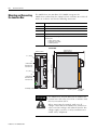
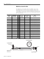
Mounting and Connecting
the Junction Box
The MobileView Junction Box (2727-MRJB1) integrates the
MobileView terminal into the control system. It mounts on a DIN rail
inside an enclosure and has the following connectors:
Connectors
Description
S1
RJ-45 jack for connecting the MobileView data lines.
S2
9-pin DSUB female connector (for future use).
S3
RJ-45 jack to Ethernet network.
X1
12-pin male connector for connecting the Junction Box Cable.
X2
12-pin male connector (shipped with a female terminal block connector) for
connecting the:
• 24V dc power supply
• emergency stop switch
• enabling switches
Junction Box
150 mm (5.91 in)
108 mm (4.25 in)
60 mm (2.36 in)
24V D C
ON LY
Pin 1, 24V dc
+24V
TER M IN AL IN
GND
ES1+
S1
ES1-
Pin 1, 24V dc
ES2+
ES2ED1+
ED1ED2+
ED2-
R S422 OUT
S2
+24V
GND
ES1+
X2
(with Female
Terminal Block
Connector K4)
162 mm (6.4 in.)
X1
(with Female
Terminal Block
Connector K3)
ES1ES2+
ES2ED1+
ED1ED2+
ED2-
ETH ER N ET O U T
S3
Grounding Screw
DIN Rail Latch
ATTENTION
!
Publication 2727-UM003D-EN-P
Grounding Screw
Strain Relief
for Cable
The MobileView Junction Box and the MobileView
terminal meet the safety class III in accordance with
EN 61131-2 and EN 50178.
When connecting the terminal, make sure all
voltages connected to the MobileView terminal are
safety extra low voltages and isolated from the low
voltage supply system by a safety transformer or a
similar safety component.
Terminal Connections
2-3
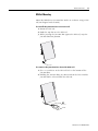
DIN Rail Mounting
Mount the MobileView Junction Box inside an enclosure using a DIN
rail (not shipped with terminal).
To install the Junction Box on a DIN rail:
1. Mount the DIN rail.
2. Hook the top slot over the DIN rail.
3. While pressing the Junction Box against the DIN rail, snap the
Junction Box into position.
To remove the Junction Box from the DIN rail:
1. Place a screwdriver in the DIN rail latch at the bottom of the
Junction Box.
2. Holding the Junction Box, pry downward on the latch until the
Junction Box is released from the DIN rail.
Publication 2727-UM003D-EN-P
2-4
Terminal Connections
Connecting the MobileView to the Junction Box
MobileView Junction Box
Control Cabinet
MobileView Terminal
24V D C
ON LY
Pin 1, 24V dc
+24V
TER M IN AL IN
n
Ru
Er
ro
r
GND
ESC
X1/K3
MobileView
Terminal Connections
S1
ES1+
ES1ES2+
ES2ED1+
ED1-
7
8
9
4
5
6
ED2+
1
2
3
ED2-
.
0
-
R S422 O U T
KE TOP
S2
Pin 1, 24V dc
+24V
GND
X2/K4
Safety Equipment
Connections (for
Mobileview G750 only)
ES1+
ES1ES2+
ES2ED1+
ED1ED2+
ED2-
ETH ER N ET O U T
S3
maximum wall
thickness 5 mm (0.2 in)
Junction Box Cable
2 m (6.5 ft)
Use Grounding Screw to
connect Earth Ground to
Junction Box.
24 mm
(0.94 in)
Junction Box Cable
Tie Wire
25 mm (±0.1)
(0.98 in ±0.0039)
Cable Clearance on both sides of Enclosure Wall
130mm (5.12 in)
Connection Cable
Publication 2727-UM003D-EN-P
10 Base-T Connection
to Ethernet Network
K1
Connection
100 mm (3.94 in)
Junction Box Cable
Terminal Connections
2-5
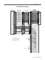
Junction Box Pinout and Wiring
MobileView
S19 K3
MobileView
Connection Cable
Junction Box
Cable
K1
6
pink
1
pink
7
black
green-brown
2
black
green-brown
white-green
grey-pink
4
6
1
red-blue
brown
7
red-blue
brown
2
yellow
8
yellow
3
green
12
green
4
grey
17
grey
5
violet
11
violet
8
9
10
11
3
5
MobileView
Junction Box
K3
white-green
grey-pink
X1
1 24V dc
2 GND_IN
3 E-Stop, circuit 1, pos.*
4 E-Stop, circuit 1, neg.*
9
X2
1
2
3
4
K4
+24V
GND
ES1+
ES1-
5 E-Stop, circuit 2, pos.*
5
6 E-Stop, circuit 2, neg.*
6
7 Enabling Sw. circuit 1, pos.* 7
ES2+
ES2-
8 Enabling Sw. circuit 1, neg.* 8
9 Enabling Sw. circuit 2, pos.* 9
ED1-
10 Enabling Sw. circuit 2, neg.* 10
11 Not Used
11
12 Not Used
12
ED2-
ED1+
ED2+
10
S4 K2
K2 S1
1
blue
2
white
3
orange
13
blue
1
14
white
2
15
orange
3
16
4
5
6
red
red
6
7
8
S2
1
2
3
4
* Junction Box connections are
for connection to MobileView
Guard G750 Terminals only.
5
Future Use
6
7
8
9
S3
TD+
TDRD+
1
2
3
4
To Ethernet Network
5
RD-
6
7
8
Publication 2727-UM003D-EN-P
2-6
Terminal Connections
Power Supply Requirements
Electrical Specifications
24V dc Power Supply
Use a 24V dc Safety Extra Low Voltage power
supply.
Supply Voltage Range: 18V dc to 32V dc
Current Consumption: 300mA at 24V dc
Peak Inrush Current: 5.6 A maximum
Grounding
Connect Earth Ground to the Junction Box using
the Earth Ground Screw (shown on previous
page 2-4).
ATTENTION
!
Publication 2727-UM003D-EN-P
• The device meets the safety class III in
accordance with EN 61131-2 and EN 50178. The
24V power supply for the equipment must
provide appropriate isolation between the
safety-extra-low-voltage circuits and
dangerous-contact voltage circuits (for example,
by safety transformers or similar facilities).
• The power supply circuit must be protected with
a 3.15 A fuse.
• The nominal supply voltage of the MobileView
terminal (without MobileView Connection Cable)
is 24V dc (supply voltage range: 18-32V dc) with
a typical input current of 300 mA.
When planning the power supply, consider the
voltage drop in the connection cable.
Specifications of power supply lines in the
connection cable are:
- Cross section: AWG24 (0.24mm2)
- Material: zinc-coated copper strand
- Line resistance: <90 Ohm/km (<145 Ohm/mile)
Terminal Connections
2-7
MobileView Connection Cable
The Mobile Connection Cable (2727-MRTxx) connects the MobileView
terminal to the MobileView Junction Box Cable (2727-MREX1). The
Connection Cable is 5, 10, 15, or 20 meters (6.4, 32.8, 49.2 or 65.6 ft). This
cable withstands water, cleaning agents, motor oil, drilling oils, grease,
lubricants and condensates containing hydrochloric acid.
K1
17-pin Circular
Connector Pin #
MobileView
Connection Cable
Wire Color
K3, 11-pin Female
Connector
to S19 in
Terminal
K2, 8-pin
RJ-45 Jack
Ethernet to S4 in
Terminal
Signal
Description
1
pink
-->>
6
-
24V DC
2
black
-->>
7
-
GND_IN
3
green-brown
-->>
8
-
E-stop, circuit 1, positive*
4
white-green
-->>
9
-
E-stop, circuit 1, negative*
5
grey-pink
-->>
10
-
E-stop, circuit 2, positive*
6
red-blue
-->>
11
-
E-stop, circuit 2, negative*
7
brown
-->>
1
-
enabling switch, circuit 1, positive*
8
yellow
-->>
2
-
enabling switch, circuit 1, negative*
12
green
-->>
3
-
enabling switch, circuit 2, positive*
17
grey
-->>
4
-
enabling switch, circuit 2, negative*
9
bridge to pin 10
-->>
-
-
not used
10
bridge to pin 9
-->>
-
-
not used
11
violet
-->>
5
-
not used
13
blue
-->>
-
1
TD+ (transmit)
14
white
-->>
-
2
TD- (transmit)
15
orange
-->>
-
3
RD+ (receive)
16
red
-->>
-
6
RD- (receive)
* For connection to MobileView Guard G750 only.
K1, 17-pin circular connector
view from connector side
11
10
1
2
12
16
13
9
K3, 11-pin
female connector
to S19 at MobileView terminal
17
3
14
15
8
4
5
7
6
K2, 8-pin
RJ-45 jack to S4
at MobileView
terminal
5, 10, 15, or 20 meter (6.4, 32.8, 49.2, or 65.6 ft)
Publication 2727-UM003D-EN-P
2-8
Terminal Connections
MobileView Junction Box Cable
The MobileView Junction Box Cable (2727-MREX1) connects the
Junction Box to the circular jack in the wall of the enclosure. The
cable length is 2 meters (6.5 ft.). When the MobileView terminal is not
connected to the Junction Box, the dust cover provides protection for
the 17-pin connector.
K2, 8-pin
RJ-45 Jack
to S1 at
Junction Box
K3, 12-pin
Terminal Block
to X1 at
Junction Box
-->
-
1
24V DC
black
-->
-
2
GND_IN
3
green-brown
-->
-
3
E-stop, circuit 1, positive*
4
white-green
-->
-
4
E-stop, circuit 1, negative*
5
grey-pink
-->
-
5
E-stop, circuit 2, positive*
6
red-blue
-->
-
6
E-stop, circuit 2, negative*
7
brown
-->
-
7
enabling switch, circuit 1, positive*
8
yellow
-->
-
8
enabling switch, circuit 1, negative*
12
green
-->
-
9
enabling switch, circuit 2, positive*
17
grey
-->
-
10
enabling switch, circuit 2, negative*
9
-
-->
-
10
-
-->
-
12
not used
11
violet
-->
-
11
not used
13
blue
-->
1
-
TD+ (transmit)
14
white
-->
2
-
TD- (transmit)
15
orange
-->
3
-
RD+ (receive)
16
red
-->
6
-
RD- (receive)
K1, 17-pin
Circular Jack
Pin #
MobileView
Junction Box Cable
Wire Color
1
pink
2
Signal
Description
not used
* For connection to MobileView Guard G750 only.
K1, 17-pin circular jack
view from connector side
1
11
2
K3, 12-pin connector
for terminal block X1
at Junction Box
12
10
16
13
3
9
17
15
14
4
8
7
5
6
Dust Cover
K2, 8-pin RJ-45 jack
Ethernet for S1
at Junction Box
Publication 2727-UM003D-EN-P
2 meter (6.5 ft)
K1, 17-pin circular jack
mounts to enclosure
Terminal Connections
Accessing/Wiring the
MobileView Connection
Compartment
2-9
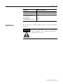
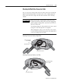
Removing the Back Cover
This section shows how to remove the back cover of the MobileView
terminal. Once the back cover is removed, you have access to the
area which contains all of the connectors.
ATTENTION
!
Turn off the power supply before removing the back
cover of the MobileView terminal.
When the back cover is removed, the MobileView
terminal is sensitive to electrostatic discharge (ESD).
1. Place the terminal on a stable, flat surface.
2. Remove the 6 screws that secure the back cover to the MobileView
terminal.
3. Carefully lift off the back cover and place it on a secure surface.
Back Cover
Publication 2727-UM003D-EN-P
2-10
Terminal Connections
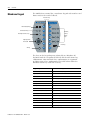
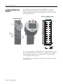
Connection Compartment Details
The following illustration shows what the connection compartment of
the MobileView terminal looks like with the back cover removed.
Reset Button
for rebooting Windows CE.
All data not flushed to Registry or
saved to Flush Storage is lost.
RS-232 Serial Port
for downloading software.
Main connector (S19)
for power supply and
control lines
Ethernet label
Ethernet (MAC) address
Pin 1
Serial
port
R eset
S19
B4
2250-00001
00:60:
B5:06:00:
AABBC
C D01
D EEFF
Important: Install plug on the
unused MobileView
Connection Cable outlet.
B6
B3
S4
Ethernet
B2
Cable Tag
allows the terminal to be
uniquely identified.
S6,
COM -M odul
B5
Position of switches does
not affect terminal
operation (for future use)
Ethernet connector (S4)
for data exchange
Connector
not used
Strain Relief
for connecting MobileView Connection Cable
(on left or right side)
Publication 2727-UM003D-EN-P
Terminal Connections
2-11
Attaching the MobileView Connection Cable
You can attach the Connection Cable on either side of the terminal for
right or left-hand operation. To relocate the cable, simply grasp the
strain relief and/or the plug and slide off of mount with a rocking
motion.
Make sure the K3, 11-pin female connector clicks
completely into S19, Main Connector when plugged in.
Ensure proper seating of K2, 8-pin RJ-45 jack into S4,
Ethernet Connector.
IMPORTANT
To avoid pinching the cable with the back cover, avoid
laying the cable on top of the T-supports.
After routing the cable, secure the back cover to the
terminal.TomaintainIP54degreeprotection,tightenthe6
screws to a torque of 4.42 in-lb.
Attaching Connection Cable on Right Side
Avoid routing cable
over T-support.
S6,
COM -M odul
S19
Main Connector
S4, Ethernet Connector
S6,
C OM -M odul
Attaching Connection Cable on Left Side
Avoid routing cable
over T-support.
S4, Ethernet Connector
S19, Main Connector
Publication 2727-UM003D-EN-P
2-12
Terminal Connections
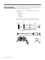
Connecting a Computer
using the RS-232 Serial Port
Use the RS-232 Serial Port in the MobileView terminal to download
software or to modify/transmit data between the MobileView terminal
and computer using Active Sync software.
The RS-232 Serial Port uses the following fixed communication
parameters:
• 115200 baud
• 8 data bits
• 1 stop bit
• No parity
• No handshake
The MobileView Download Cable (Catalog Number 2727-MRC1)
connects the MobileView terminal to the serial port of your computer.
MobileView
10-pin Latch
(male connector)
MobileView
Serial Port S2 Connector
(female)
1
1*
2*
2
ActiveSync
Tx
3
5
To
9
ActiveSync
Rx
ActiveSync
7*
9
10
Gnd
PC
9-pin DSUB
(female connector)
1
6
2
3
PC 9-pin
(male connector)
To
4
5
* Pins 1, 2 and 7 are connected together on the CPU board in the MobileView terminal. They are used for the
ActiveSync signal. If you make your own cable, do not eliminate these 3 wires.
9
Ader1
R eset
B5
B4
2250-00001
00:60:
B5:06:00:
AABBC
C D01
D EEFF
B2
Ethernet
1
B6
S6,
COM -M odul
Serial
port
Publication 2727-UM003D-EN-P
1
4 meters (13.12 feet)
Pin 1
B3
Serial
Port
Terminal Connections
Making an Ethernet
Connection
2-13
The MobileView terminal is equipped with a 10Base-T interface which
supports TCP/IP protocol at 10MBaud for half-duplex
communications.
The Ethernet connector at S3 on the Junction Box provides a
connection to an Ethernet network. The connector uses an 8-pin
modular jack connector.
Pinouts are as follows:
Using the PC Card Slot
Pin #
Ethernet Signal
1
TD+
2
TD-
3
RD+
4
Not Used
5
Not Used
6
RD-
7
Not Used
8
Not Used
The PC card slot is a factory installed option and supports Type I, II,
and III PC cards. The following PC cards are available from
Allen-Bradley. The terminal does not support SRAM cards, CardBus
cards, or cards that use 12 volts for programming.
Catalog No.
Description
2711-NM28
8M flash ATA card for storing applications.
2711-NM216 16M flash ATA card for storing applications.
2711-NM232 32M flash ATA card for storing applications.
Publication 2727-UM003D-EN-P
2-14
Terminal Connections
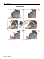
Inserting the PC Card
1
Lay the MobileView with the display facing down onto a flat, clean
table, preferably on Electrostatic Discharge (ESD) pad. Take care
not to damage the terminal and its elements.
2
Unlock the PC card cover as shown (until
the locking lever is released)
3
1
4
Attention:
Check the condition
and position of the
cover seal before
closing the PC card
cover.
Ejection button
Attention:
Verify that this corner
is inserted into the slot
on the side of the
ejection button.
Insert the PC card until it locks in and the ejection
button pops out.
2
1. Open the cover.
2. Insert the PC card as shown.
6
5
1
3
Must snap
completely.
2
1. Close the cover.
2. and 3. Lock the cover as shown.
Publication 2727-UM003D-EN-P
Press down the cover until it snaps in completely to
meet the protection degree IP54.
Terminal Connections
2-15
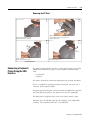
Removing the PC Card
2
1
1
3
2
1. Open the PC card cover.
2. Press the ejection button of the PC card slot.
3. Remove the PC Card
Unlock the PC card cover as shown
(until the locking lever is released).
3
4
1
3
Must
snap
completely.
2
1. Close the cover.
2. and 3. Lock the cover as shown.
Connecting a Keyboard /
Printer Using the IrDA
Interface
Press down the cover until it snaps in completely to meet
the protection degree IP54.
The IrDA keyboard/printer interface is built into the lower rim of the
MobileView terminal (see page 1-3) and supports communication
with:
• keyboards
• printers
The port is located for convenient operation with an IrDA keyboard.
To use a standard PC keyboard with the IrDA port, you must use a
converter (PS2 keypad to IrDA).
To print using the IrDA port, you must orient the MobileView towards
the IrDA port of the printer. The printer must be PCL compatible.
The IrDA port is assigned to the COM 3 or COM 4 interface port.
Protocol: Only the HP-SIR (Low Speed) coding is used (LPM Mode
enabled). The maximum baud rate is 115.2K baud.
Publication 2727-UM003D-EN-P
2-16
Terminal Connections
Installing the Mounting
Bracket
The MobileView Mounting Bracket (2727-MRMB1) is used for
stationary operation or storage of the MobileView terminal. The
following illustration shows the mounting bracket with and without
the terminal mounted.
Dimensions and Mounting Holes
120 mm (4.72 in)
Height Adjustment Plate
6m
12
md
ia. (
mm
0.24
in)
dia
. (0
.4 7
Carrier
150 mm (5.91 in)
28 mm
(1.1 in)
526 mm (20.71 in)
22 mm (0.87 in)
20 mm
(0.79 in)
12 mm (0.47 in)
550 mm (21.65 in)
in)
MobileView
Connection
Cable
Holder
The carrier is adjustable in 8 positions over a height of 320 mm (12.60
in). It is important to attach the carrier at all 4 points on the height
adjustment plate. Mount the cable holder on the carrier using the
screws shipped with the bracket.
Use suitable screws (not shipped with product) to mount the height
adjustment plate.
Publication 2727-UM003D-EN-P
Chapter
3
Configuring the MobileView Terminal
Chapter Objectives
This chapter shows how to:
• configure settings of the MobileView hardware using the MV
Configuration Tool
• verify operating and control elements
• transfer data with a Personal Computer
• install programs
• save registry settings
• setting the date and time
IMPORTANT
Using the MobileView
Configuration Tool
Settings not made with the MV Configuration Tool,
must be saved using the Registry Backup utility
found in Start>Programs>MobileView folder. See
page 3-16.
Use the MobileView Configuration Tool to:
• calibrate and test operating elements
• adjust display
• calibrate the touch screen
• set start-up functions
To activate the tool from the Start menu, select:
Start>Programs>MobileView>MV Configuration Tool
The MobileView Config Tool dialog opens with the default
Potentiometer tab selected.
1
Publication 2727-UM003D-EN-P
3-2
Configuring the MobileView Terminal
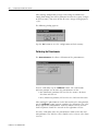
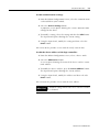
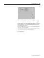
After making configuration changes and exiting the MobileView
Config Tool dialog, you will be prompted to write the registry changes
to Flash memory. You must do this to retain changes through power
cycles.
The following dialog appears.
Tap the Yes button to save the configuration to Flash memory.
Calibrating the Potentiometer
The Potentiometer tab allows calibration of the potentiometer.
To start calibration, tap the Calibrate button. The radio button
indicator prompts you to move the potentiometer to the:
• Min (Minimum) position, full travel in the counter clockwise
direction and then to
• Max (Maximum) position, full travel in the clockwise direction.
After moving the potentiometer to the Min and then the Max position,
tap the Calibrate button again to complete the calibration. The value
to the right of the Potentiometer slide bar should read 127 and the
slide bar pointer should be centered on the rightmost tick line.
To verify calibration, move the potentiometer knob to the Min and
Max positions. The slide bar value should read as a linear value from
0 to 127.
Publication 2727-UM003D-EN-P
Configuring the MobileView Terminal
3-3
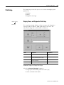
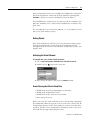
Adjusting Display and Touch Screen Settings
The Display/Touch tab lets you control the brightness and contrast
of the display and calibrate the touch screen.
Display Configuration
To adjust the brightness and contrast, simply move the associated
scroll bars and/or tap buttons.
Screen Saver
To set the screen saver, select Start>Settings>Control Panel and run
Display Settings.
The screen saver will be enabled if there is no keypad, touch screen,
or operator activity for a time period exceeding the Idle Time setting
in the Backlight tab of the Display Settings. The screen saver
backlight brightness can also be set. To turn off the backlight while
on external power, enter a turn-off time of 30 seconds to 30 minutes.
Once in screen saver mode, the first keypad key or touch screen
activation will only deactivate the screen saver but not activate the
buttons or functions assigned to the keypad key or touch screen touch
cells. The handwheel, keyswitch, pushbutton and potentiometer
operators will also deactivate the screen saver but remain fully
functional while screen saver mode is active.
Publication 2727-UM003D-EN-P
3-4
Configuring the MobileView Terminal
Touch Screen Calibration
To calibrate the touch screen, tap the Calibrate Touch button. An
image with a white background, a cross hair target in the center of the
screen, and instructions at the top, will appear. Simply follow the
instructions to complete the calibration. For best results use a stylus.
ATTENTION
!
Do not use a sharp object, such as a screw driver when
operating the touch screen. Using sharp objects may
damage the touch screen.
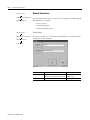
Setting the Handwheel to Zero
The Handwheel tab calibrates the electronic handwheel of the
MobileView terminal.
The handwheel registers a 16-bit value (-32768 to +32768) which can
be processed in the target application as needed and is calibrated for
50 pulses per revolution. Every single increment of the handwheel is
equal to a value of 1.
To calibrate the handwheel:
1. Move the handwheel to the desired start position.
2. Tap the Reset button on the Handwheel tab of the MobileView
Config dialog.
The handwheel slide bar will move to the leftmost tick mark and
the actual value will be reset to a start value of 0.
Publication 2727-UM003D-EN-P
Configuring the MobileView Terminal
3-5
Configure Keypad Settings
You can adjust the keypad auto-repeat rate through the Keyboard
Properties dialog in the Control Panel.
To set the auto-repeat rates:
1. Select Start>Settings>Control Panel.
2. Double-tap Keyboard.
3. Tap the Enable character repeat check box.
4. Select the desired Repeat delay and Repeat rate settings and
then tap OK to save the changes and exit the dialog.
TIP
The Keypad auto-repeat rate settings are for the
physical left and right membrane keypads only. You
cannot configure the on-screen, alphanumeric input
panel.
Publication 2727-UM003D-EN-P
3-6
Configuring the MobileView Terminal
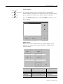
Configuring Startup Settings
The Startup tab determines what occurs after a restart or power cycle
of the MobileView terminal.
You can select the following startup actions for the MobileView terminal:
• Update OS Image on Next Startup - Loads the OS (Operating
System) image from the BOOTP Server via the network the next
time the MobileView is started.
IMPORTANT
The Ethernet connection must have been
established, the BOOTP Server must be
correctly configured, and an OS image file
must be available. See the MobileView
G750/MT750 Flash Update documentation for
more information.
• Disable internal network controller: - Deactivates the internal
Ethernet interface CELAN1:Onboard Ethernet at the next startup.
To enable the network controller after disabling:
a. Deselect “Disable Internal Network Controller”.
b. Perform a registry backup by selecting
Start>Programs>MobileView>Registry Backup.
c. Cycle power to the MobileView terminal.
Publication 2727-UM003D-EN-P
Configuring the MobileView Terminal
3-7
Activating/Testing Pushbutton LEDs
The Pushbuttons tab allows activation of the push button LEDs, that
are present, on the MobileView terminal.
Tap one of the 3 pushbutton targets to switch the corresponding LED
to Flashing, On, or Off. The first tap switches the LED to Flashing, the
second tap switches the LED to On, and the third tap switches the
LED to Off.
IMPORTANT
This activation test utility activates the push button
LEDs only. The push button and keyswitch position
states are not affected.
Loading a New Image File
The Image Update tab allows selection, validation, and loading of a
new WinCE Flash image file to the MobileView terminal.
You can update the image directly from a PC card or using an
Ethernet or Serial connection download the update file to the
MobileView Terminal. Do not remove the PC card until the image
update procedure is complete.
Interruptions may occur when downloading large files over Ethernet
connections using two or more switches.
Publication 2727-UM003D-EN-P
3-8
Configuring the MobileView Terminal
1. Tap the Image Update tab.
2. Tap the Image File button. Browse and select the .bin file, then
tap the Start Update button.
IMPORTANT
If the IPSM is still formatting the flash area, you will
see the message, “PSM is active. Do you want to
deactivate PSM and reset the device?”. Follow the
bulleted procedure. If this message does not appear,
proceed with step 3.
• Tap the OK button to stop the IPSM. The message “PSM
deactivate” appears.
• Tap the OK button to quit and reset the terminal. If the terminal
did not reset, the file SoftReset.exe will not copy to the
terminal’s root directory.
• Select Start>Programs>MobileView>MV Configuration Tool
• Repeat step 1.
3. Tap Yes to continue past two warnings.
Publication 2727-UM003D-EN-P
Configuring the MobileView Terminal
3-9
4. The image update starts.
The Updating Image dialog shows the progress of the update.
Tool Version
ATTENTION
!
After starting an update, do not cycle power or
remove the PC card until the update is
complete. If the update is interrupted, the
terminal will become inactive and can only be
initialized and updated using the BootP server.
See the MobileView G750/MT750 Flash Update
documentation for more information.
Publication 2727-UM003D-EN-P
3-10
Configuring the MobileView Terminal
When the update is complete, the following dialog appears.
5. Tap the OK button to reset the terminal.
A dialog displays the message “erasing PSM, please wait...”.
When this operation is complete, the terminal resets.
6. The update is complete. You can calibrate the touch screen and
safely remove the PC card from the terminal.
Clearing the Registry
IMPORTANT
All modifications made to the registry since product
delivery will be deleted.
To clear the registry and restore factory default settings:
1. Tap the Clear Registry button on the Image Update tab.
A warning dialog appears letting you know that the current
settings will be replaced with the factory default settings and
that the terminal will reset.
2. Tap Yes to continue. The terminal resets.
Publication 2727-UM003D-EN-P
Configuring the MobileView Terminal
Checking the Operating and
Control Elements
3-11
You can verify the operating and control elements of the MobileView
terminal using the System Check software. You can check the
following operating and control elements:
• Override potentiometer (option)
• Electronic handwheel (option)
• Membrane Keypad
• Touch screen
• Display
ATTENTION
!
Any changes to the contrast or brightness
setting in the display backlight system check
will be applied to the MobileView terminal and
the configuration tool.
• Illuminated push button (option)
• Key switch (option)
• IPSM Flash file system
The following safety elements cannot be checked with this utility:
• Emergency stop switch
• Enabling switches
The System Check software also lets you check the MobileView
terminal data, such as the CPU memory, interface module, or
operating elements.
To run this software, select:
Start>Programs>MobileView>System Check
Publication 2727-UM003D-EN-P
3-12
Configuring the MobileView Terminal
Transferring Data with a
Personal Computer
This section shows how to transmit data between the MobileView
terminal and a PC using the MicroSoft ActiveSync software. It shows
how to:
• verify serial port availability
• install the Microsoft ActiveSync software
• connect the MobileView terminal to a PC
• disconnect communications
Verifying Serial Port Availability
To verify that your PC serial port is available:
1. For Windows 95, Windows 98 and Windows NT systems:
On your PC, select Start>Settings>Control Panel.
For Windows 2000 systems:
On your PC, right-click My Computer, select Manage and then
Device Manager.
2. For Windows 95 and Windows 98 systems:
Double-click the System icon and select Device Manager tab.
For Windows NT systems:
Double-click the Ports icon.
For Windows 2000 systems:
Double-click Ports from the menu.
3. View the devices by type or number. Double-click the desired
port.
4. Click the Port Settings tab or the Settings button and set the
Bits Per Second or Baud Rate to match MobileView settings.
Bits per second setting
5. Click OK to apply any changes and close the windows.
Publication 2727-UM003D-EN-P
Configuring the MobileView Terminal
3-13
Installing Microsoft ActiveSync Software
Microsoft ActiveSync enables you to connect the IDA to your PC.
ActiveSync version 3.1 or greater is required. Download ActiveSync
from the Internet at
www.microsoft.com/pocketpc/downloads/activesync.asp and follow
Microsoft’s installation instructions. When the software installation is
complete, continue by following the procedure below.
Connecting the MobileView Terminal to a PC
To connect the MobileView terminal to a PC:
1. Remove the back cover of the MobileView terminal.
2. Plug the MobileView Download Cable (Catalog Number
2727-MRC1) into the RS-232 Port (note the location of pin 1). See
page 2-12.
3. If ActiveSync or the Get Connected window is not open already
on the PC, follow these steps:
• Select Start>Programs>Communications>ActiveSync>OK
on the PC. The ActiveSync window opens.
• In the ActiveSync window, select File, Get Connected from
the menu bar. The Get Connected window will open.
4. In the Get Connected window, click the Next button.
5. On the MobileView Terminal, select
Start>Programs>Communication>ActiveSync. MobileView
Terminal opens a connection status box On the PC, the Get
Connected window instructs you to wait while Setup locates
your mobile device. When the PC and MobileView connect, the
MobileView connection status box closes. The PC’s ActiveSync
window shows “Connected” and a New Partnership window will
open.
6. In the New Partnership window on the PC, click No in response
to the question “Would you like to set up a partnership?” Then,
click the Next button.
Publication 2727-UM003D-EN-P
3-14
Configuring the MobileView Terminal
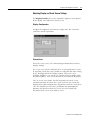
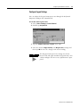
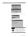
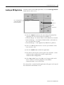
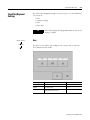
7. The New Partnership window closes and the ActiveSync
window shows you are connected as “Guest”.
Connection Status Box on the PC
Menu bar
Device identity
Status
Connection Status Box on the MobileView Terminal
Status
8. Once you are connected, you can use Windows Explorer to
transfer files between your PC directories and your Mobile
Device directories.
TIP
If the connection fails, try it again, making sure you
follow steps 3 and 4 in close sequence. If the
connection still fails, use the ActiveSync
Troubleshooter, which provides diagnostic steps to
identify and correct problems. On the ActiveSync
Help menu, tap Microsoft ActiveSync Help.
Double-click the ActiveSync Troubleshooter book,
then double-click ActiveSync Troubleshooter.
If communication problems occur:
• restart the ActiveSync software on the PC.
• reduce the baud rate on the MobileView terminal by selecting
Start>Settings>Network and Dial-up Connections and then
select the com1_115K connection. Then select File>Properties.
Select the configure tab and then select the desired baud rate
from the Baud Rate pull-down menu.
Publication 2727-UM003D-EN-P
Configuring the MobileView Terminal
3-15
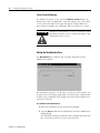
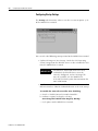
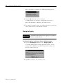
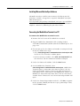
Disconnecting Communication
To disconnect communication between the MobileView and PC:
1. If the connection status box is minimized on the MobileView,
double-tap the Connection icon
at the bottom of the
MobileView terminal screen to open it.
Disconnect button
2. Tap the Disconnect button. Communication disconnects and
the connection status box closes.
3. The ActiveSync window on the PC will show a status of “Not
Connected”. This may take some time before it is displayed.
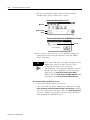
Installing Programs
You can install programs using the ActiveSync software on a PC
(covered in the previous section) or a PC card.
• For PC program transfers, use Windows Explorer on the PC.
The MobileView terminal will appear as a MobileView device
directory.
• For PC card transfers, insert the PC card in the PC card slot of
the MobileView terminal and use Windows Explorer on the
MobileView terminal. The PC card image will appear as “Storage
Card” directory under the root directory.
IMPORTANT
The “Flash Storage” directory is the only directory
stored in flash. Programs and data installed in other
directories are lost when power is cycled to the
MobileView terminal. Save all data you want to
retain in the “Flash Storage” directory.
IMPORTANT
Many programs store their drivers in the Windows
directory, but this directory is not saved. These
programs will not function after you turn off the
MobileView terminal. Relocate drivers to the “Flash
Storage” directory.
Publication 2727-UM003D-EN-P
3-16
Configuring the MobileView Terminal
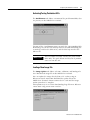
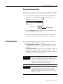
Saving Registry Settings
ATTENTION
!
Any hardware configuration or Ethernet network
configuration changes must be saved using the
Registry Backup or they will be lost during a
MobileView terminal power cycle.
To save the current registry settings:
1. Tap the Start button and select
Programs>MobileView>Registry Backup.
To save the registry, tap the OK button. Saving the registry may take
15 seconds. The registry backup will automatically close.
Publication 2727-UM003D-EN-P
Chapter
4
Using RSView ME Station
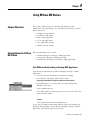
Chapter Objectives
This chapter shows how to use RSView ME Station on your
MobileView 2727-M7P20D1Q2, or -M7P20D1Q3 terminal. It includes
topics on how to:
• configure startup options
• start RSView ME Station
• load an ME application
• run an ME application
• view application settings
• modify terminal settings
Startup Options for RSView
ME Station
RSView ME Station can be started:
• without loading or running an .MER application
• automatically loading an .MER application
• automatically loading and running an .MER application
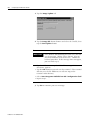
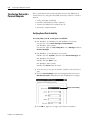
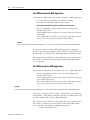
Start RSView without Loading or Running .MER Application
To start RSView ME Runtime without loading or running an .MER
application:
• select the RSView ME Station icon from the desktop
• select RSView ME Station from the Start menu
Programs>Rockwell Software>RSView ME Station
• type MERuntime.exe and its path in the Run dialog of the
Windows Start menu.
Path to MERuntime.exe
If the path to RSView ME contains spaces, you must enclose the
path in double quotes.
Example:
"Flash Storage\Rockwell Software\RSViewME\MERuntime.exe"
If you copy the RSView ME Station shortcut from the desktop to the
Windows Startup folder (\Flash Storage\Windows\Startup), RSView
ME station will automatically run on startup.
1
Publication 2727-UM003D-EN-P
4-2
Using RSView ME Station
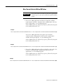
Start RSView and Load .MER Application
To start RSView ME Station and automatically load an .MER application:
• select the RSView ME Station icon from the desktop
• select RSView ME Station from the Start menu:
Programs>Rockwell Software>RSView ME Station
• type the appropriate shortcut path in the Run dialog on the
Windows Start menu.
Path to MERuntime.exe, followed by a space, followed by the path
to the .MER
If the path to RSView ME or the path to the application contains
spaces, you must enclose the path in double quotes.
Example:
"Flash Storage\Rockwell Software\RSViewME\MERuntime.exe" "Flash Storage\Rockwell Software\RSViewME\Runtime\MYAPP.MER"
If you place a shortcut to the .MER application into the Windows
Startup (\Flash Storage\Windows\Startup) folder, the ME Runtime will
automatically start and load the .MER application on terminal startup.
If the application specified in the Run dialog or the Startup folder does
not exist or is corrupted, the main RSView ME Configuration Mode
screen will open.
Start RSView and Run .MER Application
To start RSView ME Station and automatically run an .MER application:
• type the appropriate shortcut path in the Run dialog on the
Windows Start menu.
Path to MERuntime.exe, followed by a space, followed by the path
to the .MER, followed by /r
If the path to RSView ME or the path to the application contains
spaces, you must enclose the path in double quotes.
Example:
"Flash Storage\Rockwell Software\RSViewME\MERuntime.exe" "Flash Storage\Rockwell Software\RSViewME\Runtime\MYAPP.MER" /r
If you place a shortcut with the above command line in the Windows
Startup folder (\Flash Storage\Windows\Startup), the ME Runtime will
start and automatically run the .MER application.
If the application specified in the Run dialog or the Startup folder does
not exist or is corrupted, the main RSView ME Configuration Mode
screen will open and display the following message:
Unable to load application
Publication 2727-UM003D-EN-P
Using RSView ME Station
4-3
Other Shortcut Paths for RSView ME Station
IMPORTANT
If the path to RSView ME or the path to the application
contains spaces, you must enclose the path in double
quotes.
• To run the .MER application and delete its log files without
replacing the terminal’s communication configuration with that
of the applications, use the following path:
Path to MERuntime.exe, followed by a space, followed by the path
to the .MER, followed by /r/d
Example:
"Flash Storage\Rockwell Software\RSViewME\MERuntime.exe" "Flash Storage\Rockwell Software\RSViewME\Runtime\MYAPP.MER" /r/d
To run the .MER application and replace the terminal’s
communication configuration with that of the applications
without deleting its log files, use the following path:
Path to MERuntime.exe, followed by a space, followed by the path
to the .MER, followed by /r/o
Example:
"Flash Storage\Rockwell Software\RSViewME\MERuntime.exe" "Flash Storage\Rockwell Software\RSViewME\Runtime\MYAPP.MER" /r/o
• To run the .MER application, delete its log files, and replace the
terminal’s communication configuration with that of the
applications, use the following path:
Path to MERuntime.exe, followed by a space, followed by the path
to the .MER, followed by /r/d/o
Example:
"Flash Storage\Rockwell Software\RSViewME\MERuntime.exe" "Flash Storage\Rockwell Software\RSViewME\Runtime\MYAPP.MER" /r/d/o
Publication 2727-UM003D-EN-P
4-4
Using RSView ME Station
Starting RSView ME from
the desktop
If RSView ME Station does not automatically run on startup, you can
access it from the Windows Start menu or the desktop icon.
To start RSView ME Station:
• select RSView ME Station from the Windows Start menu.
Start>Programs>Rockwell Software>RSView ME Station
• select the RSView ME Station icon on the desktop.
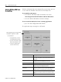
To access RSView ME Station from a running application:
• press the Goto Configuration Mode button.
The application stops running but is still loaded.
Name of application that is currently loaded.
Only appears if application is loaded.
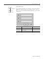
To activate buttons:
• on keypad terminals, select the
corresponding function key [Fx]
• on touch screen terminals, tap the
button with your finger or stylus.
• if a mouse is attached, make
selections with the mouse.
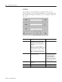
Publication 2727-UM003D-EN-P
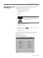
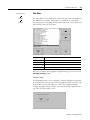
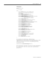
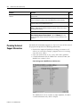
Main Screen Button
Description
Load Application (F1)
Opens another screen where you select an application to load.
Once loaded, the application name will appear under Current
Application.
Run Application (F2)
Runs the .MER application displayed under Current Application.
An application must be loaded before you can run it.
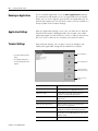
Application Settings (F3)
Opens a menu of application-specific configuration settings.
Terminal Settings (F4)
Opens a menu of options to configure non-application, specific
terminal settings for the MobileView terminal.
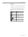
Delete Log Files Before
Running (F5)
Toggles between Yes and No. If you select Yes, all data log files,
alarm history and alarm status files will be deleted before the
application runs. If you select No, log files are not deleted.
Reset (F7)
Resets the terminal. The action that occurs on startup depends
on whether shortcut paths are defined in the Windows Startup
folder.
Exit (F8)
Exits RSView ME Station.
Using RSView ME Station
4-5
Screen Buttons
RSView ME Station uses screen buttons for data entry and navigation.
• To use the touch screen, tap the button with your finger or
stylus.
• To use the keypad, select the function key listed on the button,
or in some cases, the corresponding key on the keypad.
Besides operation specific buttons which are used to modify
configuration data, most screens have a combination of the following
buttons.
Screen Buttons
Close
[F10]
OK
[F7]
Cancel
[F8]
Description
Returns to the previous screen.
Accepts modified values and returns to
previous screen.
Cancels the current operation without
saving any changes.
Moves highlight up or down a list.
Selects a highlighted screen or item from a
list.
Publication 2727-UM003D-EN-P
4-6
Using RSView ME Station
Input Panel
Many screens have buttons that access fields where you must
enter/edit data. When you press the button or function key, the Input
Panel opens ready for you to input data.
If the field is restricted to a numeric value, only the 0-9 keys will be
enabled. If the value is an IP address, the 0-9 and decimal point keys
will be enabled. All other keys will be disabled.
Display Area
Character Keyboard
• On a touch terminal, tap the keys.
• On a keypad terminal, use the
arrow keys on the keypad to
select keys.
• If a mouse is attached, use the
mouse to select keys.
Controls
Controls
Function
SHF
Switches keys between their shifted and unshifted state. The initial default is shifted.
CAPS
Switches keys between lowercase and uppercase characters. The initial default is lowercase.
SPACE
Enters a space between characters in the Display Area.
Backspace
Deletes the previous character (to the left of the cursor) in the Display Area.
Select
Selects a character and enters it in the Display Area.
→←↑↓
Selects the character to the right, left, above or below the currently selected character.
Enter
Accepts the entered characters and returns to the previous screen
ESC
Cancels the current operation and returns to the previous screen.
To enter characters in the Display Area:
1. Select a character on the Character Keyboard.
2. Press the Select button to copy the character to the Display
Area.
3. When done entering all characters, press Enter. You will return
to the previous screen.
You will return to the previous screen with the newly entered data.
Publication 2727-UM003D-EN-P
Using RSView ME Station
Loading an ME Application
4-7
To load an RSView ME .MER application, select the Load Application
button on the main screen:
List of .mer applications
stored in the compact
flash of the terminal.
Moves
highlight up
Moves
highlight down
1. Select the Source button to select the storage location of the
application file you want to load. The options are:
• Internal Storage - the Internal Flash in the MobileView terminal.
• External Storage 1 - the External PCMCIA Flash card loaded in
the card slot of the terminal.
• External Storage 2 - not supported by MobileView products.
2. Select an .MER file from the list. Use the up and down cursor
keys to select a file.
3. Select the Load button to load the application.
4. You will be asked if you want to replace the terminals’ current
communication configuration with the application’s
communication configuration.
5. Select Yes or No. If you select Yes, any changes made to the
device addresses or driver properties in the RSLinx
Communications screen will be lost.
The name of the currently loaded application will appear at the top of
the main RSView ME Station screen.
Publication 2727-UM003D-EN-P
4-8
Using RSView ME Station
Running an Application
To run a loaded application, select the Run Application button on
the main RSView ME Station screen. An application must be loaded,
before you can run it. Log files generated by the application may be
deleted if this option was selected on the main screen or enabled as a
Startup Option under Terminal Settings.
Application Settings
From the Application Settings screen, you can show device shortcuts
defined for the loaded .MER application. For example, your .MER
application might have SLC defined as a device shortcut name for the
SLC 5/05. Device shortcuts are read-only and cannot be edited.
Terminal Settings
From Terminal Settings, you can open screens to configure and
modify non-application settings for the MobileView terminal.
• On a touch terminal, tap the
button.
Moves highlight up
Networks and Communications
• On a keypad terminal, press
the corresponding key on the
keypad
Moves highlight down
Selects highlighted
item and opens screen
Returns to previous
screen.
Publication 2727-UM003D-EN-P
Terminal Setting
Description
About RSView ME Station
Describes the RSView ME Station software installed on
the 2727-M7P20D1Q2, 2727-M7P20D1Q3 terminals.
Diagnostics Setup
Forwards diagnostic messages form a remote log
destination to a computer running diagnostics.
File Management
Copies or deletes application files or font files from a
storage location.
Font Linking
Links a font file to a base font loaded on the terminal.
Networks and Communications
Configures network connections and communication
settings specific to the application.
Print Setup
Configures settings for printing displays, alarm messages,
and diagnostics messages generated by the application.
RSView ME Station Startup
Specifies whether the terminal starts up in configure or
run mode. Also lets you enable/disable tests to run on the
terminal at startup.
Time/Date
Sets the date, time.
Using RSView ME Station
Networks and
Communications
Terminal Settings
Networks and Communications
KEPServer Port ID’s
4-9
From the Networks and Communications screen, you can access
settings for:
• KEPServer Port ID’s
• Network Connections
• RSLinx Enterprise Communications
KEPServer Port ID’s
To access the KEPServer Port ID’s screen, you must have KEPServer
Enterprise installed on your terminal. Otherwise, you will get an error
message when accessing this screen.
Publication 2727-UM003D-EN-P
4-10
Using RSView ME Station
Terminal Settings
Networks and Communications
RSLinx Enterprise Communications
RSLinx Enterprise Communications
The RSLinx Enterprise Communications screen shows a treeview of
installed communication cards and network configurations. You can:
• edit/view the driver settings for the communication protocol
used by your .MER application.
• edit the device address of the controller on the network.
The procedure for editing these settings is the same regardless of the
communication protocol. The only differences are the properties for
each communication protocol and the device address of the logic
controller. The properties for each communication protocol are
defined immediately after this section.
Ethernet Driver
Has no properties to edit.
Communication Driver
Publication 2727-UM003D-EN-P
AB_ETH-1
<No Devices>
Serial-DF-1
<No Devices>
Using RSView ME Station
4-11
To edit communication settings:
1. From the RSLinx Configuration Screen, select the communication
card installed on your terminal.
2. Select the Driver Settings button.
A properties screen opens showing the current communication
settings for the driver.
3. To modify a setting, select the setting and then the Edit button.
The Input Panel opens showing the current setting.
4. Using the Input Panel, modify the setting and then select the
Enter button.
You return to the previous screen with the newly entered data.
To edit the device address of the logic controller:
1. From the RSLinx Configuration screen, select a device node.
2. Select the Edit Device button.
A screen opens showing the name of the device and its current
node address.
3. To modify the device address, press the Device Address button.
The Input Panel opens showing the current address.
4. Using the Input Panel, modify the address and then select the
Enter button.
You return to the previous screen with the new address.
IMPORTANT
Modified settings do not take effect until the terminal
is rebooted.
Publication 2727-UM003D-EN-P
4-12
Using RSView ME Station
Terminal Settings
Network Connections
Networks and Communications
Network Connections
The Network Connections screen lets you configure the following for
the MobileView terminal:
• Device Name
• Network Adapters
• Network Identification
Terminal Settings
Device Name
Networks and Communications
The Device Name screen identifies the MobileView terminal to other
computers on the network.
Network Connections
Device Name
Publication 2727-UM003D-EN-P
Field
Description
Valid Values
Device Name
Name that identifies the MobileView
terminal to other computers on the network.
15 characters maximum,
without spaces
Device Description
Provides a description of the terminal.
50 characters maximum
Using RSView ME Station
Terminal Settings
Networks and Communications
Network Connections
Network Adapters
4-13
Network Adapters
The Network Adapters screen configures driver settings for all
network adapters installed on the terminal. The only network adapter
on the MobileView terminal is the Built-in Ethernet Controller.
Press the Name Servers button and/or IP Address button to access
driver settings.
Name Servers
Defines Name Server addresses for the Network Adapter. These
addresses are automatically assigned if DHCP is enabled for the
network adapter.
Field
Description
Valid Values
Primary DNS
The address of the primary DNS resolver.
xxx.xxx.xxx.xxx
Secondary DNS
The address of the secondary DNS resolver.
xxx.xxx.xxx.xxx
Primary WINS
The address of the primary WINS resolver.
xxx.xxx.xxx.xxx
Secondary WINS
The address of the secondary WINS resolver. xxx.xxx.xxx.xxx
Publication 2727-UM003D-EN-P
4-14
Using RSView ME Station
IP Address
The IP Address screen identifies the IP address of the selected
network adapter. If the network the MobileView is connected to does
not automatically assign an IP address, you can assign the address in
this screen.
Field
Description
Valid Values
Use DHCP
Enables or disables DHCP (Dynamic Host
Configuration Protocol) settings. DHCP
automatically allocates network devices and
configurations to newly attached devices on
the network.
Yes (default)
No
If DHCP is set to Yes, the MobileView is
automatically assigned an IP address, Subnet
Mask and Gateway. The fields are disabled.
If DHCP is set to No, you can enter the IP
address, Subnet Mask and Gateway address.
IP Address
A unique address identifying the MobileView
on the Ethernet network.
xxx.xxx.xxx.xxx
000.000.000.000 (default)
Range of values for the first
set of decimal numbers is
1-255 unless all fields are set
to 000. The range of values for
the last three sets of decimal
numbers is 0-255.
Publication 2727-UM003D-EN-P
Subnet Mask
Address must be identical to the server
subnet mask.
xxx.xxx.xxx.xxx
Gateway
Optional Gateway address
xxx.xxx.xxx.xxx
Mac ID
Read only field
Using RSView ME Station
Terminal Settings
Networks and Communications
Network Connections
Network Identification
4-15
Network Identification
The Network Identification screen configures settings that enable the
MobileView terminal to gain access to network resources. You can
enter a user name, password and domain (provided by your network
administrator).
Field
Description
Valid Values
User Name
Identifies the user to the network.
70 characters maximum
Password
Characters that gain access to network along
with the user name.
No character limitation
Domain Name
Provided by network administrator.
15 characters maximum
Publication 2727-UM003D-EN-P
4-16
Using RSView ME Station
Diagnostic Setup
The Diagnostic Setup screen configures diagnostics for the current
computer. The screen shows a treeview of possible diagnostic nodes.
Terminal Settings
To access the Remote
Log Setup or Message
Routing, select the node
and then the Edit button.
Diagnostic Setup
The Remote Log Destination forwards messages that it receives to a
Windows 2000/XP computer running diagnostics. The location is
determined by the IP address and port number.
Field
Description
Valid Values
Address
Address of the remote Windows 2000/XP
computer.
xxx.xxx.xxx.xxx
Port
The port used to communicate with the
remote Windows 2000/XP computer.
4445 (default)
Message Routing
The Message Routing screen lets you access the following screens:
• Remote Log
• RSView Diagnostics List
Each of the above screens shows a list of messages that can be sent to
that destination. The list shows the On/Off status of each message
type. Use the On/Off button to turn a message type on or off. A
message type is enabled if it has a checked box.
Publication 2727-UM003D-EN-P
Using RSView ME Station
File Management
Terminal Settings
File Management
Delete Files
4-17
The File Management screen lets you access screens to:
• Delete Files
• Copy Files
Delete Files
From the Delete Files screen you can select options to:
• Delete Applications - deletes an .MER application file from a
storage location.
• Delete Fonts - deletes a font file from a storage location.
• Delete Log Files - deletes any data log files, alarm history files
and alarm status files in the System Default location on the
MobileView terminal.
Delete Application or Font Files
The process for deleting an application file or a font file is the same.
1. Select the Source button to select the storage location of the
application or font file you want to delete.
• Internal Storage - the Internal Flash in the MobileView terminal.
• External Storage 1 - the External PCMCIA Flash card loaded in
the card slot of the terminal.
• External Storage 2 - not supported by MobileView products.
2. Select a file from the list.
3. Select the Delete button.
4. You will be asked if you want to delete the selected application
or font file from the storage location. Select Yes or No.
Publication 2727-UM003D-EN-P
4-18
Using RSView ME Station
Delete Log Files
Select this option to delete any data log files, alarm history files and
alarm status files in the System Default location on the MobileView
terminal. You will be asked to confirm the operation.
Do you want to delete all of the RSView ME Station Log Files?
Select Yes or No. Any log files not located in the System Default
location will not be deleted.
Terminal Settings
Copy Files
File Management
From the Copy Files screen, you can select options to:
• Copy Applications - copies an .MER application file from one
storage location to another
• Copy Fonts - copies a font file from one storage location to
another.
Copy Files
Copy Applications or Fonts
The process for copying an application file or a font file is the same.
List of files stored
in Internal Flash of
terminal.
1. Select the Source button to select the location of the application
or font file you want to copy.
• Internal Storage - the Internal Flash in the MobileView terminal.
• External Storage 1 - the External PCMCIA Flash card loaded in
the card slot of the terminal.
2. Select the Destination button on the same screen to open the
following screen.
Publication 2727-UM003D-EN-P
Using RSView ME Station
4-19
3. Select the Destination button to select the storage location
where you want to copy the application or font file to. The
destination cannot be the same as the source location.
• Internal Storage - the Internal Flash in the MobileView terminal.
• External Storage 1 - the External PCMCIA Flash card loaded in
the card slot of the terminal.
4. Select the Copy button to copy the selected application or font
file to the selected destination.
If the file exists, you will receive a warning and will be asked if
you want to overwrite the existing application.
5. Select Yes or No.
Publication 2727-UM003D-EN-P
4-20
Using RSView ME Station
Font Linking
Font linking allows you to run a translated application on the terminal
by linking a font file to the base font (for example, linking a Chinese
font file to the base font Arial).
Terminal Settings
Font Linking
For more details on pre-installed terminal fonts and additional fonts
available for downloading, see Appendix B.
Select Base Font
Arial
Courier New
Tahoma
Times New Roman
List of fonts loaded on
the terminal.
Show Links
[F1]
Shows all fonts loaded on the terminal except the
base font. Select the name of the font you are
linking to the base font. Click the Add Fonts button
to link the font file for the selected font to the base
font. You will return to the Linked Fonts screen.
Close
[F8]
Linked Font
Add Linked Font
Courier New
MS Mincho
Tahoma
Times New Roman
Add Fonts
[F1]
Close
[F8]
Base font = Arial
Link:
MS Mincho
External storage 1\MSMINCHO.TTC
Delete Link
[F1]
Deletes linked
font file (if any)
Publication 2727-UM003D-EN-P
Shows the location and name of the
font that is linked to the base font
used by the terminal. If a file is not
linked, box will be empty.
Edit Link
[F2]
Close
[F8]
Edits the link by allowing you to add the
linked file to a font loaded on the terminal.
Using RSView ME Station
Print Setup
Terminal Settings
Print Setup
4-21
The Print Setup screen lets you access screens to configure print
options for:
• Displays
• Alarms
• Diagnostic messages.
Display, Alarm, and Diagnostic Print Setup
The setup for printing displays, alarm messages and diagnostics
messages from an RSView .MER application is the same. The
Advanced Settings for each function are different.
Field
Description
Valid Values
PCL Printer
Type of printer to use.
Laser (default)
Inkjet
Port
Port to use for printing displays, alarm
messages, and diagnostic messages.
Network (default)
Network Path
Network path of printer to use if the Port
selection is Network.
519 characters maximum
Advanced Settings
Press this button to open additional settings.
Advanced Settings for Display Print Setup
Select the Advanced Settings button to:
• change print orientation (portrait or landscape)
• enable or disable draft mode
Publication 2727-UM003D-EN-P
4-22
Using RSView ME Station
Advanced Settings for Diagnostic Messages and Alarm Messages
The following screen configures when to print diagnostic or alarm
messages that are sent to the Network or port.
To configure how messages are queued for printing, select the Print
Messages After button and set one of the following options:
• Specified number of messages
Prints messages after 60 are queued or another specified value.
The default is 60 (about one full page of messages.)
• 500 messages or timeout period, whichever is first
Prints after 500 messages are queued or a specific time period
has elapsed, whichever comes first. The default time period is
168 hours (7 days). You can specify another value. For example,
if 350 messages are in the queue and 7 days have elapsed, the
350 messages will print.
• Specified number of messages or timeout period,
whichever is first
Prints after a specified number of messages are queued or a
specific time period has elapsed, whichever comes first.
The default number of messages to queue is 60. The default
timeout period is 168 hours (7 days). You can change both
values. For example, the number of messages is set to 75 and
the timeout period is set to 48 hours (2 day). If the queue has 75
messages after only 24 hours, these messages will print. If there
are only 15 messages in the queue at 48 hours, the 15 messages
will not print until the time period has elapsed.
Publication 2727-UM003D-EN-P
Using RSView ME Station
Startup Options
Terminal Settings
4-23
The Startup Options screen accesses the following screens to modify:
• RSView ME Station Startup
• Startup Tests
RSView ME Station Startup
RSView ME Station Startup
The RSView Machine Station Startup screen specifies what action the
MobileView terminal takes on startup:
• Do not start RSView ME Station
• Go to Configure Mode of RSView ME
• Run the Current Application
This option is available only if an application is loaded.
RSView ME Station will start up based on shortcuts in the Windows
Startup folder and whether an application is loaded.
Select the On Startup button to switch between Do not start RSView
ME, Go to Configure Mode, or Run the Current Application. Select the
button under the last two options to configure specific settings for
each mode.
Publication 2727-UM003D-EN-P
4-24
Using RSView ME Station
Configuration Mode
The Configuration Mode Options screen specifies whether the
MobileView will boot up in Configure Mode:
• with the current application loaded.
• with the communication configuration of the current application
or the terminal’s RSLinx communication configuration.
If you select Yes to replace the terminal’s communication
configuration with that of the application, any changes made to
the device addresses or driver properties in the RSLinx
Communications screen will be lost.
These options are available only if an application is loaded in the
terminal. If an application is not loaded, both options are disabled and
set to No.
Run Options
Configuration Mode
Run Options
The Run Options screen specifies whether or not:
• to replace the terminal’s communication (RSLinx) settings with
application settings when the application is run.
If you select Yes, any changes to the device addresses or driver
properties in the RSLinx Communications screen will be lost
when the terminal boots up.
• to delete log files (data, alarm history, alarm status) generated by
the terminal from the System Default location before running the
application.
Publication 2727-UM003D-EN-P
Using RSView ME Station
Time/Date/Regional
Settings
The Time/Date/Regional Settings screen lets you access the following
screens to set:
• date
• regional settings
• time
• time zone
TIP
Terminal Settings
Time/Date
Date
4-25
Time/Date/Regional Setting information is not saved
during a reboot.
Date
The Date screen shows and configures the current date in separate
Year, Month and Day fields.
Field
Description
Valid Values
Year
The current year in a 4-digit format.
1980 - 2099
Month
The current month.
1 - 12
Day
The current day. The day of the month is
validated based on the month.
0 - 31
Publication 2727-UM003D-EN-P
4-26
Using RSView ME Station
Terminal Settings
Time/Date
Time
Publication 2727-UM003D-EN-P
Time
The Time screen shows and configures the current time in 24-hour
format in separate Hour, Minute and Second fields.
Field
Description
Valid Values
Hour
The current hour in 24-hour format.
0 - 23
Minute
The current minute in 24-hour format.
0 - 59
Seconds
The current second in 24-hour format.
0 - 59
Using RSView ME Station
Terminal Settings
Time/Date
Time Zone
4-27
Time Zone
The Time Zone screen shows the current time zone that is installed on
the MobileView terminal. Time zones are installed as a part of the
operating system. Changing the time zone adjusts the current time and
date to match the new time zone.
Language
Default Time Zone
English
(GMT -05:00) Eastern Time (US & Canada)
French
(GMT +01:00) Brussels, Copenhagen, Madrid, Paris
German
(GMT +01:00) Amsterdam, Berlin, Bern, Rome, Stockholm, Vienna
Japanese
(GMT +09:00) Osaka, Sapporo, Tokyo
If the selected time zone supports Daylight Savings, you can select the
Daylight Savings button.
Daylight Savings
The Daylight Savings screen configures whether daylight savings time
is in effect for the current time zone. Daylight Savings is set to Yes for
all time zones except for Japanese, which does support daylight
savings. Daylight savings changes are not permanently applied until
you close the Time Zone screen.
Publication 2727-UM003D-EN-P
4-28
Using RSView ME Station
Publication 2727-UM003D-EN-P
Chapter
5
CE Thin Client Operating Instructions
Chapter Objectives
This chapter provides instructions on how to:
• start up or power on the MobileView terminal
• set up an auto start sequence
• configure Ethernet network settings
• save registry settings
• start terminal services
• shut down or power off the MobileView terminal
• reset the time and date
Starting Up/Powering On
the Terminal
To start up or power on the MobileView terminal:
1. Attach the MobileView Connection Cable to the Junction Box
Cable as shown on page 2-4. Tighten threaded coupling until it
is finger tight.
2. Check the MobileView terminal for a start-up screen.
If the start-up screen does not appear, check the 24V dc power
source and cable connections at the Junction Box and
MobileView terminal.
1
Publication 2727-UM003D-EN-P
5-2
CE Thin Client Operating Instructions
Setting Auto Start
To configure the Auto Start sequence, copy the Remote Desktop
Connection shortcut from the desktop to the Windows Startup folder
(storage card\windows\startup).
Configuring Ethernet
Network Settings
To configure the onboard Ethernet communications hardware
of your MobileView terminal:
1. Tap the Start button and select Settings>Control Panel.
2. Double-tap the Network and Dial-up Connections icon.
3. Double-tap the CELAN1 icon.
Publication 2727-UM003D-EN-P
CE Thin Client Operating Instructions
5-3
4. Tap the IP Address tab and select either Obtain an IP Address
via DHCP or Specify an IP Address, depending on your
network configuration.
If you select Specify an IP Address, complete the 3 text boxes
with information from your network administrator or ISP. Use
the on-screen input panel to enter the text. You can access the
input panel by tapping the Stylus icon on the task bar.
IP Address must be a
unique address on the
LAN.
Subnet Mask must be
identical to the server
subnet mask.
Default Gateway is
optional.
5. Tap OK in the settings dialog. A notification window appears
prompting you to either remove and reinstall your card or restart
the device for the new settings to take effect. Tap the OK button
in notification window.
6. Tap OK on the Network Configuration dialog and close the
Control Panel.
Saving Registry Settings
ATTENTION
!
Any hardware configuration or Ethernet network
configuration changes must be saved using the
Registry Backup or they will be lost during a
MobileView terminal power cycle.
To save the current registry settings:
1. Tap the Start button and select
Programs>MobileView>Registry Backup.
2. To save the registry, tap the OK button. Saving the registry may
take 15 seconds. The registry backup will automatically close.
Publication 2727-UM003D-EN-P
5-4
CE Thin Client Operating Instructions
Starting Terminal Services
To connect to a terminal server as a CE client:
TIP
Before connecting to the server as a client, move the
server task bar to the top of the screen. This will
make it easier to access the client and CE task bars,
and size the application screens for optimal viewing
on the MobileView terminal.
1. Double-tap the Remote Desktop Connection shortcut on the
desktop of the MobileView terminal or select the Terminal
Server Client application from the Programs>Remote Desktop
Connection on the Start menu.
2. Enter the Terminal Server’s Name or a valid TCP/IP address in
the Server box using the on-screen input panel or select a
server name or address from the Recent Servers box.
3. Tap the Connect button. A server log on window similar to the
one below appears.
4. Enter your user name and password to operate as an active CE
client.
Publication 2727-UM003D-EN-P
CE Thin Client Operating Instructions
Shutting Down/Powering
Off the Terminal
5-5
To shut down or power off the terminal:
1. Close down all applications that are running on CE client.
2. Tap the Start button on the CE client task bar. Select Shutdown
and then Log Off to disconnect from the terminal server.
3. Remove 24V dc power from the MobileView junction box or
disconnect the MobileView connection cable from the junction
box cable.
IMPORTANT
Setting the Date and Time
The “Flash Storage” directory is the only directory
stored in flash. Programs and data installed in other
directories are lost when power is cycled to the
MobileView terminal. Save all data you want to
retain in the “Flash Storage” directory.
The real-time clock in the MobileView terminal is not backed up by a
battery. You must reset the date and time and after every power cycle.
Set the date and time by selecting Start>Settings>Control
Panel>Date/Time.
Publication 2727-UM003D-EN-P
5-6
CE Thin Client Operating Instructions
Publication 2727-UM003D-EN-P
Chapter
6
Windows CE Applications
Chapter Objectives
This chapter covers:
• MobileView software
• generating programs for Windows CE
• virtual channel
MobileView Software
The MobileView terminal is delivered with pre-installed software that
is stored in the flash of the device. This image contains the Windows
CE operating system core and additional applications.
Operating system:
Windows CE 3.0 for 2727-M7P20D1P1
Windows CE 4.1 for 2727-M7P20D1Q2, 2727-M7P20D1Q3
• Shell
• System Control
• Net Web Explorer
• ActiveSync
Pre-installed application programs:
• MS Terminal Server Client V1.5
• Pocket Registry Editor
• Pocket Paint V3.0
• Pocket Notepad V2.1.1
Pre-installed drivers:
• PC card wireless LAN card type Orinoco PC Card Silver 11Mbit/s
IEEE 802.11b
• PC card for Windows CE standard modem
• IrDA/serial keypad interface for PS-2 keypad for KeyMate by
MicroFoundry.
MobileView-specific software:
• Toggle-Sip (Software-Keypad)
• VirtualChannel VC
• MobileView Configuration Tool for configuration of operating
and control elements, display, touch screen and registry backup.
1
Publication 2727-UM003D-EN-P
6-2
Windows CE Applications
Generating Programs for
Windows CE
You can easily generate programs for Windows CE. Programming is
similar to an application for a standard MS Windows NT PC. Under
Windows CE, only the number of available WIN32-Apes is limited.
Two software development kits are included on the product CD;
Virtual Channel SDK and CE 4.X SDK. Reference the CD for the CE
4.X SDK User Manual.
Virtual Channel
The protocol “Virtual Channel” (VC) is used to transmit control and
operating element data between a controller (control application
running on a server) and one or more MobileView terminals.
The following data can be transmitted via the VC:
Data
Direction
Value Range
Server <--> MT
Size
(Bytes)
Transmission
Potentiometer
<--
0 to 127
1
Event in case of modification and
upon request of the control
Electrical handwheel
<-->
-32768 to +32768
2
Event in case of modification, upon
request of the control, and as set
command for adjusting
Enable Switch*
<--
0/1
1
Event in case of modification
<-->
On
Flashing
Off
2
As command from the control and as
request from the client to the control.
Contrast, Brightness
<-->
0 to 255
2
As command from the control and as
request from the client to the control.
Time for Screen Saver
<-->
0 to 255
1
As command from the control and as
a request from the client to the
control.
State of Screen Saver
<-->
0 to 1
1
Event or as request from the client to
the control.
Volume
<-->
0 to 255
1
As command from the control and as
request from the client to the control.
Background Lighting
<-->
0 to 1
1
As command from the control and as
request from the client to the control.
Write To Flash
-->
-
-
Command
Pleasant
-->
0 to 255
1
Command
Keep Alive
<--
0 to 65535
-
Command
Keys/buttons below
display
Push button LEDS
* Available on MobileView Guard G750 Terminals only
Publication 2727-UM003D-EN-P
Windows CE Applications
6-3
Data transmission between the controller and MobileView terminal is
based on the Ethernet connection (TCP/IP protocol, Listening Port
0xCEBA). All devices must be identified by their IP address.
Several MobileView terminals may be connected to one controller, but
only one controller can be connected to a MobileView terminal at any
given time.
The VC protocol is an event-driven protocol, i.e. each station can send
data at any time without request.
Getting Started
Refer to the MobileView MT750/G750 User Document CD that ships
with the terminal for the Virtual Channel Development Kit. The
Development Kit includes the API functions, header files,.all files, and
sample code.
Activating the Virtual Channel
To enable the user of the virtual channel:
1. Select Start>Programs>MobileView>Virtual Channel
2. Double-tap the K icon on the status bar.
3. Enter server IP address and tap the Connect button.
Events Causing the Client to Send Data
•
•
•
•
Modification
Modification
Modification
Data inquiry
of
of
of
of
value of potentiometer (override)
handwheel value
key status of a key/button
server
With each event, the client sends the server a data package containing
the information about the type of event as well as the current data of
all operating elements. If the client produces several events one after
the other, and the server cannot process all of them at once, the server
will send one message containing all events.
Publication 2727-UM003D-EN-P
6-4
Windows CE Applications
Events of Server
By sending a package to the client, the server can set the current
value of the handwheel, or request the current values (position of
handwheel and override potentiometer, as well as state of keys). The
server can also read the current states of the values which can be
modified by the server.
Data Transmission
Client to Server
typedef enum {
eKVCJoystickIsZero
eKVCJoystickNotZero
eKVCSpaceMouseIsZero
eKVCSpaceMouseNotZero
eKVCHandWheelChanged
eKVCOverrideChanged
eKVCKeyPressed
eKVCKeyReleased
eKVCLedValue
eKVCContrast
eKVCBrightness
eKVCVolume
eKVCScreensaverTime
eKVCScreensaverState
eKVCBacklightState
eKVCLed
eKVCJoystickResp
eKVCSpaceMouseResp
eKVCHandWheelResp
eKVCOverrideResp
eKVCAlive
eKVCClientDisconnect
} TKVCEvent;
0x0001
0x0002
0x0004
0x0008
0x0010
0x0020
0x0040
0x0080
0x0100
0x0200
0x0300
0x0400
0x0500
0x0600
0x0700
0x0800
0x0900
0x0A00
0x0B00
0x0C00
0xFE00
0xFF00
typedef struct {
UINT16 event;
struct {
UINT8 overrideVal;
UINT8 keyVal;
TKVCJostickData joystickVal;
SINT16 handWheelVal;
TKVCSpaceMouseData spaceMouseVal;
} data;
} TKVCClientData;
typedef enum {
eKtpKeyboardLedOff = 1,
Publication 2727-UM003D-EN-P
Windows CE Applications
6-5
eKtpKeyboardLedOn = 2,
eKtpKeyboardLedBlink = 3
} TKtpLedState;
typedef struct {
char posX;
char posY;
char posZ;
} TKVCJostickData;
typedef struct {
UINT16 posX;
UINT16 posY;
UINT16 psoZ;
} TKVCSpaceMouseData;
typedef struct {
SINT16 absVal;
SINT16 dynVal;
}TKVCHandWheelData;
Server to Client
typedef enum {
eKVCSetWheelValue,
eKVCSetLed
eKVCSetContrast,
eKVCSetBrightness,
eKVCSetVolume,
eKVCSetScreensaver,
eKVCGetLed,
eKVCGetContrast,
eKVCGetBrightness,
eKVCGetVolume,
eKVCGetScreensaver,
eKVCGetJostickValue,
eKVCGetSpaceMouseValue,
eKVCGetOverrideValue,
eKVCGetWheelValue,
eKVCSwtichBacklight,
eKVCGetBacklightState,
eKVCPlaySound,
eKVCWriteFlash
eKVCDisconnect
} TKVCCommand;
typedef struct {
TKVCCommand command;
SINT16 param;
} TKVCServerData;
Publication 2727-UM003D-EN-P
6-6
Windows CE Applications
Example: Interface on Server
On the server side, the VC protocol is represented by two classes:
CKVCServerand CKVCConnection. An object of the CKVCServer class
represents the actual server (the "listener") and an object of the
CKVCConnection class represents a connection to a client.
"Server class"
class CKVCServer {
public:
virtual CKVCConnection* OnClientConnect(const char *pIpAdr)= 0;
virtual int OnClientDisconnect(CKVCConnection *pConnection,
TDisconInfo info);
};
CKVCConnection* OnClientConnect(SOCKET socket, sockaddr_in &sockAdr);
This method is always called when a terminal establishes a connection
to the control. The parameters socket and sockAdr specify the
connection parameters of the terminal. This function must return a
pointer to an object of the CKVCConnection class. A return value of
0 indicates that the control rejects the logon of the terminal.
int OnClientDisconnect(CKVCConnection *pConnection, TDisconInfo info);
This method will be called if the server cannot reach the client any
more. The cause of the logoff is specified in info.
Publication 2727-UM003D-EN-P
Windows CE Applications
6-7
Connections
class CKVCConnection {
private:
char *pIpAdr;
public:
virtual int Init(CKVCServer *pServer, SOCKET socket,
SOCKADDR_IN &socketAdr,Tpriority threadPriority);
virtual int Exit();
virtual int OnOverrideChange(SINT16 val);
virtual int OnWheelChange(SINT16 wheelAbsVal);
virtual int OnKeyboardEvent(TKVCEvent keyEvent, int keyNum);
virtual int OnSpaceMouseEvent(TKVCEvent event,
TKVCSpaceMouseData *pSMData);
virtual int OnDisconnect(int val);
virtual
virutal
virtual
virtual
int
int
int
int
GetWheelVal(TKVCHandWheelData &hwData);
GetOverrideVal(SINT16 &overrideVal);
GetSpaceMousePos(TKVCSpaceMouseData &smData);
GetLedState(UINT8 ledNum,UINT8 &state);
virtual
virtual
virtual
virutal
virtual
int
int
int
int
int
GetContrast(UINT8 &contrast);
GetBrightness(UINT8 &brightness);
GetVolume(UINT8 &volume);
GetScreensaverTime(UINT16 &time);
GetScreensaverState(UINT8 &state);
virtual int SetWheelVal(SINT16 val);
virtual int SetLed(UINT8 ledNum, TKVCLedMode mode);
virtual int SetContrast(UINT8 contrast);
virtual int SetBrightness(UINT8 brightness);
virtual int SetVolume(UINT8 volume);
virtual int SetScreenSaver(UINT16 screenSaverTime);
virtual int SwitchBacklight(UINT8 backlightOnOff);
virtual int WriteToFlash();
virtual int PlaySound(UINT16 soundNr);
};
The methods OnOverrideChange, OnWheelChange,
OnKeyboardEvent, OnJoystickEvent and OnSpacemouseEvent will be
called if an event has occurred at the corresponding operating
element on the client.
int CKVCConnection::OnOverrideChange(SINT16 val);
This method will be called if the value of the override potentiometer
has changed on the client. The current value is specified in the
parameter val.
Publication 2727-UM003D-EN-P
6-8
Windows CE Applications
int CKVCConnection::OnWheelChange(SINT16 wheelAbsVal);
The method OnWheelChange will be called if the value of the handwheel has
changed. The current value is transferred as an absolute value in the parameter
wheelAbsVal.
virtual int OnKeyboardEvent(TKVCEvent keyEvent, int keyNum);
The method OnKeyboardEvent will be called if a key has been pressed/released. The
key number is specified in keyNum, the state of the key (make, break) in keyEvent.
int CKVCConnection::OnSpacemouseEvent(TKVCEvent event,
TKVCSpaceMouseData *pSMData);
The method OnSpacemouseEvent will be called if the space mouse is moved from the
0 position, and if it reaches the 0 position. The current position is transferred in the
parameter event, and the current values in the parameter pSMData.
int CKVCConnection::OnDisconnect(int val);
The method OnDisconnect will be called if the client terminates the connection with
the disconnect message.
int CKVCConnection::GetWheelVal(TKVCHandWheelData &hwData);
The method GetWheelVal returns the current position value of the wheel in
hwData.absVal, and the modification value since the last call in hwData.dynVal.
int CKVCConnection::GetOverrideValue(SINT16 &overrideVal);
The method GetOverrideValue returns the current value of the override potentiometer
in the variable overrideVal.
int CKVCConnection::GetSpaceMousePos(TKVCSpaceMouseData &smData);
The method GetSpaceMousePos returns the current space mouse position in the
variable smData.
int CKVCConnection::GetLedState(UINT8 ledNr , UINT8 &state);
The method GetLedState is used to request the current state of the LED transferred in
ledNr. The result is returned in state.
int CKVCConnection::GetContrast(UINT8 &contrast);
The method GetContrast returns the current value of the contrast setting in the
variable contrast.
Publication 2727-UM003D-EN-P
Windows CE Applications
6-9
int CKVCConnection::GetBrightness(UINT8 &brightness);
The method GetBrightness returns the current value of the brightness setting in the
variable brightness.
int CKVCConnection::GetVolume(UINT8 &volume);
The method GetVolume returns the current value of the volume setting in the variable
volume.
int CKVCConnection::GetScreensaverTime(UINT16 &screensaverTime);
The method GetScreensaverTime returns the current value of the screensaver setting
in the variable screensaverTime.
int CKVCConnection::GetScreensaverState(UINT8 &state);
The method GetScreensaverstate returns the current state of the screensaver in the
variable state.
int CKVCConnection::GetBacklightState(UINT8 &state);
The method GetBacklightState returns the current state of the background lighting in
the variable state.
int CKVCConnection::SetWheel(SINT16 value);
This method sets the value of the handwheel to the value specified in value and
returns the last value. This value is the initial value for the absolute value returned by
OnWheelChange.
int CKVCConnection::SetLed(UINT8 ledNum, TKVCLedeMode mode);
Calling the method SetLed sets the LED defined in ledNum to the mode transferred in
mode.
int CKVCConnection::SetContrast(UINT8 contrast);
Calling the method SetContrast changes the value of the contrast setting on the client.
int CKVCConnection::SetBrightness(UINT8 brightness);
Calling the method SetBrightness changes the value of the brightness setting on the
client.
int CKVCConnection::SetVolume(UINT8 volume);
Calling the method SetVolume changes the value of the volume setting on the client.
int CKVCConnection::SetScreensaver(UINT16 screensaverTime);
Calling the method SetScreensaver changes the response time of the screensaver on
the client.
int CKVCConnection::SwitchBacklight(UINT8 backlightOnOff);
Calling the method SwitchBacklight switches on and off the background lighting on
the client (backlightOnOff = 1 / backlightOnOff = 0).
int CKVCConnection::WriteToFlash();
Calling the method WriteToFlash saves the contents of the Client Windows Registry in
the flash memory.
int CKVCConnection::PlaySound(UINT16 soundNr);
Calling the method PlaySound starts the reproduction of the sound with the number
transferred in soundNr.
Publication 2727-UM003D-EN-P
6-10
Windows CE Applications
Publication 2727-UM003D-EN-P
Chapter
7
Maintenance and Troubleshooting
Chapter Objectives
This chapter provides information on:
• cleaning the terminal
• handling the terminal
• troubleshooting to correct common operating problems
• what type of information to provide when calling for technical
support
Cleaning the MobileView
MT750 Terminal
For the touch screen, clean gently with a lint-free cloth. Dampen
with a mixture of 50% water and 50% isopropyl alcohol. If needed,
clean the unit daily with work in harsh environments.
For the housing, dampen a cloth with a mixture of 50% water and
50% isopropyl alcohol or a mild detergent. Use no harsh cleaning
additives.
1
Publication 2727-UM003D-EN-P
7-2
Maintenance and Troubleshooting
Handling the MobileView
MT750 Terminal
The MobileView terminal is a high-quality device that is equipped
with state-of-the-art electronics.
To avoid malfunctions or damage through improper handling, follow
these instructions during operation.
ATTENTION
!
Publication 2727-UM003D-EN-P
• Do not operate the terminal if the cable is
damaged or pinched. To avoid damaging the
cable, do not place the cable over or around
sharp objects.
• When the terminal is not in use, hang the
terminal in the mounting bracket or place inside
a cabinet or enclosure.
• To avoid dropping the terminal, do not set the
terminal on unstable surfaces and keep the cable
clear of high traffic areas.
• To avoid damaging the operating elements, do
not set the terminal on its operating side.
• If the terminal falls to the ground, test the
emergency stop switch and enabling switch, and
verify that the PC card cover closes properly
before operating machine/plant.
• Do not set the terminal near heat sources and
avoid direct sunlight.
• Avoid exposing the terminal to mechanical
vibrations, excessive dust, humidity or strong
magnetic fields.
• Use a soft, damp cloth with 50% water and 50%
isopropyl alcohol to clean the operating panel
and operating elements. Do not use solvents,
scouring agents, or scrubbing sponges.
• Prevent foreign objects or liquids from getting
into the terminal. Check the protective covers of
the device regularly. Make sure all screws are
firmly tightened and that the housing and cable
entrance is not damaged.
• Turn off the power supply before removing the
back cover of the MobileView terminal. When the
back cover is removed, the terminal is sensitive to
electrostatic discharge (ESD).
• If the terminal exhibits any defect, have the unit
thoroughly and fully tested by the manufacturer
or authorized repair dealer before operating
terminal again.
Maintenance and Troubleshooting
Troubleshooting the
Terminal
7-3
• The following table lists common problems that may occur with
your terminal and solutions to the problems.
Problem
Solution
Page
Terminal will not power up
Check for 24V dc power on K3 and K4 connectors of the MobileView Junction
Box.
2-4, 2-6
Check for a solid connection between the MobileView Connection Cable and
the Junction Box Cable at K1 connection point.
2-4
Check the MobileView Junction Box Cable connections K3/X1 and K4/X2.
2-4
Check the MobileView Connection Cable connection in Connection
Compartment of MobileView terminal.
2-10
If the screen is somewhat readable, select
Start>Programs>MobileView>MV Configuration Tool. Tap the
Display/Touch tab and try to adjust brightness and contrast.
3-1, 3-3
Terminal screen is very dim or black
If the screen is black:
• Tap the touch screen or any of the keypad buttons to de-activate the
screen saver.
• Check power to the terminal. Follow instructions for problem, Terminal
will not power up.
• Cycle power to the terminal. If you here a click and the normal jingle
sound of Windows CE, the terminal is executing the operating system
and the display backlight is most likely defective. Return terminal for
repair.
• If the screen is blinking or rapidly changing brightness, a corrupted
registry or flash image may exist. A flash update may remedy the
problem. Follow instructions in the Flash Update documentation. If the
flash update does not correct problem, return terminal for repair.
Difficulty in making selections on touch
screen
The touch screen may be out of alignment. Re-calibrate the touch screen.
Terminal screen is static (locked up). The
touch screen and keypad activations do not
initiate any changes.
The CE application or Terminal Server Client may not be responding. Attempt
a power cycle (shutdown/powerup).
3-3
5-1, 5-5
Check terminal server for proper operation.
Check Ethernet communications. See the next problem, “Terminal will not
communicate on Ethernet network”.
Attempt a flash update. Refer to the Flash Update documentation for details.
Publication 2727-UM003D-EN-P
7-4
Maintenance and Troubleshooting
Problem
Solution
Terminal will not communicate on Ethernet
network
Check Ethernet cable connections at the MobileView Junction Box and your
Ethernet hub.
2-4
Try to ping the MobileView terminal from a PC in your network to check for
correct configuration settings, then check MobileView terminal settings.
5-2
If you are using a DHCP server, check if the DHCP function is set in the
network settings of the MobileView terminal.
5-2
If you connect to the Ethernet network using fixed settings, verify that the IP
Address, Subnet Mask, and Default Gateway network settings are correct in
the MobileView terminal.
5-2
Check the Ethernet connection on the MobileView terminal.
2-9
Program Memory Low
Providing Technical
Support Information
Page
There is inadequate memory to run a program or programs. Select
Start>Settings>Control Panel>System. Select the Memory tab in the
System Properties dialog and follow instructions to increase memory to run
programs.
For Rockwell Automation Support see the back cover of this manual.
Be prepared to provide the following information:
• detailed description of problem including circumstances of
when it occurred (for example, programs that were running,
steps that were taken)
• steps you tried to take, if any, to try and resolve problem
• version information for the MobileView terminal. From your
MobileView terminal, select:
Start>Programs>MobileView>MVVersion
The MobileView release number is most important, but other
version information may also be helpful.
Publication 2727-UM003D-EN-P
Appendix
A
Specifications
General
General
Processor
Intel StrongARM SA-1110/206 mHz
Operating System
2727-M7P20D1P1
2727-M7P20D1Q2, -M7P20D1Q3
Microsoft Windows CE 3.0
Microsoft Windows CE 4.1
Memory
2727-M7P20D1P1
2727-M7P20D1Q2, -M7P20D1Q3
16M DRAM/32M Flash or
64M DRAM/64M Flash
Display
Passive LCD 7.7-inch VGA with 256 colors
Touch Screen
7.7-inch analog resistive
Keypad
Stainless steel dome membrane switches
with tactile feedback
Housing
Double-walled AB housing, resistive to
grease, oil, lubricants, alcohol, silicone free
Flammability class: UL 94-V0
Dimensions
Diameter
290 mm (11.42 inches)
Depth without handle
80 mm (3.15 inches)
Depth with handle
130 mm (5.12 inches)
Weight
1550 grams (3.42 lbs) - without options
Electrical
Electrical
1
Nominal Supply Voltage
24V dc safety-extra-low voltage
Supply Voltage Range
18V dc to 32V dc
Typical Input Current
300mA at 24V dc
Peak Inrush Current
5.6A maximum
Power Supply
10 ms minimum holdup time
(EN 61131-2:1994 + A11:1996 +A12:2000
and EN 50178:1997)
Publication 2727-UM003D-EN-P
A-2
Specifications
Environmental
Environmental
Standard and Agency
Certifications
Operating Temperature
0° to 50°C (32° to 122°F)
Storage Temperature
-25° to +70°C (-13° to +158°F)
Relative Humidity (non-condensing)
5 to 95% RH at 0 to 50°C (32° to 122°F)
Protection Degree
IP54
Vibration (operating)
10 Hz < f < 57 Hz with 0.15 mm (0.0059 in)
57 Hz < f < 150 Hz with 2 g (0.0044 lb)
Shock (operating)
25 g (0.055 lb) / 11 ms IEC 60068-2-27
Drop Test
Resistant to drops on all surfaces from
height of 1.0 m (39.4 in) onto a hard surface
(EN 61131-2:1994 + A11:1996 +A12:2000)
Altitude
Up to 3000 meters (9.842 feet)
General
UL 508
Industrial Control Equipment
CSA C22.2 No. 14
Industrial Control Equipment
C-Tick
Marked for all applicable acts.
ElectroMagnetic Compatibility
EN 61000-6-4:2001
EMC generic emission standard, industrial
environment
EN 61000-6-2:2001
EMC generic immunity standard, industrial
environment
IEC 61131-2 final draft, chapter 7,8
Programmable Controllers - Equipment
requirements and tests
Operating Safety
Publication 2727-UM003D-EN-P
ISO 61131-2
EN 61131-2:1994 + A11:1996 +
A12:2000
Programmable Controllers - Equipment
requirements and test
EN 50178:1997
Electronic equipment for use in power
installations
Appendix
B
Available Fonts for Terminal Applications
The following fonts are pre-installed on MobileView, PanelView Plus,
and VersaView CE terminals:
• True Type fonts (scalable)
– Tahoma.ttf (proportional)
– Courier.ttf (fixed width)
– Arial.ttf (proportional)
• (23) fonts of various sizes migrated from PanelView Standard
and PanelView "e" terminals (various sizes)
To simplify the creation and downloading of .mer application files on
these devices, use the above list of fonts when developing screens in
RSView Studio.
Additional fonts are available in RSView Studio when developing
application screens.
• If the font used to develop screens is not available on the target
device, the closest font is selected.
• If bolding or italics is used, and a separate bold or italics font is
unavailable, then the target operating system will use an
algorithm to produce these affects.
In either case, the device screens will look different than they do in
RSView Studio.
Downloading Fonts to
Terminal
To use additional fonts on a MobileView, PanelView Plus, VersaView
CE device, copy any of the font files on the VersaView CE Accessories
CD or the RSView Machine Edition Fonts CD to the following
directory on the computer where RSView Studio is installed:
c:\Documents and Settings\All Users\Documents\RSView Enterprise\ME\Runtime
You can now use the File Transfer Utility in RSView Studio to
download the font file(s) to the target device:
1. Select Tools>Transfer Utility.
2. Select Source File>True Type Fonts.
3. Select a font file to download to the device and press the
Download button.
1
Publication 2727-UM003D-EN-P
B-2
Available Fonts for Terminal Applications
VersaView CE
Accessories CD
The following True Type fonts are included on the VersaView CE
Accessories CD:
• Times New Roman.ttf
• Symbol.ttf
• Wingdings.ttf
This CD is not supplied with MobileView or PanelView Plus terminals.
RSView Machine Edition
Fonts CD
Additional fonts are available on a CD, titled "RSView Machine Edition
Fonts". This CD is available from the Automation Bookstore
(www.theautomationbookstore.com) at no charge.
To download fonts to the MobileView, PanelView Plus, or VersaView
CE terminal via the network, see the Rockwell Automation
Knowledgebase (http://support.rockwell atuomation.com). Select
Knowledgebase under Self-Service Support (or Online Tools) and then
enter Tech Note ID A66647102.
Fonts
File Name
Size (Bytes)
Arial (Subset 1_30)
arial_1_30.ttf
153,720
Arial Black
arialk.ttf
117,028
Arial Bold
arialbd.ttf
288,496
Arial Bold Italic
arialbi.ttf
226,748
Arial Italic
ariali.ttf
207,808
Comic Sans MS
comic.ttf
126,364
Comic Sans MS Bold
comicbd.ttf
111,476
Courier New (Subset 1_30)
cour_1_30.ttf
162,460
Courier New Bold
courbd.ttf
312,920
Courier New Bold Italic
courbi.ttf
236,148
Courier New Italic
couri.ttf
245,032
Georgia
georgia.ttf
149,628
Georgia Bold
georgiab.ttf
141,032
Georgia Bold Italic
georgiaz.ttf
159,736
Georgia Italic
georgiai.ttf
157,388
Impact
impact.ttf
136,076
Kino
kino.ttf
28,872
Arial
Comic Sans MS
Courier New
Georgia
MSLogo
mslogo.ttf
2,500
Symbol
symbol.ttf
69,464
Publication 2727-UM003D-EN-P
Available Fonts for Terminal Applications
Fonts
File Name
Size (Bytes)
Tahoma (Subset 1_07)
tahoma_1_07.ttf
123,980
Tahoma Bold
tahomabd.ttf
295,432
Times New Roman (Subset 1_30)
times_1_30.ttf
184,976
Times New Roman Bold
timesbd.ttf
334,944
Times New Roman Bold Italic
timesbi.ttf
239,692
Times New Roman Italic
timesi.ttf
248,368
B-3
Tahoma
Times New Roman
Trebuchet MS
Trebuchet MS
trebuc.ttf
69,688
Trebuchet MS Bold
trebucbd.ttf
66,444
Trebuchet MS Bold Italic
trebucbi.ttf
66,348
Trebuchet MS Italic
trebucit.ttf
72,560
Verdana
verdana.ttf
149,752
Verdana Bold
verdanab.ttf
137,616
Verdana Bold Italic
verdanaz.ttf
154,800
Verdana Italic
Verdana
verdanai.ttf
155,076
Webdings
webdings.ttf
118,752
Wingding
wingding.ttf
81,000
Simsun & NSimSun
simsun.ttc
10,500,400
Simsun & NSimSun (Subset 2_50)
simsun_2_50.ttc
3,051,024
Simsun & NSimSun (Subset 2_60)
simsun_2_60.ttc
3,578,692
Simsun & NSimSun (Subset 2_70)
simsun_2_70.ttc
6,975,948
Simsun & NSimSun (Subset 2_80)
simsun_2_80.ttc
8,116,188
Simsun & NSimSun (Subset 2_90)
simsun_2_90.ttc
9,066,640
sunfon.ttf
4,686,044
MingLiU & PMingLiU
mingliu.ttc
8,822,400
MingLiU & PMingLiU (Subset 2_70)
mingliu_2_70.ttc
4,786,488
MingLiU & PMingLiU (Subset 2_80)
mingliu_2_80.ttc
5,772,700
MingLiU & PMingLiU (Subset 2_90)
mingliu_2_90.ttc
7,354,808
msming.ttf
3,172,552
Chinese (Simplified) Locale Specific Support
Simsun & NSimSun
SC_Song
Chinese (Traditional) Locale Specific Support
MingLiU & PMingLiU (Choose 1)
MSMing
Publication 2727-UM003D-EN-P
B-4
Available Fonts for Terminal Applications
Fonts
File Name
Size (Bytes)
MS Gothic & P Gothic & UI Gothic
msgothic.ttc
8,272,028
MS Gothic & P Gothic & UI Gothic (Subset 1_50)
msgothic_1_50.ttc
4,456,536
MS Gothic & P Gothic & UI Gothic (Subset 1_60)
msgothic_1_60.ttc
6,057,400
Japanese Locale Specific Support
MS Gothic
MS Gothic & P Gothic & UI Gothic (Subset 1_70)
msgothic_1_70.ttc
3,795,500
MS Gothic & P Gothic & UI Gothic (Subset 1_80)
msgothic_1_80.ttc
5,438,776
MS Gothic & P Gothic & UI Gothic (Subset 1_90)
msgothic_1_90.ttc
6,408,352
MS Gothic & P Gothic (Subset 30)
msgothic30.ttc
4,197,524
MS Gothic & P Gothic (Subset 30_1_19)
msgothic30_1_19.ttc
3,304,056
gl_ce.ttf
4,130,084
Gulim & GulimChe (Subset 1_30)
gulim_1_30.ttc
3,010,268
Gulim & GulimChe (Subset 1_40)
gulim_1_40.ttc
4,683,896
Gulim & GulimChe (Subset 1_50)
gulim_1_50.ttc
7,128,756
Gulim & GulimChe (Subset 1_60)
gulim_1_60.ttc
9,360,100
Korean Locale Specific Support
GL_CE
Gulim & GulimChe (Choose 1)
Publication 2727-UM003D-EN-P
Index
A
accessories 1-6
ActiveSync software 3-14
application
loading .mer 4-7
running .mer 4-8
Auto Start 5-2
C
cables 1-6
connection cable 2-7
junction box cable 2-8
catalog numbers 1-6
CE client server 5-4
certifications, standard and agency P-2,
A-2
checking operating elements 3-12
cleaning the terminal 7-1
clearing registry 3-11
communications
Ethernet 4-13
computer connection 2-12
configuration
activating/testing push button LEDs 3-7
display and touch screen settings 3-3
Ethernet settings 5-2
handwheel 3-4
loading image file 3-7
MV Configuration Tool 3-1
potentiometer 3-2
startup settings 3-6
configuration tool 3-1
configuration, hardware 3-1
connection cable 2-7
attaching on left or right 2-11
copying files
applications 4-18
font files 4-18
D
date 4-25
deleting files
applications 4-17
font files 4-17
log files 4-17
diagnostics
in RSView 4-16
disable internal network controller on
startup 3-6
display and contrast settings 3-3
display settings 3-3
E
Ethernet
configuration 4-13
Ethernet connection 2-13
Ethernet settings 5-2
European Communities (EC) Directive
Compliance P-2
F
flash image
loading new image 3-7
font linking 4-20
fonts
additional fonts B-2
pre-installed B-1
H
handling the terminal 7-2
handwheel 3-4
hardware description 1-3
I
image file update 3-7
Index Index-1
input panel 4-6
installing programs
for PC card transfers 3-16
intended uses of terminal P-2
IP address 4-14
IrDA connection 2-16
J
junction box
connecting MobileView terminal 2-4
connectors 2-2
dimensions 2-2
DIN rail mounting 2-3
junction box cable 2-8
wiring diagram 2-5
junction box cable 2-8
K
keypad 1-4
keypad description 1-4
keypad settings 3-5
Publication 2727-UM003D-EN-P
2
Index
L
loading an new image file 3-7
loading application 4-7
M
manual contents P-1
MobileView software 6-1
mounting bracket
description 2-17
plate dimensions 2-17
MV Configuration Tool
activating/testing push button LEDs 3-7
display and touch screen settings 3-3
handwheel settings 3-4
loading a new flash image file 3-7
potentiometer 3-2
saving modifications 3-1
starting 3-1
startup settings 3-6
N
network connections 4-12
O
operating and control elements
verifying 3-12
operating elements 1-6
saving settings 3-17, 5-4
resetting terminal 4-4
RS-232 port 2-12
RSLinx Enterprise communications 4-10
RSView ME
configuration mode 4-4
loading application 4-7
main screen 4-4
running application 4-8
shortcut paths for startup 4-3
startup options 4-1
terminal settings 4-8
S
saving data to Storage Card directory
3-16, 5-5
saving registry settings 3-17
screen saver settings 3-3
serial port availability 3-13
serial port settings 3-13
shutting down terminal 5-5
starting up terminal 5-1, 5-2
startup settings 3-6, 4-23
Storage Card directory 3-16, 5-5
System Check software
verifying elements 3-12
system configuration 1-2
T
P
PC card slot
inserting PC card 2-14
removing PC card 2-15
potentiometer, calibrating 3-2
power settings 3-17
power supply 2-6
powering off terminal 5-5
powering on terminal 5-1, 5-2
print setup
for alarms 4-21
for diagnostic messages 4-21
for displays 4-21
programs,installing 3-16
push button LEDs, activating/testing 3-7
R
registry
clearing 3-11
Publication 2727-UM003D-EN-P
technical support 7-4
terminal
cleaning 7-1
configuration tool 3-1
connecting computer 2-12
connecting to junction box 2-4
connection compartment 2-10
Ethernet connection 2-13
Ethernet settings 5-2
handling 7-2
mounting bracket 2-17
removing back cover 2-9
saving registry settings 5-4
shutdown/power off 5-5
starting terminal services 5-4
startup settings 3-6
startup/power on 5-1, 5-2
storage 2-17
troubleshooting 7-3
virtual channel 6-3
terminal settings 4-8
Index
copying files 4-18
date 4-25
deleting files 4-17
diagnostics 4-16
file management 4-17
font linking 4-20
network connections 4-12
print setup 4-21
startup options 4-23
time 4-26
time zone 4-27
time/date/regional settings 4-25
time 4-26
touch screen display 3-3
touch screen settings 3-4
transferring data with a PC
ActiveSync software 3-14
3
communication problems 3-15
connecting MobileView to PC 3-14
disconnecting communications 3-16
serial port availability 3-13
serial port settings 3-13
troubleshooting operating problems 7-3
V
virtual channel, MobileView terminals
6-3
virtual key codes, Windows 1-4
W
WinCE image update 3-7
Windows CE programs 6-2
Publication 2727-UM003D-EN-P
4
Index
Publication 2727-UM003D-EN-P
Rockwell Automation
Support
Rockwell Automation provides technical information on the web to assist you
in using our products. At http://support.rockwellautomation.com, you can
find technical manuals, a knowledge base of FAQs, technical and application
notes, sample code and links to software service packs, and a MySupport
feature that you can customize to make the best use of these tools.
For an additional level of technical phone support for installation,
configuration and troubleshooting, we offer TechConnect Support programs.
For more information, contact your local distributor or Rockwell Automation
representative, or visit http://support.rockwellautomation.com.
Installation Assistance
If you experience a problem with a hardware module within the first 24
hours of installation, please review the information that's contained in this
manual. You can also contact a special Customer Support number for initial
help in getting your module up and running:
United States
1.440.646.3223
Monday – Friday, 8am – 5pm EST
Outside United
States
Please contact your local Rockwell Automation representative for any
technical support issues.
New Product Satisfaction Return
Rockwell tests all of our products to ensure that they are fully operational
when shipped from the manufacturing facility. However, if your product is
not functioning and needs to be returned:
Publication 2727-UM003D-EN-P - February 20045
Supersedes Publication 2727-UM003C-EN-P - April 2003
United States
Contact your distributor. You must provide a Customer Support case
number (see phone number above to obtain one) to your distributor in
order to complete the return process.
Outside United
States
Please contact your local Rockwell Automation representative for
return procedure.
PN 41061-249-01(4)
Copyright © 2004 Rockwell Automation, Inc. All rights reserved. Printed in the U.S.A.