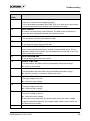
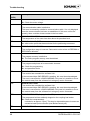
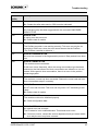
1
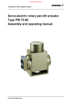
Function block for controlling SCHUNK-Modules for Siemens S7-300/400 Type FB 10 for Step 7 V1.4 User Manual 02/FB10/en/2011-03-11/HF Document last updated: 2010-03-11 Dear Customer, Congratulations on choosing a SCHUNK product. By choosing SCHUNK, you have opted for the highest precision, top quality and best service. You are going to increase the process reliability of your production and achieve best machining results – to the customer's complete satisfaction. SCHUNK products are inspiring. Our detailed assembly and operation manual will support you. Do you have further questions? You may contact us at any time – even after purchase. You can reach us directly at the mentioned addresses in the last chapter of these instructions. Kindest Regards, Your SCHUNK GmbH & Co. KG Precision Workholdind Systems Bahnhofstr. 106 – 134 D-74348 Lauffen/Neckar Tel. +49-7133-103-2503 Fax +49-7133-103-2189 [email protected] www.schunk.com 2 02/FB10/en/2011-03-11/HF Table of contents Table of contents 1 2 3 About this manual................................................................................................. 4 1.1 Purpose/validity .......................................................................................... 4 1.2 Target groups ............................................................................................. 4 1.3 Applicable documents ................................................................................ 4 Basic safety notes ................................................................................................ 5 2.1 Intended use .............................................................................................. 5 2.2 Personnel qualification ............................................................................... 5 Operating instruction of the FB10 ....................................................................... 6 3.1 Functions.................................................................................................... 6 3.2 Parameter Description ............................................................................... 7 3.3 Details on individual commands ............................................................... 11 3.4 3.3.1 Reference movement .................................................................. 11 3.3.2 Movement during manual operation JOG +/-............................... 11 3.3.3 Positioning via target position (Mode 0): ...................................... 11 3.3.4 Positioning via sequence (Mode 1):............................................. 11 3.3.5 Positioning via current value (Mode 2): ....................................... 12 3.3.6 Positioning movement via time value (Mode 3): .......................... 12 3.3.7 Positioning via GRIP-function (with Firmware version 1.20 or higher) (Mode 5): ..................................................................... 12 Note on the programming......................................................................... 13 4 Troubleshooting.................................................................................................. 14 5 Contact ................................................................................................................ 19 02/FB10/en/2011-03-11/HF 3 About this manual 1 1.1 About this manual Purpose/validity This manual is relevant for the FB10 function block and describes its safe and proper application in the controlling of SCHUNK-Modules. This manual applies exclusively for the FB10 function block. 1.2 Target groups Target group Task Manufacturer, operator Keep this manual available for the personnel at all times. Require personnel to read and observe this manual and the applicable documents, especially the safety notes and warnings. Skilled personnel, fitter Read, observe and follow this manual and the applicable documents, especially the safety notes and warnings. Table 1 1.3 Applicable documents You can find the following documents on our homepage: Document Purpose Assembly and Operating Manuals for SCHUNKModules Detailed information about the assembly, adjustment and commissioning of SCHUNK-Modules (drives, grippers, etc.). Software manual (MotionControl.pdf) Detailed information about the parameters and special features of the individual bus systems. General terms of business Including notes on the warranty. Table 2 4 02/FB10/en/2011-03-11/HF Basic safety notes 2 2.1 Basic safety notes Intended use For controlling the electrical SCHUNK-Modules (drive units, gripper) of the version 5.3, from firmware version 1.24 (using SMP) by Profibus using a Siemens S7-PLC, a special FB for all is designed. The FB10, including an instance-DB for every module, entails all necessary variables and functions for controlling all those modules. The FB10 is an interface for easily controlling a SCHUNKModule throughout the user application program. It is assumed that a basic set-up and the settings of the relevant parameters using the SCHUNK-MCDemo-Software had be done. Within the user application the FB10 has to be called cyclically once per module and has to be parameterized. Any other use or use exceeding that specified is an infringement of use for intended purpose. The manufacturer bears no liability for damage resulting from such use. 2.2 Personnel qualification The assembly, initial commissioning, maintenance, and repair of the module may be performed only by trained specialist personnel. Every person called upon by the operator to work on the module must have read and understood the complete Assembly and Operating Manual, especially chapter 2 “Basic safety notes”. This applies particularly to occasional personnel such as maintenance personnel. 02/FB10/en/2011-03-11/HF 5 Operating instruction of the FB10 3 3.1 Operating instruction of the FB10 Functions The FB 10 offers the following main functions: • • • • • • • • • Reading out the current status of the module. Continuous moving of the module in JOG-mode with the possibility for velocity adjustment. Positioning of the module by target position. Positioning of the module by sequence. Positioning of the module by current. Positioning of the module by time. Positioning of the module by velocity. Positioning of the module by GRIP-function. Stopping a current movement. Following further functions are available: • • • • • • • • 6 Possibility to set velocity, current, acceleration, and jerk. Easy choice of the kind of positioning mode by modeparameter. Automatic emergency stop of the module in case of false enable signal (no personal safety!). Quick output of the current values of position, current, and velocity of the module. Reading out the current fault massage for error detection, further error handling, or visualization on an OP. Possibility to distinguish between error and warning message. Watchdog for monitoring the time of command exchange between PLC and module (watchdog can be parameterized for output of error message or resending command within a specified time). Monitoring of the down-time of the Profibus communication between SPS and module. Should a down-time occur, an EMERGENCY STOP signal (no personal safety!) is sent to the module cyclically in order to counteract critical movements (in addition to module monitoring) when the communication is reestablished. 02/FB10/en/2011-03-11/HF Operating instruction of the FB10 3.2 Parameter Description Input Output Figure 1 Parameter Data Type Description I_ADDR WORD Entry-point address of the module (HEX). It should be noted that the initial characters of the module's entry-point and exit-point addresses entered in the hardware configuration must be identical. I_FL_CYCLE_BYTE INT The timing flag byte configured in the CPU (e.g. MB1 → 1). I_POS_MODE INT The operating mode determines the positioning type. The following options are currently available: 0 - Standard positioning 1 - Positioning via sequence 2 - Positioning via current value 3 - Positioning via time value 02/FB10/en/2011-03-11/HF 7 Operating instruction of the FB10 Parameter Data Type Description 4 - Positioning via velocity value 5 - Positioning via GRIP-function 8 I_ENABLE BOOL Enable (High-Signal evaluation). If the enable signal drops out, an EMERGENCY STOP command is sent to the module I_ACK BOOL Error acknowledgement (internal pulse control on rising edge). I_RESEND_CMD BOOL Should the module fail to answer a positioning command within the time period configured in I_RES_TIME, this parameter indicates whether the positioning command should be resent or whether an error message should be displayed (0 = deactivated with error message; 1 = resending activated). If resending does not apply, the error message prevents all other movement commands from being acknowledged. I_CMD_REF_MODUL BOOL Reference movement (internal pulse control on rising edge) I_CMD_JOG_PLUS BOOL Continuous movement in positive direction during manual operation (High-Signal evaluation). I_CMD_JOG_MINUS BOOL Continuous movement in negative direction during manual operation (High-Signal evaluation). I_CMD_START_POS BOOL Start of positioning in accordance with preselected mode (internal pulse control on rising edge). I_CMD_STOP_MOTION BOOL Current positioning procedure is halted (internal pulse control on rising edge). I_POS_JERK REAL Jerk (depending on the selected mode, it is transferred to the module immediately [unit as per setting in MCDemo]). I_POS_ACCELERATION REAL Acceleration (depending on the selected mode, it is transferred to the module immediately [unit as per setting in MCDemo]). 02/FB10/en/2011-03-11/HF Operating instruction of the FB10 Parameter Data Type Description I_POS_VELOCITY REAL Velocity (depending on the selected mode, it is transferred to the module immediately [unit as per setting in MCDemo]). I_POS_SEQUENCE INT Number of the desired sequence (dependent on the selected mode). I_POS_POSITION REAL Position value which dictates where the module should be positioned (dependent on the selected mode [unit as per setting in MCDemo]). I_POS_CURRENT REAL Current value which dictates where the module should be positioned (depending on the selected mode, it is transferred to the module immediately [unit as per setting in MCDemo]). I_POS_TIME REAL Time value which dictates where the module should be positioned (depending on the selected mode, it is transferred to the module immediately [unit as per setting in MCDemo]). I_RES_TIME S5Time If I_RESEND_CMD is activated and the module fails to respond to a positioning command, the time period which must elapse before the positioning command is resent. If I_RESEND_CMD is deactivated, the time period which must elapse before the error message is displayed (standard: 2 sec.). I_TIMER_WDOG TIMER Timer for internal evaluation of the watchdog functionality M_REFERENCED BOOL Feedback signal: module is referenced. M_IN_MOTION BOOL Feedback signal: module is in motion. M_PROG_ACTIVE BOOL Feedback signal: module is in programming mode M_WARNING BOOL Feedback signal: a warning is present. M_ALARM BOOL Feedback signal: an alert is present. M_BRAKE_ACTIVE BOOL Feedback signal: brake has been engaged 02/FB10/en/2011-03-11/HF 9 Operating instruction of the FB10 Parameter Data Type Description (optional). M_POS_REACHED BOOL Feedback signal: target position has been reached. M_ACT_POS REAL Feedback signal: current position value (this is not cyclically updated during the sinevector search). M_ACT_VELO REAL Feedback signal: current velocity (this is not cyclically updated during the sine-vector search). M_ACT_CURR REAL Feedback signal: prevailing current (this is not cyclically updated during the sine-vector search). M_ERROR WORD Feedback signal: error number Table 3 Parameters of the FB10 10 02/FB10/en/2011-03-11/HF Operating instruction of the FB10 3.3 3.3.1 Details on individual commands Reference movement A reference movement is completed. The type of referencing is defined once in the configuration data. A desired module movement can only be carried out after the module has been referenced. 3.3.2 Movement during manual operation JOG +/By implementing the JOG command, a continuous movement of the module is activated for as long as the command is present, with the preset velocity being taken into consideration. If the JOG signal is removed, the module stops. Any change made to the velocity while the module is moving is adopted immediately. The user must take responsibility in his user program for the separation between automatic positioning and JOG movements during manual operation. 3.3.3 Positioning via target position (Mode 0): Moves the module to a specified position. The position is set in the configured unit system. The positioning movement is based on the configured motion profile. When the position is reached, the output signal “M_POS_REACHED” is set. If new positioning parameters are entered during a movement, the movement might be temporarily halted. If you wish to enter new positions during a movement, e.g. to move along curves, the positioning should be performed using time parameters. 3.3.4 Positioning via sequence (Mode 1): A line from the saved program is executed. The desired sequence is selected in the input parameter “I_POS_SEQUENCE”. 02/FB10/en/2011-03-11/HF 11 Operating instruction of the FB10 Sequence here means a real target position as well as an arbitrary module command, which can be set via MCDemo. 3.3.5 Positioning via current value (Mode 2): A current movement is completed. Due to the controller structures used, the module can overspeed. If the module exceeds the configured maximum velocity, an ERROR occurs. 3.3.6 Positioning movement via time value (Mode 3): The module moves to a specified position. The position is set in the configured unit system. During the movement, new positions can be preset, which are then immediately moved to. When calculating the path, the nominal velocity and acceleration values as well as the actual velocity and acceleration values are taken into account. The velocity and acceleration values are adjusted in such a way that the position is reached within the specified time without exceeding the preset velocity and acceleration limits. For these types of movement, the motion profile is set to trapezoid. New position parameters can be entered during the movement. The new movement is subsequently calculated based on the entered parameters and the current actual velocity and acceleration values. This makes it possible to move along curved paths. 3.3.7 Positioning via GRIP-function (with Firmware version 1.20 or higher) (Mode 5): A gripping movement is completed (current in configured unit system). The command only works if subordinate current control is available. Gripping is also possible via a velocity movement or a positioning movement with subordinate current control 12 02/FB10/en/2011-03-11/HF Operating instruction of the FB10 3.4 Note on the programming The FB10 was created in such a way that it transfers any modified parameters to the module first of all, followed by the motion command. In spite of this, always ensure that the necessary parameters have already been transferred to the module prior to each motion command. You must ensure that no pulsed control commands are applied to the FB10. The reason for this is the specific behavior of the PLC when subjected to heavy utilization (e.g. “swallowing” of pulses during a cycle). Because some of the FB10's inputs create pulses themselves from the rising edge of the input signal, a static signal or an extended pulse is sufficient here. 02/FB10/en/2011-03-11/HF 13 Troubleshooting 4 Troubleshooting The following table shows possible error codes relating to the module and provides a description of each code. Error messages must generally be acknowledged with ACK. Error code (HEX) Description 1 INFO BOOT The module has booted successfully. (Info message. This is triggered following a complete failure of the logic voltage or following a restart by the internal watchdog.) If this message appears frequently during operation, the logic voltage should be checked. The performance driver could also be defective. 2 INFO NO FREE SPACE The available memory capacity is no longer sufficient. This error might occur during programming of internal sequential programs in cases where the EEPROM memory is depleted. With the SRU, it might occur in situations where the dynamically generated table used to record and optimize internal brake points exceeds the size of the available RAM memory. 4 INFO UNKNOWN COMMAND The sent command is not recognized. Check whether the command code is correct. Check whether the user is logged on correctly. (Certain commands are not known to all users.) 5 INFO FAILED The command has failed. All of the parameters are correct, but the execution of the command is not possible at this time due to other reasons, e.g. the module is in emergency stop mode. With MOVE POS TIME, this message appears if the parameters are correct, but the position cannot be reached with the values in the specified time. 6 INFO NOT REFERENCED The module is not referenced and can therefore not execute the command. The module must be referenced in order to carry out a positioning movement. 7 INFO SEARCH SINUS VECTOR A search is running for the space vector for the sine commutation. 60% of the maximum current is used for the phases. Following power-up of the device, this is carried out once before any movement commands are executed. 14 02/FB10/en/2011-03-11/HF Troubleshooting Error code (HEX) Description 8 INFO NO ERROR There are no other error messages pending. This is generated immediately after CMD_ACK if no other errors are present or if the module has moved outside of the software limit range. 10 INFO TIMEOUT A timeout occurred during communication. The data could not be sent, or more data was anticipated and was not received on time. 19 INFO CHECKSUM The checksum is incorrect, the data is invalid. 1D INFO MESSAGE LENGTH D-Len does not match the received data. 1E INFO WRONG PARAMETER One of the specified parameters is outside of the permitted range. If a parameter is found to be incorrect, the old parameters are retained, even if the others parameters are valid. 1F INFO PROGRAM END A sequential program has been closed. 70 ERROR TEMP LOW The temperature has fallen below the permissible temperature range. Warm up the module. 71 ERROR TEMP HIGH The temperature has risen above the permissible temperature range. Allow the module to cool down. Reduce the load. 72 ERROR LOGIC LOW The logic voltage is too low. Check the logic voltage. 73 ERROR LOGIC HIGH The logic voltage is too high. Check the logic voltage. 74 ERROR MOTOR VOLTAGE LOW The motor voltage is too low. Check the motor voltage. If this error occurs frequently, the power supply unit of the motor voltage might be underdimensioned or the voltage supply cables to the module are not dimensioned correctly. 75 ERROR MOTOR VOLTAGE HIGH 02/FB10/en/2011-03-11/HF 15 Troubleshooting Error code (HEX) Description The motor voltage is too high. Check the motor voltage. 76 ERROR CABLE BREAK The communication cable is defective. This error is caused by a defective communication cable. It is only displayed once the communication has been re-established. If this error occurs frequently, there could be a loose contact in the bus cable. 78 ERROR MOTOR TEMP The temperature of the motor has risen above the permitted level. C8 ERROR NO RAMP TYPE No valid motion profile has been selected for the positioning movement. D2 ERROR CONFIG MEMORY The configuration range is incorrect. Data could not be written to EEPROM or EEPROM is defective. D3 ERROR PROGRAM MEMORY The program memory is defective. The entire program memory must be deleted. D4 ERROR INVALIDE PHRASE The programmed phrase to be executed is incorrect. Check the programming and parameter limits. D5 ERROR SOFT LOW The module has exceeded the software limit. If the command byte CMD ERROR is pending, this must be acknowledged. The error is converted to a CMD WARNING. Only now is it possible to move the module away from the software limit using any motion command. D6 ERROR SOFT HIGH The module has exceeded the software limit. If the command byte CMD ERROR is pending, this must be acknowledged. The error is converted to a CMD WARNING. Only now is it possible to move the module away from the software limit using any motion command. D7 ERROR PRESSURE (Only applies for SRU) The compressed air has suddenly dropped or the coupling has broken. Check the compressed air. It should be at approx. 6 [bar]. This drop is detected because it causes an excessive brake point correction (see MotionControl.pdf). D8 16 ERROR SERVICE 02/FB10/en/2011-03-11/HF Troubleshooting Error code (HEX) Description The module requires maintenance. Contact the after-sales service. SRU must be lubricated. D9 ERROR EMERGENCY STOP An emergency stop has been triggered with the command CMD EMERGENCY STOP. DA ERROR TOW A towing error has occurred. Reduce load of module. DB ERROR VPC3 (module only) The Profibus controller is not working correctly. This error can only be detected by a DIAG user, since the error cannot be sent via the Profibus. (The Profibus controller is defective.) DC ERROR FRAGMENTATION An error has occurred in the fragmentation protocol. Data packets have been lost. DD ERROR COMMUTATION The module cannot commutate. If this error occurs frequently, either the wrong commutation type has been selected or the Hall sensors for block commutation are defective or not connected. With regard to sine commutation, there is an error in the position measuring system. DE ERROR CURRENT The maximum current has been exceeded. Reduce the motor load and introduce intermediate steps if necessary. DF ERROR I2T An I2T error has occurred. This error can only occur if I2T monitoring is activated. Reduce load of module. E0 ERROR INITIALIZE The module could not be initialized properly. Check configuration data. E1 ERROR INTERNAL An internal error has occurred. The Firmware is in an undefined status. This should never occur. If this error occurs, contact the service department and give exact details as to why the error may have occurred. 02/FB10/en/2011-03-11/HF 17 Troubleshooting Error code (HEX) Description E2 ERROR HARD LOW The module has reached a hardware limit. Acknowledge error. If the module is equipped with a brake, release it (MOVE_CURR) and move the module away from the hardware limit manually. If not equipped with a brake, simply move the module away from the hardware limit position manually. E3 ERROR HARD HIGH The module has reached a hardware limit. Acknowledge error. If the module is equipped with a brake, release it (MOVE_CURR) and move the module away from the hardware limit manually. If not equipped with a brake, simply move the module away from the hardware limit position manually. E4 ERROR TOO FAST The maximum velocity was exceeded during a current movement (motor is overspeeding). Reduce the specified current. FFFF ERROR COMMUN ICATION The FB10 is not able to communicate with the module. This can be because of a wrong selected communication parameter or if the module is not reachable. FFFF ERROR TIMEOUT COMMAND If resending is deactivated, this error appears if the module response is not received in a specified time. The error blocks any further motion commands. Acknowledge the error with ACK. Table 4 possible error codes 18 02/FB10/en/2011-03-11/HF Contact 5 Contact GERMANY – HEAD OFFICE CANADA DENMARK HUNGARY SCHUNK GmbH & Co. KG Spann- und Greiftechnik Bahnhofstrasse 106 – 134 D-Lauffen/Neckar Tel. +49-7133-103-0 Fax +49-7133-103-2399 [email protected] www.schunk.com SCHUNK Intec Corp. 190 Britannia Road East, Units 23-24 Mississauga, ON L4Z 1W6 Tel. +1-905-712-2200 Fax +1-905-712-2210 [email protected] www.ca.schunk.com SCHUNK Intec A/S Storhaven 7 7100 Vejle Tel. +45-43601339 Fax +45-43601492 [email protected] www.dk.schunk.com SCHUNK Intec Kft. Széchenyi út. 70. 3530 Miskolc Tel. +36-46-50900-7 Fax +36-46-50900-6 [email protected] www.hu.schunk.com AUSTRIA CHINA FRANCE INDIA SCHUNK Intec GmbH Holzbauernstr. 20 4050 Traun Tel. +43-7229-65770-0 Fax +43-7229-65770-14 [email protected] www.at.schunk.com SCHUNK GmbH & Co.KG Shanghai Representative Office 777 Zhao Jia Bang Road Pine City Hotel, Room 923 Xuhui District Shanghai 200032 Tel. +86-21-64433177 Fax +86-21-64431922 [email protected] www.cn.schunk.com SCHUNK Intec SARL Parc d´Activités des Trois Noyers 15, Avenue James de Rothschild Ferrières-en-Brie 77614 Marne-la-Vallée Cedex 3 Tel. +33-1-64 66 38 24 Fax +33-1-64 66 38 23 [email protected] www.fr.schunk.com SCHUNK India Branch Office # 80 B, Yeswanthpur Industrial Suburbs, Bangalore 560 022 Tel. +91-80-41277361 Fax +91-80-41277363 [email protected] www.in.schunk.com BELGIUM, LUXEMBOURG CZECH REPUBLIC GREAT BRITAIN, IRELAND ITALY SCHUNK Intec N.V./S.A. Bedrijvencentrum Regio Aalst Industrielaan 4, Zuid III 9320 Aalst-Erembodegem Tel. +32-53-853504 Fax +32-53-836022 [email protected] www.be.schunk.com SCHUNK Intec s.r.o. Ernsta Macha 1 643 00 Brno Tel. +420-545 229 095 Fax +420-545 220 508 [email protected] www.cz.schunk.com SCHUNK Intec Ltd. Cromwell Business Centre 10 Howard Way, Interchange Park Newport Pagnell MK16 9QS Tel. +44-1908-611127 Fax +44-1908-615525 [email protected] www.gb.schunk.com SCHUNK Intec S.r.l. Via Barozzo 22075 Lurate Caccivio (CO) Tel. +39-031-4951311 Fax +39-031-4951301 [email protected] www.it.schunk.com 02/FB10/en/2011-03-11/HF 19 Contact JAPAN POLAND SOUTH KOREA SWITZERLAND, LIECHTENSTEIN SCHUNK Intec K.K. 45-28 3-Chome Sanno Ohta-Ku Tokyo 143-0023 Tel. +81-33-7743731 Fax +81-33-7766500 [email protected] www.tbk-hand.co.jp SCHUNK Intec Sp.z o.o. Stara Iwiczna, ul. Słoneczna 116 A 05-500 Piaseczno Tel. +48-22-7262500 Fax +48-22-7262525 [email protected] www.pl.schunk.com SCHUNK Intec Korea Ltd. # 907 Joongang Induspia 2 Bldg., 144-5 Sangdaewon-dong Jungwon-gu, Seongnam-si Kyunggi-do, 462-722 Tel. +82-31-7376141 Fax +82-31-7376142 [email protected] www.kr.schunk.com SCHUNK Intec AG Soodring 19 8134 Adliswil 2 Tel. +41-44-7102171 Fax +41-44-7102279 [email protected] www.ch.schunk.com MEXICO, VENEZUELA PORTUGAL SPAIN TURKEY SCHUNK Intec S.A. de C.V. Av. Luis Vega y Monroy # 332 Fracc. Plazas de Sol Santiago de Querétaro, Qro. 76099 Tel. +52-442-223-6525 Fax +52-442-223-7665 [email protected] www.mx.schunk.com Sales Representative Victor Marques Tel. +34-937-556 020 Fax +34-937-908 692 Mobil +351-963-786 445 [email protected] www.pt.schunk.com SCHUNK Intec S.L. Foneria, 27 08304 Mataró (Barcelona) Tel. +34-937 556 020 Fax +34-937 908 692 [email protected] www.es.schunk.com SCHUNK Intec Bağlama Sistemleri ve Otomasyon San. ve Tic. Ltd. Şti. Küçükyali Iş Merkezi Girne Mahallesi Irmak Sodak, A Blok, No: 9 34852 Maltepe, Istanbul Tel. +90-216-366-2111 Fax +90-216-366-2277 [email protected] www.tr.schunk.com NETHERLANDS SLOVAKIA SWEDEN USA SCHUNK Intec B.V. Speldenmakerstraat 3d 5232 BH „s-Hertogenbosch Tel. +31-73-6441779 Fax +31-73-6448025 [email protected] www.nl.schunk.com SCHUNK Intec s.r.o. Mostná 62 919 01 Nitra Tel. +421-37-3260610 Fax +421-37-6421906 [email protected] www.sk.schunk.com SCHUNK Intec AB Morabergsvägen 28 152 42 Södertälje Tel. +46-8 554 421 00 Fax +46-8 554 421 01 [email protected] www.se.schunk.com SCHUNK Intec Inc. 211 Kitty Hawk Drive Morrisville, NC 27560 Tel. +1-919-572-2705 Fax +1-919-572-2818 [email protected] www.us.schunk.com 20 02/FB10/en/2011-03-11/HF