1
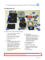
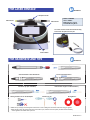
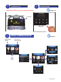
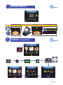
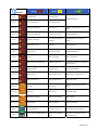
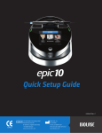
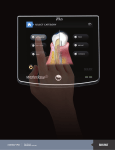
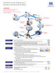
Quick Setup Guide
5400442 Rev. A
MT Promedt Consulting GmbH
Altenhofstrasse 80
D-66386 St. Ingbert/Germany
+49 6894 581020
www.mt-procons.com
BIOLASE, Inc.
4 Cromwell
Irvine, CA 92618 USA
949.361.1200 | 888.424.6527
www.biolase.com
For detailed instructions always refer to the EPIC™10 User Manual
SYSTEM PARTS LIST
5
9
6
8
4
7
10
11
3
13
12
14
2
1
15
The EPIC 10 laser system includes the following: 1. Laser Console (lithium ion battery
pack already installed)
2. Screen Protectors box (Peel-off
clear screen cover - qty. 30)
3. Delivery System box
4. Tips box
5. Surgical Handpiece box (contains
two (2) Surgical Handpieces)
6. Three (3) pairs of protective laser
eyewear (two (2) pairs of doctor
safety glasses, one (1) pair of
darker patient safety glasses)
7. DC power supply and power cord
(one (1) US and one (1)
International)
8. User Manual
9. Welcome Kit (Welcome Letter,
BIOLASE store information, Quick
Setup Guide, Guide to Online
Training & Product Registration
Card, Tip User Guide, Limited
Warranty Information)
10. Laser Warning Sign
11. Tip Initiation Kit
12. Remote Interlock cable
13. Philips-head screwdriver (for
installing Footswitch batteries)
14. Footswitch
15. AAA batteries (2)
CAUTION: Federal Law restricts this device to sale by or on the order of a dentist
or physician or other licensed medical practitioner.
5400442 Rev. A
THE LASER CONSOLE
SECTION 2.3
Handpiece Holder
LED Indicator
LED Indicator
Amber > STANDBY
Green > READY
Blinking Green > Lasing
Activated Blinking Blue >
The Laser Console arrives with the fiber already
inserted into the optical access port.
Control Button
THE HANDPIECE AND TIPS
SECTION 2.8
Fiber Shaft Protective Cap
Handpiece
Surgical Handpiece Fully Assembled
Disconnect the Handpiece
Insert Fiber Tip (turn clockwise) Remove Fiber Tip (turn counterclockwise)
Seating the Fiber Tip into the Handpiece Bending the Tip
Aiming Beam *
* ●When the tip is straight, the aiming beam will look like a circle outlining the area where main laser energy is applied.
●When the tip is bent, the aiming beam will look more like a spot, and the main laser power (invisible infrared radiation)
will be applied in the middle of the spot area.
5400442 Rev. A
POWER ON
1
NOTE: Before initial use, you must charge the battery! 2
PASSWORD SECTIONS 4.1, 4.2
Power Switch
Enter 888
3
TOUCH SCREEN DISPLAY
Wireless Signal
Strength
SECTION 4.11
Laser Console
Battery Strength
Settings
5400442 Rev. A
INITIATE THE TIP
4
SECTION 7.3
1 2 3
4
5 5
PAIRING (IF NECESSARY)
SECTION 4.4
(If not paired)
1 2 3 4 5400442 Rev. A
Message SECTION 11 Error 1 Thermistor Open Reason Thermistor Open Error 2 Fix Call BIOLASE Service Thermistor Shorted Thermistor Shorted Shutdown Temperature System too hot Allow 5‐10 mins for laser to cool down Laser Current High/ Low Output is out of specs Call BIOLASE Service FS shorted in Standby FS is partially pressed or is damaged Press/Release FS or call Biolase Service ON/OFF button Stuck Key stuck Press Front key Flash Corrupted Memory Corrupted Call BIOLASE Service No Fiber Fiber not inserted Plug in Trunk Fiber Lost Footswitch Communication Wireless Interference Reposition console or FS to improve communication Emergency Switch E‐Switch Pressed Press E‐Switch Again Remote Interlock Remote interlock open Check Remote Interlock closed Battery Critically Low Battery Critically Low Plug in DC supply Temp High System is hot Allow 5‐10 mins for laser to cool down Battery Low Battery is low Plug in DC supply Battery Not Connected Battery not connected Plug in Battery FS Battery Low Battery on FS low Replace FS battery Wireless Not Paired No wireless connect Re‐establish pairing (see Sec 4) System is not in READY mode Press the Control Button in any procedure screen Error 3 Error 4 Error 5 Error 6 Error 7 Error 8 Error 9 Error 10 Error 11 Error 12 Warning 1 Warning 2 Warning 3 Warning 4 Alert 1 Alert 2 System must be in READY mode to lase 5400442 Rev. A