1
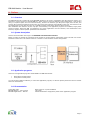
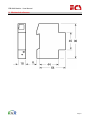
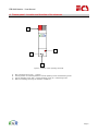
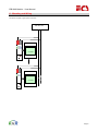
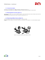
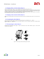
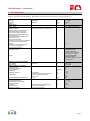
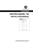
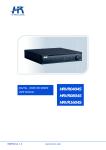
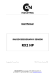
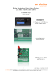
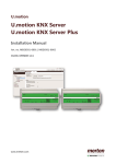
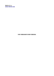
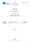
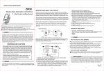
EIB-KNX Module – User Manual EIB-KNX Module User Manual Preliminary Page 1 EIB-KNX Module – User Manual 1. Index 1. 2. 2.1. 2.2. 2.3. 2.4. 3. 4. 5. 5.1. 5.2. 5.3. 5.4. 5.5. 5.6. 5.7. 6. Index ................................................................................................................................................2 Preface ..............................................................................................................................................3 Overview............................................................................................................................................3 System description ..............................................................................................................................3 Application programs ...........................................................................................................................3 Documentation ...................................................................................................................................3 Mechanical reference ...........................................................................................................................4 Frontal panel - Location and function of the elements ..............................................................................5 Mounting and Wiring ...........................................................................................................................6 General description .............................................................................................................................7 Mounting DIN-rail devices (Figure 2) .....................................................................................................7 Dismounting DIN-rail devices (Figure 2) .................................................................................................7 Slipping off bus connection blocks (Figure 3) ..........................................................................................8 Slipping on bus connection blocks (Figure 3) ..........................................................................................8 Connecting bus cables (Figure 3) ..........................................................................................................8 Disconnecting bus cables (Figure 3).......................................................................................................8 Technical reference .............................................................................................................................9 Page 2 EIB-KNX Module – User Manual 2. Preface 2.1. Overview The EIB-KNX Module is a DIN rail mount KNX/EIB interface to be used in combination with the electricity meters. It is intended to connect meters to the KNX/EIB bus, widely used for home and building control applications. Only the bus wiring is requested (black and red connection block), because the interface gets the power supply from the bus, and receives the measurement data from the meter by means of the infrared port available on the side. The interface must be installed side by side with the meter. It is suitable for both single-phase and three-phase meters. After installation the interface requires a proper commissioning: two application programs are available, single phase and three phase. With ETS (EIB Tool Software) the proper application must be selected, and downloaded to the interface, together with its specific parameters and addresses. 2.2. System description This document describes the usage of the EIB-KNX communication interface. Below you have an example of connection for the module. A minimal system configuration require at least one counter beside the module and a PC master station to control the communication and the configuration. 2.3. Application programs There are two application programs downloadable into EIB-KNX Module: Single phase models profile Three phase models profile You use the ETS (EIB tool software) to select the application program, to allocate specific parameters and to transfer these into the Interface. 2.4. Documentation Quick start guide EIB-KNX Module – User manual EIB-KNX Applications – Manual Basic notes for a quick installation This guide Manual dedicated to single/three phase meter application program Page 3 EIB-KNX Module – User Manual 3. Mechanical reference Page 4 EIB-KNX Module – User Manual 4. Frontal panel - Location and function of the elements A C B D Figure1: Location of the operating elements A. B. C. D. Bus connection block. Red = +, Black = -. Learning button for switching between normal operating mode and addressing mode. Led for operating mode. Off = normal operating mode, On = addressing mode. Slide for installing/removing the interface on DIN rail. Page 5 EIB-KNX Module – User Manual 5. Mounting and Wiring The power supply is got by the bus lines. EIB-KNX bus Counter Counter Page 6 EIB-KNX Module – User Manual 5.1. General description The device can be installed on any DIN rail complying with EN 60715-TH35-7,5. The connection to the bus line is established via the bus connector terminal (red-black) on the top side. 5.2. Mounting DIN-rail devices (Figure 2) Slide the device (Figure 2, B1) onto the DIN-rail (Figure 2, B2) and swivel back the device until the slide clicks into place audibly. Connect the bus line with the black-red bus connector terminal (Figure 1, A). 5.3. Dismounting DIN-rail devices (Figure 2) Remove the black-red bus connector terminal (Figure 1, A) from its socket. Press down the slide (Figure 2, C3) with a screw-driver and swivel the device (Figure 2, C1) from the DIN-rail (Figure 2, C2). C2 B2 C1 B1 C3 Figure 2: Mounting and dismounting a DIN-rail device Page 7 EIB-KNX Module – User Manual 5.4. Slipping off bus connection blocks (Figure 3) - The bus connection block (Figure 3, D2) is situated on the top of the device (Figure 3, D1). - The bus connection block (Figure 3, D2) consists of two components (Figure 3, D2.1 and D2.2) with four terminal contacts each. Take care not to damage the two test sockets (Figure 3, D2.3) by accidentally connecting them to the bus cable or with the screw-driver (e.g. when attempting to unplug the bus connection block). - Carefully put the screw-driver to the wire-inserting slit of the bus connection block's grey component and pull the bus connection block (Figure 3, D2) from the device (Figure 3, D1). 5.5. Slipping on bus connection blocks (Figure 3) - Slip the bus connection block onto the guide slot and press the bus connection block (Figure 3, D2) down to the stop. 5.6. Connecting bus cables (Figure 3) - The bus connection block (Figure 3, D2) can be used with single core conductors Ø 0,6 ... 0,8 mm. - Remove approx. 5 mm of insulation from the conductor (Figure 3, D2.4) and plug it into the bus connection block (Figure 3, D2) (red = +, black = -). 5.7. Disconnecting bus cables (Figure 3) - Unplug the bus connection block (Figure 3, D2) and remove the bus cable conductor (Figure 3, D2.4) while simultaneously wiggling it. D2 D2.3 D2.1 D2.2 D2.4 D2 5 mm D2 D1 D2 D D2.4 Figure 3: Connecting and disconnecting the bus wires Page 8 EIB-KNX Module – User Manual 6. Technical data Data in compliance with IEC 60664-1, EN 50090-2-2, EN 61000-6-2, EN 61000-6-3 and EN 61000-4-2 General characteristics • Housing • Mounting • Depth Power supply • Power supply Operating features • Models available: • Communication in compliance with EIB-KNX standard for home and building control. KNX Certification. • Energy registers transmitted as float values (DPT13.xxx) • Power registers transmitted as float values (DPT14.xxx) • Status bytes available • Energy account remote reset available (not active for some energy meters models) • Suitable for both single-phase and three-phase energy meters • Configuration via ETS3 EIB-KNX bus connection • Connection block DIN 43880 EN 60715 DIN 35 mm mm Through bus connection for energy and power measurements yes Black/red screwless connection block for connection to Twisted Pair, single core 0.6…0.8mm Recommended cable: KNX/EIB certified or recognized cable 1x2x0,8 mm or 2x2x0,8 mm • Cable Interface to measuring instrument - HW Interface - SW Protocol Safety accordino to iec 60664 • Degree pollution • Overvoltage category • Working voltage • Clearance • Creepage distance • Test voltage • Housing material flame resistance Environmental conditions - Operating temperature - Limit temperature of storage - Relative humidity - Vibrations - Protection class - Degree of protection 1 module DIN rail 70 Optical IR in equipment on printed wiring boards (not coated) impulse (1,2/50 μs) peak value 50 Hz 1 min UL 94 Sinusoidal vibration amplitude at 50 according to IEC 60664-1 housing when mounted No. VDC(max.) mm mm mm kV kV class ˚C °C % mm 2 (Tx, Rx) Proprietary 2 II 30 1.5 2.1 1.5 2.5 1.35 V0 0 … +55 -25 ... +70 ≤ 80 0.25 II IP20 Page 9