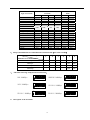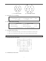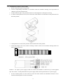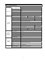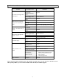
1
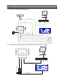
Operation Manual of
Outdoor High-Speed Pan/Tilt
with Infrared Lighting
Pleased read the manual carefully before using the product.
I.
Notes for Attention
1.
Read the manual carefully before installing the product.
2.
There are two input ways of power supply: DC12V (vehicle) and AC24V (normal pan/tilt). Detailed
connections refer to the description files.
3.
There are sophisticated optical and electronic components inside the product. Avoid incorrect operation
methods such as heavy pressing or strong vibration during the course of transportation, store and installation
otherwise the product could be damaged.
4.
Please do not dismount components inside the product to avoid occurrence of trouble. There is no part inside
the product, which needs repair by customer himself.
5.
Observe all electric safety standards in application and adopt special power supply attached the product.
RS-485 control signal and video signal should be kept enough distance with the high voltage devices and
cables during the course of transmission, and take protection measures such as anti-lightning and surging etc.
if necessary.
6.
Do not apply the product under the state exceeding limited temperature, humidity or specifications of power
supply.
7.
Do not aim the camera at the sun or very bright object, aim or monitor bright and still object for a long time
whether the power supply of the camera is switched on or off.
8.
Clean out dirt with special lens tissue if dust is stuck on the lens.
II.
Description of Functions
This product is a high-tech monitor and controller which incorporates high definition color camera, universal
variable pan/tilt, infrared lighting, multi-functional decoder, character superimposing, alarm input/output into a
whole, reduces interconnections to a great extent among parts in the system and rises up the reliability of the
system. In addition it has advantages of easy installation and maintenance, beautiful appearance, lightweight and
flexible, simple operation etc.
1.
Integrated Multi-Protocol Decoder
a. The built-in decoder integrates 16 kinds of communication protocols in maximum. The baud rate of
communication is adjustable. It has strong universality and is compatible with multiple common systems
only by simple setting on the dip-switch.
b. RS485 serial control: addresses of the pan/tilt 1 – 1023.
2.
Integrated Panoramic Pan/Tilt
a. To rotate continuously in unlimited 360ºhorizontally with speed from 0.9 – 60 rad/s and from - 90º-90º
vertically with manual speed of 40 rad/s.
b. Smooth running at low speed with super lower noise. Images have no fluttering.
c. Panoramic monitor without black spot and the positioning accuracy can reach ±0.1°.
3.
High Degree of Intelligence
a.
Preset memory has as much as 128 positions. Data are kept in memory even power is failure.
b. Horizontal scan between two positions are supported. Scan speed can be altered and direction of pan can
be selected freely. The pan/tilt can make scan larger or smaller than 180° between any two positions with
adjustable speed.
c.
Six groups of programmable patrol pattern are available with 16 preset positions each. The running speed
and retained time for each preset position are adjustable respectively.
d. Self-study function of pattern. The system can simulate the PTZ route of user’s operation within 40
1
seconds and data are kept in memory even power is failure.
e.
Character superimposing function. It can display the address of the pan/tilt, title of the preset position etc.
f.
Long focus speed-limited function. The pan/tilt can adjust automatically the manual control speed
depending on the focal length of the camera. The larger the magnification times, the slower the manual
control speed thus to ensure searching the target rapidly and accurately.
g. Integrated multiple protocols. A lot of communication protocols are integrated inside the pan/tilt with
selectable baud rates from 2400 bps to 19200 bps.
4.
Camera Function: Refer to Camera
a. Control Mode of Focal Length: the user can manually adjust the focal length of the camera.
b. Control of Magnification:the user can “pull up” or “push away” the lens
c. Backlight Compensation: in case the lit object has dark background and couldn’t be displayed clearly,
the user can switch on the backlight compensation .
d. White Balance: in case images have distorted color on the screen, the user can set various kinds of
modes by orders. There are six modes available for selection: ① indoor modemm ② outdoor mode
③ trigger mode
④ auto tracking white balance ⑤ manual white balance ⑥ automatic mode.
e. AE Mode:manual/automatic setup.
f.
Setup of Low Illumination: normally the camera operates under normal condition. In case when ambient
illumination is lower than 1 LUX, the camera can automatically switch into zero illumination state . You
can also make the camera under the zero illumination state manually.
g. Other function: refer to different camera by using system menu to control.
5. Alarm Input/Output (only when used as normal pan/tilt, AC24V input)
a.
Four normal-open alarm inputs and close alarm.
b.
One group of the alarm output: normal-open and normal-close style.
c.
When the system identifies the alarm signal, it can start the pan/tilt and the camera immediately as per the
setup of the program, and switch the image in the alarm zone into the main monitor, adjust the position of
the alarm position, monitor the preset position and reflect conditions of the alarm zone as fast as it can.
2
d. The alarm input should be the input signal with the switch type. Any other types of the input signal
(such as voltage signal) could damage the dome camera. In case multiple channels have alarm
signals, the pan/tilt shall response upon them on by one with the interval of 2 seconds. The pan/tilt
shall do not response upon functions such as “pan”, “patrol” and “self-study” when the alarm
signal in inputted.
6.
Infrared System
a.
The infrared system is normally under automatic control state. The infrared lamp shall act followed by
open/close of the low illumination of the camera;
b. The open/close state of the infrared lamp can be changed by the menu manually;
c.
The default option on the menu of the infrared lamp is OFF. Normally the system detects external
illumination and opens/closes the infrared lamp automatically. If the user changes the option of the
infrared lamp into ON, the infrared system is changed into the manual control; if changing back into the
automatic control, the user should set the option on the menu of the infrared at OFF.
d.
When being at critical illumination, as the infrared can affect the illumination of the camera, the
oscillation of open/close of the low illumination of the camera can be caused. In order to suppress such a
state effectively, the system shall open the infrared forcibly for 30 minutes. If the automatic state of the
infrared is needed, the user should change the option on the menu of the infrared at OFF.
III.
1.
Setup of the Menu of the Pan/Tilt
Basic Operation of the Menu
1.1
Open the main menu by the control keyboard or the matrix through the order “calling the 64th preset
position” or the order “calling the 1st preset position” in two fast and consecutive times.
1.2
When the menu is displayed on the screen, operate “TILT UP”, “TILT DOWN” to move the cursor to the
option to be set; and operate “PAN LEFT”, “PAN RIGHT” to modify contents or order to enter into the said
option.
1.3
To speed up operation by making the joystick towards one direction for more than one second.
1.4
All setup on the menu could not be lost even the power is failed.
1.5
Special uses can be seen from the description of the menu.
2.
Setup of the Menu
2.1 MAIN MENU
2.1.1
DISPLAY SETUP: to enter into the sub-menu of the display setup which can set the ID display, title
3
display of the presser position and the display of the camera itself.
2.1.2
MAI N MENU
CAMERA SETUP: to enter into the sub-menu of the common data
of the camera.
2.1.3
CONTROL SETUP: to enter into the sub-menu of the control data of
the pan/tilt.
2.1.4
PROGRAM: to enter into the sub-menu of the enhance function of
the menu.
2.1.5
PAL CAMERA: to switch modes of PAL/NTSC, being identical with
that of the camera.
2.1.6
CAM DEFAULT SET: to recover to the default setup of the camera.
2.1.7
DOME RESET: to reset the system.
2.1.8
EXIT: to exit the main menu.
2.2
2.2.1
1. DI SPLAY SETUP
2. CAMERA SETUP
3. CONTROL SETUP
4. PROGRAM
5. PAL CAMERA
6. CAM DEFAULT SET
7. RESET PT
8. EXI T
DISPLAY SETUP
ID DISPLAY: when it is set at ON, the monitor shall display the
address of the pan/tilt such as “CAM 001”. The default is ON
when power supply is switched on.
2.2.2
ID POS: to set the display position of the pan/tilt, which can be
at four corners of the screen such as TOP-L (upper left), TOP-R
(upper right), BOTT-R (bottom left) and BOTT-L (bottom right).
2.2.3
TITLE DIS: when it is set at ON, the title of the preset position
can be displayed on the left side of the screen when calling the preset position, such as “NO.001
ABCDEFGH”.
If no title of the position, then only “NO. 001” is displayed. The modification of the title
of the preset position can be set at the PROGRAM option on the menu.
2.2.4
TITLE POS: to set the display position of the title of the preset position from the 1st line to the 10th line.
The 1st line is at the top of the screen.
2.2.5
CAM DISPLAY: when it is set at ON, the display of the camera itself can be opened.
2.2.6
RETURN: to return to the main menu.
2.3
2.3.1
CAMERA SETUP
SLOW SHUTTER: frame accumulation function with options of
manual/automatic. Under automatic state when the display of the
camera is opened, ASS shall be displayed on the screen.
2.3.2
BACK LIGHT: backlight compensation open/close.
2.3.3
ICR SHOT: low illumination. ON – manual / AUTO – automatic.
2.3.4
IRIS: to set up automatic iris. AUTO – automatic / MANU – manual.
2.3.5
D-ZOOM:to set up digital zoom. ON – open / OFF – close.
2.3.6
FOCUS: to set up automatic focusing. AUTO – automatic / MANU –
manual.
2.3.7
WB SET: ATW / INDOOR / OUTDOOR / ONEPUSH / AUTO / MANU.
2.3.8
MENU OF CAM: this option is empty.
2.3.9
RETURN: to return to the main menu.
2.4 CONTROL SETUP
2.4.1
AUTO FILP:NULL (no such a function).
2.4.2
ALARM: ON/OFF: Turn on or Turn off the alarm input function.
4
2.4.3
PRESET PIC: NULL (no such a function).
2.4.4
HOME OPTION: to enter into the sub-menu of automatic home
function.
2.4.4.1
AUTO HOME: when it is set at ON, the automatic home is opened. It
means if the user has no any function in a period of time, the pan/tilt
shall return home (HOME). The pan/tilt couldn’t return home
automatically if the pan/tilt is at patrol state. If no home returning is
needed when the pan/tilt is under stop state, set this option at OFF.
2.4.4.2
HOME POS: HOME is the returning position. If some scene is
CONTROL SETUP
1. AUTO FI LP
2. ALARM
3. PRESET PI C
4. HOME OPTI ON
5. I R_LED
6. EXI T
ON
ON
MOVE
OFF
needed to set as HOME, call this scene on the camera and set it as the
preset position 3, then call up the menu and enter into this sub-menu, and change the figure after HOME
POS into 3. If you need to activate the automatic home, do not forget
HOME OPTI ON
to set AUTO HOME at ON. HOME POS can be preset positions from
1 to 63, and 65 to 128.
2.4.4.3
DWELL TIME: to set the time of automatic home, that is, if no
control within the set time, it shall return home. The time can be from
1 to 99 minutes.
1. AUTO HOME
2. HOME POS
3. DWELL TI ME
4. RETURN
ON
01
05 MI N
2.4.4.4
RETURN: to return the menu one level upward.
2.4.4.5
The default option on the menu of the infrared lamp is OFF. Normally the system detects external
illumination and opens/closes the infrared lamp automatically. If the user changes the option of the
infrared lamp into ON by the menu, the infrared system is changed into the manual control; if changing
back into the automatic control, the user should set the option on the menu of the infrared at OFF.
2.4.5
2.5
2.5.1
RETURN: to return to the main menu.
PROGRAM
AUTO PAN START POS: to set the start position of the pan between
two positions. After entering you can move the dome camera by the
joystick. Push CLOSE button you can store current position and
return.
2.5.2
AUTO PAN END POS: to set the end position of the patrol between
two positions. After entering you can move the pan/tilt by the joystick.
Push CLOSE button you can store current position and return.
2.5.3
RUN AUTO PAN: to pan between two positions. Please set the start
position and the end position of the pan first. If the start position is
just the end position, the dome camera shall make 360° pan. The
speed of the pan is divided into six grades: FAST / NORMAL / SLOW / -FAST / -NORMAL / -SLOW.
The first three grades are the pan less than 180° while the rear three grades are the pan larger than 180°.
Adjust speed by PAN LEFT/PAN RIGHT and press OPEN button to exit the menu. The start position and
the end position of the pan can be set up by options 1 and 2 of the menu.
2.5.4
SET TITLE: to edit the title of the preset position. Only first 63 positions can have their titles. Select
the number of the preset positions by PAN LEFT/PAN RIGHT and press OPEN button to enter into the
edit state. Operations under the edit state are shown below.
2.5.5
SET PATROL: to edit patrol data of multiple positions. Select the number of the pattern by PAN
LEFT/PAN RIGHT and press OPEN button to enter into the edit state. Operations under the edit state are
shown below.
5
2.5.6
RUN PATROL: to run patrol of multiple positions. Select the number of the pattern by PAN LEFT/PAN
RIGHT and press OPEN button to exit the menu.
2.5.7
RECORD PATTERN: to edit self-study of patrol. It can remember PTZ operation in 40 seconds in
maximum. When the 40th second is up or press CLOSE button, the edit is terminated.
2.5.8
RUN PATTERN: to run self-study pattern. After running it shall exit the menu. Control the joystick to
terminate its running.
2.5.9
3.
RETURN: to return to the main menu.
Appendix to the Menu
Operation of Multiple Patrol Positions under Edit State.
After entering into Edit state, operations on the
screen are as follows:
The prompt messages are displayed on both op and bottom lines and information of every pattern is displayed in
the middle of the screen. One line includes data of two patrol positions. Move the cursor by PAN LEFT/RIGHT
and change values by TILT UP/DOWN. Press down buttons for more than one second to speed up operation.
Press CLOSE button to exit the Edit state and store the revisions. The program can search the first position where
POS is “---”, and store data in front of it and regard data after it ineffective. Look the above drawing for example,
the program stores first four patrol positions. The settable range of POS is from 1 to 63 and 65 to 128. When POS
is “---“, it means the range of the patrol is finished. The settable range of SP is from 0 to 8 (0 is the same with 1
and has the fastest speed while 8 has the lowest speed). The settable range of TM is from 0 to 99 seconds.
NO
POS
SP
TM
–
–
–
–
No.of Patrol Position
No.of Preset Position
Leaving Speed
Dwell Time
After entering into Edit state,following information displays on the screen:
EDIT AREA: one line includes data of two patrol positions.
SEQ:01
– It means current set sequence is 1
CLOSE:EXIT – Press CLOSE to exit Edit state
Operation of Title of Preset Position under Edit State.
After entering
into Edit state, the display on the screen is shown as follows: from the
drawing we can find the current setup is the first preset position with the title
of “NO TITLE”. Move the cursor by PAN LEFT/RIGHT and change values
by TILT UP/DOWN. Press down buttons for more than one second to speed
up operation. Press CLOSE button to exit the Edit state and store the
revisions. The title of the preset position can include 8 characters in
maximum such as 0-9, A-Z, +, - and blank.
Note: the first letter should be
0-9 or A-Z, otherwise it means the title of the preset position should be
6
deleted. When calling the preset position, it only displays “NO.XXX”
without the title.
IV.
Setup of the Intelligence Full-Dome Pan/Tilt
Before installing the product, first of all confirm the communication protocol and the baud rate of the main
machine in the system, then set the dip-switch SW2 of the pan/tilt to be identical with that of the system, set the
address of the pan/tilt on SW1 and the type of the communication protocol and the baud rate on SW2.
Dip-Switch of Address
Dip-Switch of Protocol
(Figure 1)
1.
Terminal Resistor:
The jumper JP1 is the option switch of 120 Ω terminal resistor of the bus RS485. When it is at 2—3 state, 120
Ω terminal resistor is opened and no bus 485 is connected; when it is at 1—2 state, 120 Ω terminal resistor is
connected in parallel with the bus 485. In the bus RS485 system, there is only one pan/tilt, which has the terminal
resistor to be connected in the circuit and other pan/tilts whose terminal resistors are opened so as to increase the
reliability of the system. Generally, the terminal resistor of the pan/tilt at the farthest end from the control circuit is
connected and all terminal resistors of other devices are opened.
2. Power Supply Panel for the Vehicle Pan/Tilt:
a.
Input voltage is DC10.5-18V, Iin≥3.5A;
b.
No alarm input and output.
JP1
connect
1
2
3
JP1
1
2
3
JP1 1-2 2-3
120R ON OFF
DC/DC
Converter
Code
ON
1
2
3 4
5
6
7 8
DIP
ON
9 10
1
DIP
2
3
3.Power Supply Panel for the Vehicle Pan/Tilt:
:
a.
Input voltage is AC24V, Iin≥1.75A;
7
4 5
6
b.
With alarm input and output;
c.
External synchronization.
The jumper JP2 is the connection terminal of the external synchronization of the camera, which provides
synchronic signal to the internal camera. When it is at 1—2 state, the external synchronization is introduced into
the internal camera; when it is at 2—3 state the external synchronization has no action upon the internal camera. If
the system adopts AC24V power supply, the jumper should be set at 1—2 state; if DC power supply is applied, the
jumper should be set at 2—3 state.
3
3
2
JP2
JP1
1
JP1 1-2 2-3
120R ON OFF
1
2
3
1-2 2-3
ON OFF
1
JP1
1
2
3
External
sync
2
JP2
Code
ON
1
2
3
4
5
6
7
8
DIP
ON
9 10
1
DIP
2
3
4
5
6
4.Dip-Switch of Address:
Dome
Address
1
2
3
4
5
6
7
8
9
10
11
12
13
14
15
16
17
18
…
1023
States of Dip-Switch
DIP-1
ON
OFF
ON
OFF
ON
OFF
ON
OFF
ON
OFF
ON
OFF
ON
OFF
ON
OFF
ON
OFF
DIP-2
OFF
ON
ON
OFF
OFF
ON
ON
OFF
OFF
ON
ON
OFF
OFF
ON
ON
OFF
OFF
ON
DIP-3
OFF
OFF
OFF
ON
ON
ON
ON
OFF
OFF
OFF
OFF
ON
ON
ON
ON
OFF
OFF
OFF
DIP-4
OFF
OFF
OFF
OFF
OFF
OFF
OFF
ON
ON
ON
ON
ON
ON
ON
ON
OFF
OFF
OFF
ON
ON
ON
ON
DIP-5
OFF
OFF
OFF
OFF
OFF
OFF
OFF
OFF
OFF
OFF
OFF
OFF
OFF
OFF
OFF
ON
ON
ON
DIP-6
OFF
OFF
OFF
OFF
OFF
OFF
OFF
OFF
OFF
OFF
OFF
OFF
OFF
OFF
OFF
OFF
OFF
OFF
…
ON
ON
8
DIP-7
OFF
OFF
OFF
OFF
OFF
OFF
OFF
OFF
OFF
OFF
OFF
OFF
OFF
OFF
OFF
OFF
OFF
OFF
DIP-8
OFF
OFF
OFF
OFF
OFF
OFF
OFF
OFF
OFF
OFF
OFF
OFF
OFF
OFF
OFF
OFF
OFF
OFF
DIP-9
OFF
OFF
OFF
OFF
OFF
OFF
OFF
OFF
OFF
OFF
OFF
OFF
OFF
OFF
OFF
OFF
OFF
OFF
DIP-10
OFF
OFF
OFF
OFF
OFF
OFF
OFF
OFF
OFF
OFF
OFF
OFF
OFF
OFF
OFF
OFF
OFF
OFF
ON
ON
ON
ON
SW1 is used to set the addresses of the pan/tilt which has the range from 1 to 1023. From DIP-10 to DIP-1 it
corresponds to a binary number with 10 bits in which the highest bit is DIP-10 and the lowest bit is DIP-1. The
state ON for each bit means 1 while the state OFF means 0. The encodes of some addresses are as follows:
For example:
ON
ON
1
2
3
4
5
6 7
8
1
9 10
2
3
4
5
6 7
8
1
9 10
2
3
4
5
6 7
8
9 10
Speed Dome Address=1
Speed Dome Address=2
Speed Dome Address=3
ON
ON
ON
1
2
3
4
5
6 7
8
1
9 10
Speed Dome Address=4
a.
ON
2
3
4
5
6 7
8
9 10
Speed Dome Address=18
1
2
3
4
5
6 7
8
9 10
Speed Dome Address=1023
The address of the dome camera is set according to the binary coding system in which ON means “1” and
OFF means “0”.
b.
The coded addresses shown above are only from 1 to 18 and those from 19 to 1023 are and so forth.
c.
Setup of the protocol:
the protocol is set up by the first four bits of SW2 and the baud rate is set up by
the later two bits. Please refer to the following table and set the protocol and the baud rate to be identical
with that of the main machine.
5.Selection of the Protocol and the Default Baud Rate:
SW2 is used to set the communication protocol and the baud rate used by the pan/tilt. Bits from DIP-4 to DIP-1 of
the SW2 are used to select the protocol and 16 different protocols can be selected in maximum. The encoded table
of the protocol selected by the pan/tilt is as follows:
9
Selection of Communication
Protocol
DIP-1
DIP-2
DIP-3
DIP-4
ON
OFF
OFF
OFF
ON
OFF
OFF
OFF
ON
OFF
OFF
OFF
OFF
ON
OFF
OFF
ON
ON
OFF
OFF
Type or Protocol
SAMSUNG
B01
NEON
Santachi
PELCO-D
PELCO-P/4800
PELCO-P/9600
PANASONIC
Longcomity
HUNDA600
LILIN
VICON
MOLYNX
KALATEL
VCL
Reserved
ALEC
Ultrak
OFF
OFF
ON
OFF
ON
OFF
ON
OFF
ON
OFF
ON
OFF
ON
OFF
ON
OFF
ON
ON
OFF
OFF
ON
ON
OFF
OFF
ON
ON
ON
ON
ON
OFF
OFF
OFF
OFF
ON
ON
ON
ON
OFF
OFF
OFF
ON
ON
ON
ON
ON
ON
ON
ON
Normal Baud
Rate
DIP-5
DIP-6
OFF
ON
OFF
ON
OFF
ON
OFF
ON
OFF
OFF
ON
OFF
OFF
ON
OFF
ON
OFF
ON
OFF
ON
OFF
ON
ON
OFF
OFF
ON
ON
OFF
OFF
ON
OFF
ON
OFF
ON
OFF
ON
6.Setup of the Baud Rate of Communication of the Pan/Tilt(later 2 bits of SW2)
Position of Dip-Switch
1
Baud Rate of Communication
2
3
4
5
6
2400 bps
OFF
OFF
4800 bps
ON
OFF
9600 bps
OFF
ON
19200 bps
ON
ON
7. Schematic Drawing of Dip-Switch for Reference:
ON
ON
B01/9600Bps
SAMSUNG/9600Bps
1
2
3
4
5
6
ON
2
3
4
5
6
1
2
3
4
5
6
1
2
3
4
5
6
ON
AELC/9600Bps
PELCO-D/2400Bps
1
2
3
4
5
6
ON
ON
PELCO-P/4800Bps
PELCO-P/9600Bps
1
8.
1
2
3
4
5
6
Description of the Terminals
10
2
2
1
1
5
4
7
5
4
3
8
7
6
3
6
10
A.7-Core Input Terminal
8.1
B.10-Core Input Terminal
Description of 7-Core Terminal:
1.DC12V: red
5.R+ (communication+): orange
2.GND: black
3.R- (communication-): yellow
6.V+: (VF+)
8.2
4.Null
7.V-: (VF-)
Description of 10-Core Terminal:
1.Alarm-1 in: red
2.Alarm-2 in: orange
3.Alarm-3 In: yellow
4.Alarm-4 In: green
5.NC
6.Alarm In COM: black
7.Alarm Out COM: black
8.NC
9.Alarm NO out: blue
8.3
9
10.Alarm NC COM: pink
Description of 10-Core Socke:
a.
When 7-core input takes DC voltage, 10-core socket is free and there is no alarm system;
b. When 7-core system takes AC 24V voltage, 10-core socket is used for the alarm system.
V.
5.1
Installation of the Product
Drawing of the Sizes of the Product
Outline Sizes of the Pan/Tilt
5.2
Installation Style of the Product
11
A.
Installation Style of Plain Base
Drawing of Sizes of the Side
Drawing of Sizes of the Bottom
B.Vehicle -Carried
Sizes of the Shock Absorber
12
5.3
Installation Procedures of the Product
1.
Remove the bottom plate of the pan/tilt;
2.
Set the corresponding information in accordance with the schematic drawing of the dip-switch of
addresses, protocols and baud rates;
3.
Install the bottom plate of the pan/tilt and take care of the tightness of waterproof seal ring;
4.
If vehicle-carried pan/tilt is used, first of all fix the chock absorber on the bottom of the pan/tilt then fix
the whole pan/tilt;
5. If the plain base is used, fix the pan/tilt onto the fixation hole of the pan/tilt;
6.Connect the output wires of the socket according to relative colors on the schematic drawing and do not
make wrong connections.
Attention: refer to power label
Attention: the input of power supply couldn’t be selected and should be connected as per actual applied
style. The vehicle –carried pan/tile takes DC power supply while common pan/tilt takes AC power supply.
7.
For the common pan/tilt, 10-core socket is used as the alarm interface and detailed connection can be
seen from the description of colors of terminals.
13
VI.
6.1
Connection Drawing of the System for Reference
Schematic Drawing of Common Pan/tilt:
monitor
Video in
A
B
C
D
E
F
G
H
SELECTED
ON-LINE
RS485 BUS
digitial video HD Record
Video in
AC24V POWER
Control keyboard
RS485 BUS
Common line
Alarm1
Alarm2
Alarm3
Alarm4
Schematic Drawing of the Vehicle-Carried Pan/Tilt (the shock absorber is added):
monitor
A
B
C
D
E
F
G
H
SELECTED
ON-LINE
digitial video HD Record
Video in
DC12V POWER
6.2
Control keyboard
RS485 BUS
14
VII.
Main Technical Index
Power
Supply (Option)
Power Consumption
Weight
Specifications
Camera
Functions
Basic
Functions of
Pam/Tilt
Infrared
Lamp
Alarm
Installation Style
Relative Humidity
Operation Temperature
Waterproof Class
Model
Image Inductor
Effective Pixels
Synchronization System
Video Output
White balance
Scan System
Horizontal Resolution
Signal/Noise Ratio
Electronic Shutter
Lowest LUX
focusing Range
Iris & Zoom
Pan Movement
Tilt Movement
Preset Position
Patrol Function
Scanning Speed
Self-Study Pattern
Infrared Illuminator
Wavelength
Project Distance
Power Consumption
Control of Infrared
Lamp
Service Life of Infrared
Lamp
Four Channel Inputs
One Channel Output
DC12V Iin≥3A
Iin≥1.75A
AC24V±10%
30VA
10Kg
Plain Base Installation/Vehicle-Carried
10-90%
-35℃~55℃
IP66
CD56NVIR-18
CD56NVIR-23
1/4″color CCD
752H×582V
Inside /outside
Compound Signal1.0Vp-p/75Ω
Automatic/Manual
15.625KHz(H)
50Hz(V)
480TVL
≥50db
1/3~1/10000 sec
0.01~1 Lux
f=4.1~73.8mm 18x f=3.6~82.8mm 23x
Automatic/Manual
0~80°/s
0~60°/s
128 positions in maximum
6 patrol patterns are stored in maximum
0.5~30°/s
40 sec
High Brightness LED×40pcs
850 nm
80 m
1.6 W
Auto/Manual control on menu
Over 20000 hours
Normal Open, closing for alarm
Normal Open, Normal Close Output
15
CD56NVIR-27
795H×596V
Inside
≥48db
1/50~1/10000 sec
f=3.6~98mm 27x
VIII.
Normal Troubles and Remedies
Troubles
No action and images after
switching on
Abnormal self-inspection,
images with humming of
motor
Normal self-inspection, no
images
Successful self-inspection
without control
Unstable images
Dome pan/tilt out of
control
Auto/Manual of infrared
lamp ineffective
Possible Causes
Power supply
damaged of
insufficient electric
power
Wrong connection of
power supply wires
Engineering circuits
failed
Mechanic trouble
Pan/tilt may be
inclining
Insufficient electric
power
Wrong connection of
VF circuit
Bad contact of VF
circuit
Camera damaged
Wrong connection of
control signal wires
Mismatched address
Mismatched protocol
Bad contact of VF
circuit
Insufficient electric
power
Abnormal
self-inspection
Bad contact of control
circuit
Operation of main
machine has problem
Remedies
Replace
Make correction
Remove
Repair
Re-fix
Replace with qualified power supply
Make correction
Remove
Replace
Make correction
Re-select
Make mismatch of protocol and
controller and restart
Remove
Replace
Restart
Remove
Restart the main machine
Much load or
communication
distance too far
1. Connect 120Ω resistor of the
farthest dome pan/tilt from the
controller and disconnect all
other resistors;
2. Add coding divider
Infrared lamp may be
damaged
Rework
Some common troubles and their causes and remedies are listed above for your reference. Should you meet
other special problem, you can contact with the dealer directly for technical support.
16