1
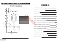
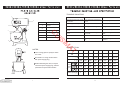
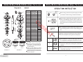
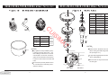
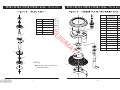
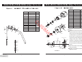
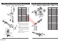
B20G/B20GA/B30G/B30GA
MIXER USER MANUAL
AT
IM
IS
U
C
AT
IM
IS
U
C
INDEX
PARTS CATALOG OVERVIEW
FIGURE 1 TRANSMISSION CASE
1
2
red
blue
12 bgreen
K
K3
10
C
FIGURE 3 GEAR AXLE
yellow
K0-ELECTROMAGNETIC SWITCH
M
5
K1-SAFETY COVERING SWITCH
U
K2
FIGURE 5 MOTOR UNIT
K2-FLUCTUATE SAFETY SWITCH
9
8
K1
red
yellow
K3-OVERLOAD PROTECTION SWITCH
K-SWITCH
C-CAPACITOR
red
M-MOTOR
FIGURE 7 MACHINE SEAT, STANDAND HANDWHEELTYPE BOWL LIFTER UINT
AT
K0
FIGURE 6 FORK AND SPEED SHAFT
IM
6
IS
red
red
FIGURE 4 GEAR AXLE I
C
red
7
FIGURE 2 AXLE
11
red
3
13 bgreen
FIGURE 8 HANDGRIP TYPE BOWL LIFTER UNIT
4
blue
FIGURE 8 TURNING PLATE AND MIXING AXLE
FIGURE 9 STANDARD ACCESSORIES
14
blue
OPERATION INSTRUCTION
15
blue
WARNING AND SPECIALATTENTION
TROUBLE SHOOTING AND SPECIFICTION
ELECTRIC DIAGRAM
15
TROUBLE SHOOTING
1
Trouble
2
Item
3
4
5
Descviption
Re-cover
The axle can't work when operate
the machine.
Poor contact of the electrical equipment.
The mixing bowl out of position.
Moving direction is not correct.
Leak oil.
Sealing washer is damaged.
Change.
Check the plug.
1
cover
2
rear cover
3
ring
Defficult to move the bowl up and
down.
Slideway is rusted.
Clean the slideway and lubrication.
4
Mixing device
The motor is overheat and speed
down.
The voltage is not enough, or incorrect speed.
Check the voltage or use lower speed.
5
french
Noise and over heat.
Poor lubrication.
Add or change lubrication.
6
bowl
Mixer touch the bowl.
The mixing device or bowl deformed.
Repair or change the bowl or mixing device.
IS
U
C
6
Possible Causes
IM
SPECIFICTION
AT
NOTES:
Type
The no using pipe line sprays to wash
the mixer.
Wet hand in no using contact switch
with power supply plug.
While maintaining the mixer, must pull
out first the power supply plug, and from
profession the personnel maintains.
Mixer
B20G
L
Power Supply
Input Power
20
V
W
Mixing
Speed
r.p.m
Maxflour Capacity(kg)
1
B20G
20
110~ 220-240~ /380~
B20GA B20GA
20
20
110~ 220-240~ /380~
B30G
B30G
B30GA
B30GA
28
28
28
28
110~ 220-240~ /380~
110~ 220-240~ /380~
1100
1100
1100
1100
1500
1500
1500
1500
548
462
548
462
548
462
548
462
376
317
376
317
376
317
376
317
208
197
208
197
208
197
208
197
5
5
5
5
6
6
6
6
14
Item
1
1 DON'T USE WATER PIPE TO WASH THE MIXER DIRECTLY;
2 PLEASE PULL OFF THE PLUG BEFORE MAINTAINNING, AND MAKE IT
2
MAINTAINED BY PROFESSIONALS;
3 DON'T TOUCH THE SWITCHSAND PLUG WITH WET HAND;
4 IF BROKEN, PLEASE STOP USINGAT ONCE
5 THERE ISAGROUNDED NUT (SIGNED "
") IN THE MACHINE, PLEASE
9
3
11
4
C
RECOVER IT TO ORIGIN CONDITION, DON'T CANCELTHE GROUNDED LINE;
10
6 DON'T PUT HANDS INTO THE BOWL OR TOUCH THE MIXING DEVICES WH-
5
7 DON'TALLOW THE MINOR CLOSE TO THE MACHINE;
8 THE MACHINE SHOULD BE FIXED ON THE DRYWOODEN SPLINTAND WO9 IF THE ELECTRICALWIRE IS BROKEN, PLEASE CHANGE IT BY PROFECTIONALS.
8
7
AT
1 BEFORE USING , PLEASE CLEAN THE BOWLAND THE MIXING DEVICES CAR-
12
6
Qty
1
screw M6*45
1
2
cover
1
3
screw M5*8
4
4
cover
1
5
bearing 6201
2
6
screw M6*25
4
7
end cover
1
8
body
1
9
screw M5*8
3
10
cover
1
11
bearing 6003
1
12
rear cover
1
IM
RK IN SAFEAREA;
IS
U
EN WORKING;
Descviption
NOTES
EFULLY,AND THEN INSTALLTHE BOWL ONTO THE MACHINE CORRECTLY
AND TIGHTLY;
2 WHEN CHOOSING MIXING DEVICES, PLEASE REFER TO THE OPERATION MA-
cover (4)
NUALTO CHOSE THE CORRECT SPEED, OR IT WILL DESTORYTHE INSIDE SPARE PARTSAND SHORTEN THE USING LIFE OF THE MACHIE;
Machine at a factory hour have added to
note the superior quality lubricates the
grease, usually the circumstance bottom
can use for several years, but machine is
after maintaining, must replace the lubrication grease.
3 AFTER USING, PLEASE POWER OFF THE MACHINE,AND PUT THE BOWLAND
DEVICES IN THE SAFEAND CLEAN PLACEAFTER CLEANING;
4 KEEP ENVIROMENTARROUND THE MACHINE DRY
HEALTHAND SAFE.
cover (10)
Fill with the lubrication grease empress,
please the cover the tight noting the oil bore cover.
In order to keep safety, when using Mixing device I/II/III , Please pay attention to insert their
grooves which are from the handles into the spiral axle pin separately. Furthermore, rising the
bowl to the highest positon, so that the edge of the bowl is higher than Mixing device I/II/III
working position.
13
2
Item
20
Qty
Descviption
1
1
baffle
2
roller
3
spring
8
4
engager
1
5
gear ring
1
6
dividing ring
1
7
joint gear
1
8
bearing ring
1
9
joint
1
380V
10
1
16
11
5
12
17
4
15
14
7
9
Vertical sides of jaws must face
on another.
1
10
bearing ring
11
joint gear I
12
ring
1
13
bearing 6205
1
14
oil seal Pd30*45*10
1
15
sleeve
1
16
axle
1
17
key 6*14
1
18
key 5*35
2
19
key 6*30
1
20
bearing 6003
1
1
OFF
AT
8
Before testing, please take mixing device off first, in
order to avoid damage machine which is match moving direction. It's necessary to change the three-phase machine if the moving direction is not match with arrow.
IM
19
your machine and be sure ground wire is eliable.
IS
6
A
NOTES
RIGHT
FIGURE 2-1
WRONG
FIGURE 2-2
3
Before using, please check power supply if it match
U
18
C
3 2
13
4
8*16
110V
220V
230V
240V
Be sure to install correct position
(see Figure 2-1) and lubricate all
of the pins in the sleeve drive when reassembling.
Joint (9) must always be raised
and lowered smoothly. Be sure joint sleeve as shown in Figure 2-2.
Check oil seal (14), if serious oil leaks from drip cup.
B
C
For changing the speed: Please stop machine first
before change speed in order to aviod damage gear
box.
Mixing: according to the different mixing-material.
Choose the different mixing devices and speed.
A: Be suitable for mix and stir butter, eggs, and work with in high speed, working time is less than 15 minutes.
B. Be suitable for mix and stir stuffing and raw material,
and work in middle speed, working time is less than 20
minutes.
C: middle position is suitable for mixing dough,
working time is less than 30 minutes.Flour water quantity is 40%-50%.
12
5
Item
1
6
7
C
2
1
U
1
Mixing device I
1
2
Mixing device II
1
3
Mixing device III
1
4
bowl
1
9
Any agitator is easily installed by simp-
1
2
gear axle
1
3
key 5*11
1
4
key 5*11
1
5
gear
1
6
stop ring
1
7
gear
1
8
stop ring
1
9
bearing 6201
1
4
NOTES
At the center in the shaft unit. To the
above is the gear shaft and gear sh-
gear axle (2)
ly raising it onto the mixing axle, and
aft I (see figure 3-1 ).
then rotating it clockwise on the shaft
C-type stop ring(6/8) has to be fixed
gear axle I
until into place. To remove, raise the a-
when reassembling.
gitator on the shaft until it clears the locspiral
k and then rotate counter-clockwise and
Be sure that the keys are inserted
lower.
for each gear.
All of tools are precisely fitted to the bowl, rounded corners and easily remov-
axle
fork
eable for cleaning.
FIGURE 3-1
11
bearing 6201
3
AT
Qty
IM
Descviption
NOTES
4
8
IS
Item
Qty
1
3
2
Descviption
4
I
6
Item
1
Descviption
1
2
gear axle
1
3
key 5*14
1
4
gear
1
5
stop ring
1
6
bearing 6201
1
8
2
IS
U
3
AT
IM
3
10
4
4
11
12
13
5
NOTES
6
C-type stop ring(5) has to be fixed
5-1
when reassembling.
14
5-2
5
10
Qty
screw M6*25
6
2
turning plate
1
3
ring
1
4
nut M18
1
5-1
safety net(locomotion)
1
5-2
safety net(immobility)
1
6
inner gear
1
7
screw M8*15
1
8
plantaty gear
1
9
bearing 6203
1
10
bearing 6204
1
11
oil seal Pd25*50*10
1
12
key 5*18
1
13
Mixing axle
1
14
Pin
1
9
1
C
bearing 6201
Descviption
1
Qty
1
2
Item
7
Item
Item
11
8
2
cottor pin 3*30
1
3
nut M10
3
4
flat washer
2
5
compression spring
1
7
6
little knot
1
7
lifting handle bracket
1
8
flat washer
9
flange knot
4
6
2
1
3
1
1
10
screw M6*25
11
key 5*20
1
12
bowl lift handle
1
1
stop ring
1
2
spiral
1
3
oil seal
1
4
bearing 6203
1
5
key 4*22
1
6
axle
1
7
rotor
1
8
switch
1
9
switch plastic
1
10
bearing 6203
1
11
bearing cover
1
12
fan
1
NOTES
12
If the motor does not work, first verify the power source and conn-
8
12
Qty
1
5
AT
1
10
1
IM
6
lifting bar
IS
2
1
U
9
Qty
C
7
Descviption
Descviption
11
ection. Next, check for damaged
10
or faulty wiring or connections ins-
9
ide the mixer. A noworking motor
bearing cover (11)
rotor (7)
fan (12)
may be the result of inappropriate
voltage, broken wires, a defective
capacitor, or a defective centrifugal
3
spiral(2)
governor. Motor damage may also
4
be caused by bowl overload during
mixing.
5
Motor set includes motor axle(6),
oil seal (3)
4
rotor(7) and stator.
bearing 6203 (4)
switch (8)
switch plastic (9)
3
Figure 5-1 is component system
diagrams of motor.
3
FIGURE 5-1
9
6
1
2
Item
3
1
4
nut
1
3
spring
1
4
shaft
1
5
fork
1
1
eccentricity knot
1
8
steel ball
9
speed spring
2
9
shaft
1
3
slide
1
4
plate
1
5
gear
1
6
capacitor board
capacitor 200uF
1
3
9
nut M10
3
10
spring
1
11
spiral
1
12
french support
1
13
handwheel
1
14
nut M10
1
15
handle
1
16
handle screw
1
17
machine seat
1
1
6
1
5
1
4
AT
3
9
18
safefy covering switch
1
10
19
fluctuate safety switch
1
20
overload protection switch
1
the proper number on the shift selector. Stop the mixer befor making any
speed changes.
Apply sealant to the shift selector as-
15
sembly, and install it .
16
11
12
13
7
stand
8
17
the pointer of the shifter handle with
FIGURE6-1
2
2
Speed selection is made by aligning
speed block (10)
1
3
peeds.
fork (5)
arm
1
reliability. It features three mixing s-
copper (8)
1
1
anism is designed for simplicity and
10
Qty
support seat
The speed selector / shifting mech11
Descviption
7
NOTES
12
1
IM
8
7
screw M5*10
8
20
IS
12
3
speed block
7
18
U
11
6
C
pin 3*20
7
10
4
Item
19
1
axle
2
6
5
Qty
Descviption
14
8