1
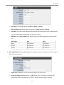
Table of Contents
Chapter 1. System Overview .......................................................................................................................... 1 1.1 Introduction of TEW‐455APBO……………………………………………………………………………………………………….1 1.2 System Concept………………………………………………………………………………………………………………………………2 1.3 Applications in Wireless Network……………………………………………………………………………………………………3 1.4 Product Benefit……………………………………………………………………………………………………………………………….7 1.5 Specification……………………………………………………………………………………………………………………………………8 1.6 Wireless Performance Considerations……………………………………………………………………………………….11 Chapter 2. Basic Installation…………………………………………………………………………………………………………………….12 2.1 Hardware Installation……………………………………………………………………………………………………………………12 2.1.1 Package Contents…………………………………………………………………………………………………………………..12 2.1.2 Panel Function Descriptions…………………………………………………………………………………………………..12 2.2 Web Management Interface Instructions………………………………………………………………………………………13 Chapter 3. AP Mode Configuration………………………………………………………………………………………………………….16 3.1 External Network Connection……………………………………………………………………………………………………….16 3.1.1 Network Requirement…………………………………………………………………………………………………………..16 3.1.2 Configure LAN IP……………………………………………………………………………………………………………………17 3.2 Wireless LAN Network Creation……………………………………………………………………………………………………19 3.2.1 Wireless General Setup………………………………………………………………………………………………………….19 3.2.2 Wireless Advanced Setup……………………………………………………………………………………………………….21 3.2.3 Create Virtual AP (VAP)…………………………………………………………………………………………………………..25 3.2.3.1 Virtual AP Overview ………………………………………………………………………………………………………..25 3.2.3.2 Virtual AP Setup………………………………………………………………………………………………………………27 3.2.4 MAC Filter Setup…………………………………………………………………………………………………………………….34 3.3 Wireless Network Expansion………………………………………………………………………………………………………….35 3.4 System Management…………………………………………………………………………………………………………………….38 3.4.1 Configure Management…………………………………………………………………………………………………………38 3.4.2 Configure System Time………………………………………………………………………………………………………….41 3.4.3 Configure UPnP………………………………………………………………………………………………………………………42 3.4.4 Configure SNMP Setup……………………………………………………………………………………………………………43 3.4.5 Backup / Restore and Reset to Factory……………………………………………………………………………………45 3.4.6 Firmware Upgrade………………………………………………………………………………………………………………….46 3.4.7 Network Utility………………………………………………………………………………………………………………………..47 3.4.8 Reboot…………………………………………………………………………………………………………………………………….48 3.5 System Status………………………………………………………………………………………………………………………………….49 3.5.1 System Overview…………………………………………………………………………………………………………………….49 3.5.2 Associated Clients Status…………………………………………………………………………………………………………51 3.5.3 WDS Link Status………………………………………………………………………………………………………………………52 3.5.4 Extra Information……………………………………………………………………………………………………………………53 3.5.5 Event Log………………………………………………………………………………………………………………………………..55 Chapter 4. WDS Mode Configuration………………………………………………………………………………………………………..56 4.1 External Network Connection…………………………………………………………………………………………………………56 4.1.1 Network Requirement…………………………………………………………………………………………………………….56 4.1.2 WDS Setup………………………………………………………………………………………………………………………………57 4.2 System Status………………………………………………………………………………………………………………………………….59 4.2.1 System Overview…………………………………………………………………………………………………………………….59 4.2.2 WDS Link Status………………………………………………………………………………………………………………………61 Chapter 5. CPE Mode Configuration………………………………………………………………………………………………………….62 5.1 External Network Connection…………………………………………………………………………………………………………62 5.1.1 Network Requirement…………………………………………………………………………………………………………….62 5.1.2 Configure WAN Setup……………………………………………………………………………………………………………..63 5.1.3 Configure DDNS Setup…………………………………………………………………………………………………………….66 5.1.4 Site Survey……………………………………………………………………………………………………………………………..67 5.2 Access Control List…………………………………………………………………………………………………………………………68 5.2.1 IP Filter Setup…………………………………………………………………………………………………………………………68 5.2.2 MAC Filter Setup…………………………………………………………………………………………………………………….70 5.3 Resource Sharing……………………………………………………………………………………………………………………………71 5.3.1 DMZ……………………………………………………………………………………………………………………………………….71 5.3.2 Virtual Server (Port Forwarding)…………………………………………………………………………………………….72 5.4 System Status…………………………………………………………………………………………………………………………………74 5.4.1 System Overview……………………………………………………………………………………………………………………74 5.4.2 DHCP Clients………………………………………………………………………………………………………………………….78 6. Command Line Interface(CLI)………………………………………………………………………………………………………………79 6.1 Accessing the CLI with Telnet…………………………………………………………………………………………………………79 6.2 Accessing the CLI with SSH Utility…………………………………………………………………………………………………..80 6.3 Using the CLI………………………………………………………………………………………………………………………………….81 Appendix A. WEB GUI Valid Characters………………………………………………………………………………………………….85 Appendix B. Network manager Privileges………………………………………………………………………………………………89 Appendix C. Enabling UPnP in Windows XP……………………………………………………………………………………………90 Limited Warranty…………………………………………………………………………………………………………………………………….92 User Manual
TEW‐455APBO High Power Wireless Outdoor PoE Access Point Chapter 1. System Overview 1.1 Introduction of TEW‐455APBO The 802.11 b/g compliant TEW‐455APDO is an outdoor wireless device that can be used for five different purposes in three different modes. In the AP mode, it can be deployed either as traditional fixed wireless Access Point (AP), or combination of AP and WDS(AP+WDS). In the WDS mode, it’s only used to expand or bridge Ethernet networks and deployed as a main base, relay based or remote base station. In the CPE mode, it connects to Wireless Internet Service Provider’s (WISP) outdoor network via wireless WAN gateway to access to Internet. The die‐cast sealed TEW‐455APDO is compact in size and compliant with IP66/IP67 weatherproof standard. It comes with a mounting kit to mount on pole or wall. It is suitable for both indoor and outdoor usage with its adjustable output power. 1. Access Point : It can be deployed as a traditional fixed wireless Access Point 2. Repeater: To expand wireless service by repeating prior AP 3. WDS : It can be used to expand Ethernet network via wireless WDS Link 4. AP+WDS: Not only to extend Ethernet network, but also provide wireless access to the expanded network 5. CPE (Customer Premises Equipment): It is a wireless gateway with NAT and DHCP Server functions to connects to Wireless Internet Service Provider's (WISP) 1 User Manual
TEW‐455APBO High Power Wireless Outdoor PoE Access Point 1.2 System Concept The TEW‐455APDO is not only designed and used as traditional outdoor AP, but also with rich features tailored for WISP applications. The two‐level management capability and access control ease WISP and owners to maintain and manage wireless network in a more controllable fashion. Main applications are listed as follows with illustration:
Wireless CPE for Multi Dwelling Unit/Multi Tenant Unit (MDU/MTU) complexes including apartments, dormitories, and office complexes.
Outdoor Access Point for school campuses, enterprise campuses, or manufacture plants.
Indoor Access Point for hotels, factories, or warehouses where industrial grade devices are preferred.
Public hotspot operation for café, parks, convention centers, shopping malls, or airports.
Wireless coverage for indoor and outdoor grounds in private resorts, home yards, or golf course communities. 2 User Manual
TEW‐455APBO High Power Wireless Outdoor PoE Access Point 1.3 Applications in Wireless Network TEW455APBO is a multiple mode system which can be configured either as a wireless gateway or an access point as desired. It also can be used WDS link for Ethernet network expansion. This section depicts different applications on AP Mode, WDS Mode, and CPE Mode.
Configuration in AP Mode (including Access Point + WDS) An access point can be either a main, relay or remote base station. A main base station is typically connected to a wired network via the Ethernet port. A relay base station relays data between main base stations and relay stations or remote base stations with clients. A remote base station is the end point to accept connections from wireless clients and pass data upwards to a network wirelessly. Î
Example 1 : Access Point without WDS 9
Î
It can be deployed as a tradition fixed wireless Access Point Example 2 : Access Point with WDS 9
It can be deployed as a tradition fixed wireless Access Point and provides WDS link to expand network 3 User Manual
TEW‐455APBO High Power Wireless Outdoor PoE Access Point
Configuration in WDS Mode (Pure WDS) An access point can be either a main, relay or remote base station. A main base station is typically connected to a wired network via the Ethernet port. A relay base station relays data between main base stations and relay stations or remote base stations with clients. A remote base station is the end point to accept connections from wireless clients and pass data upwards to a network wirelessly. In this mode, it can support single or multiple WDS links and no wireless clients can associate with it though. Î
Example 1 : Point‐to‐Point 4 User Manual
TEW‐455APBO High Power Wireless Outdoor PoE Access Point Î
Example 2 : Point‐to‐Multi‐Point Î
Example 3 : Multi‐Point Repeating bridge 5 User Manual
TEW‐455APBO High Power Wireless Outdoor PoE Access Point
Configuration in CPE Mode It can be used as an Outdoor Customer Premises Equipment (CPE) to receive wireless signal over last mile application, helping WISPs deliver wireless broadband Internet service to residents and business customers. In the CPE mode, TEW‐455APBO is a gateway enabled with NAT and DHCP Server functions. The wired clients connected to TEW‐455APBO are in different subnet from those connected to Main Base Station, and, in CPE mode, it does not accept wireless association from wireless clients. 6 User Manual
TEW‐455APBO High Power Wireless Outdoor PoE Access Point 1.4 Product Benefit
High Adjustable Output Power up to 27dBm (FCC version)/6dBm (EU version)
Topology : Point to Point ; Point to Multi Point
Operation Modes : Î
Access Point Mode : Pure Access Point Function and Access Point /Bridge(WDS) Function Î
WDS Mode Î
CPE Mode (Router Client )
Security with WEP, WPA/WPA2‐PSK, and WPA/WPA2‐RADIUS
Over load current protection
Integrated Power over Ethernet (PoE)
8 Multiple B‐SSID capability
Business‐class security and central management
IP66/IP67 Weather‐Proof Housing
VLAN tag over WDS
Client Isolation through Layer 2 VLAN technology TEW‐455APBO is the point of connection to Wireless Outdoor Network for service provider deploying last mile services to business or residential broadband subscribers.. Network administrators can create multiple subscriber service tier using per‐subscriber rate limiting features, and manage centrally. TEW‐455APBO outdoor bridge utilizes adjustable output Tx Power to connect to the Wi‐Fi mesh or WDS infrastructure and provides the subscriber with an Ethernet connection for a local access. TEW‐455APBO supports three operational modes, the AP mode, the WDS mode and the CPE mode, respectively with built‐in remote management features. 7 User Manual
TEW‐455APBO High Power Wireless Outdoor PoE Access Point 1.5 Specification
Wireless Architecture Mode Î
AP Mode 9
9
Pure AP Mode •
It can be deployed as a tradition fixed wireless Access Point •
It allow wireless clients or Stations(STA) to access AP/WDS Mode •
This enables the wireless interconnection of Access Point in an IEEE802.11 network .and accept wireless clients at the same time Î
WDS Mode 9
This enables the wireless interconnection of Access Point in an IEEE802.11 network. 9
It allows a wireless network to be expanded using multiple access point without the need for a wired backbone to link them. 9
Î
It can’t allow wireless clients or Stations (STA) to associate. CPE Mode 9
Wi‐Fi connection as WAN , in CPE mode , the device run as DHCP server to assign IP address to clients out of a private IP address pool behind a NAT
Networking Î
Support Static IP, Dynamic IP(DHCP Client) and PPPoE on Wi‐Fi WAN Connection Î
Support PPTP/L2TP/IP Sec Pass Through Î
PPPoE Reconnect – Always On , On demand, Manual Î
MAC Cloning Î
DHCP Server Î
802.3 Bridging Î
Masquerading (NAT) Î
Proxy DNS Î
Dynamic DNS Î
NTP Client Î
Virtual DMZ 8 User Manual
TEW‐455APBO High Power Wireless Outdoor PoE Access Point Î
Virtual Server (IP / Port Forwarding) Î
Support MAC Filter (max 20 entries) Î
Support IP Filter (max 20 entries) Î
Bandwidth traffic Shaping
Wireless Feature Î
Transmission power control : 9 Levels (max 27dBm for FCC, 6dBm for CE) Î
Channel selection : Manual or Auto Î
No of associated clients per AP : 32 Î
Setting for max no associated clients : Yes Î
No. of ESSID (Virtual AP) : 8 Î
No. of Max. WDS setting : 8 Î
Preamble setting : Short/ Long Î
Setting for 802.11b/g mix, 802.11b only or 802.11g only Î
Setting for transmission speed Î
Dynamic Wireless re‐transmission Î
IEEE802.11f IAPP (Inter Access Point Protocol), hand over users to another AP Î
IEEE 802.11i Preauth (PMKSA Cache ) Î
IEEE 802.11h ‐Transmission Power Control Î
IEEE 802.11d ‐Multi country roaming
Authentication/ Encryption (Wireless Security) Î
Layer 2 User Isolation Î
Blocks client to client discovery within a specified VLAN Î
WEP 64/ 128/ 152 Bits Î
EAP‐TLS + Dynamic WEP Î
EAP‐TTLS + Dynamic WEP Î
PEAP/ MS‐PEAP + Dynamic WEP Î
WPA (PSK +TKIP) Î
WPA (802.1x certification + TKIP) 9 User Manual
TEW‐455APBO High Power Wireless Outdoor PoE Access Point Î
802.11i WPA2 (PSK + CCMP/ AES) Î
802.11i WPA2 (802.1x certification + CCMP/ AES) Î
Setting for TKIP/ CCMP/ AES key’s refreshing period Î
Hidden ESSID support Î
Setting for “ Deny ANY “ connection request Î
MAC Address filtering (MAC ACL) Î
No. of registered RADIUS servers : 2 Î
VLAN assignment on BSSID Î
Support VLAN tag over WDS
Quality of Service Î
DiffServ/ TOS Î
IEEE802.1p/ COS Î
IEEE 802.1Q Tag VLAN priority control Î
IEEE802.11e WMM
System Administration Î
Intuitive Web Management Interface Î
Password Protected Access Î
Firmware upgrade via Web Î
Reset to Factory Defaults Î
Profiles Configuration Backup and Restore Î
Remote Link Test Î
Full Statistics and Status Reporting Î
SNMP Traps to a list of IP Address Î
NTP Time Synchronization Î
Even Log Î
Support SNMP v1,v2c, v3 Î
Support MIB II Î
CLI access via Telnet and SSH 10 User Manual
TEW‐455APBO High Power Wireless Outdoor PoE Access Point Î
Administrative Access : HTTP/ HTTPS Î
UPnP (Universal Plug and Play) 1.6 Wireless Performance Considerations There are a number of factors that can impact the range of wireless devices. 1. Adjust your wireless devices so that the signal is traveling in a straight path, rather than at an angle. The more material the signal has to pass through the more signal you will lose. 2. Keep the number of obstructions to a minimum. Each obstruction can reduce the range of a wireless device. Position the wireless devices in a manner that will minimize the amount of obstructions between them. 3. Building materials can have a large impact on your wireless signal. In an indoor environment, try to position the wireless devices so that the signal passes through less dense material such as dry wall. Dense materials like metal, solid wood, glass or even furniture may block or degrade the signal. 4. Antenna orientation can also have a large impact on your wireless signal. Use the wireless adapter’s site survey tool to determine the best antenna orientation for your wireless devices. 5. Interference from devices that produce RF (radio frequency) noise can also impact your signal. Position your wireless devices away from anything that generates RF noise, such as microwaves, radios and baby monitors. 6. Any device operating on the 2.4GHz frequency will cause interference. Devices such as 2.4GHz cordless phones or other wireless remotes operating on the 2.4GHz frequency can potentially drop the wireless signal. Although the phone may not be in use, the base can still transmit wireless signal. Move the phone’s base station as far away as possible from your wireless devices. If you are still experiencing low or no signal consider repositioning the wireless devices or installing additional access points. The use of higher gain antennas may also provide the necessary coverage depending on the environment. 11 User Manual
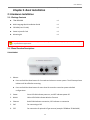
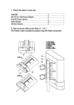
TEW‐455APBO High Power Wireless Outdoor PoE Access Point Chapter 2. Basic Installation 2.1 Hardware Installation 2.1.1 Package Contents
TEW‐455APBO x 1
Multi‐Language Quick Installation Guide x 1
CD‐ROM (User’s Guide) x 1
Power Injector & Cord x 1
Mounting Kit x 1 It is highly recommended to use all the supplies in the package instead of substituting any components by other suppliers to guarantee best performance. 2.1.2 Panel Function Descriptions TEW‐455APBO 1. Reboot: Î
Press and hold the Reset button for 2 seconds and release to restart system. The LED except Power indicator will be off before restarting. Î
Press and hold the Reset button for more than 10 seconds to reset the system to default configurations. 2. Power: Green LED ON indicates power on, and OFF indicates power off. 3. WLAN: Yellow LED FLASH indicates Wireless Transmit. 4. Ethernet Red LED ON indicates connection, OFF indicates no connection 5. PoE: For connecting to PSE 6. EXT: For connection of optional N‐Type antenna (example: TRENDnet TEW‐AO19D) 12 User Manual
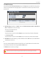
TEW‐455APBO High Power Wireless Outdoor PoE Access Point 2.2 Web Management Interface Instructions TEW‐455APBO supports web‐based configuration. Upon the completion of hardware installation, TEW‐
455APBO can be configured through a PC/NB by using its web browser such as Internet Explorer version 6.0 or higher.
Default IP Address : 192.168.10.100
Default Subnet Mask : 255.255.255.0
Default User Name and Password: The default user name and password for both root manager account and admin manager account are as follows: Mode CPE Mode AP Mode WDS Mode Management Account Admin Account Status Account Admin Account Admin Account
User Name root admin root root Password root admin root root Step
IP Segment Set‐up for Administrator's PC/NB Set the IP segment of the administrator's computer to be in the same range as TEW‐455APBO for accessing the system. Do not duplicate the IP Address used here with IP Address of TEW‐455APBO or any other device within the network Example of Segment: The valid range is 1 ~ 254 and 192.168.10.100 shall be avoided because it is already assigned to TEW‐
455APBO and 192.168.10.10 is used in the example below. Î
IP Address : 192.168.10.10 Î
IP Netmask : 255.255.255.0 13 User Manual
TEW‐455APBO High Power Wireless Outdoor PoE Access Point
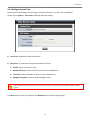
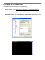
Launch Web Browser Launch a web browser to access the web management interface of system by entering the default IP Address, http://192.168.10.100, in the URL field, and then press Enter.
System Login The network manager Login Page then appears. Enter “root” as User name and “root” as Password, and then click OK to login to the system; the root manager account is used as an example here. 14 User Manual
TEW‐455APBO High Power Wireless Outdoor PoE Access Point
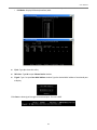
Login Success
System Overview page will appear after successful login.
15 User Manual
TEW‐455APBO High Power Wireless Outdoor PoE Access Point Chapter 3. AP Mode Configuration When AP mode is chosen, the system can be configured as an Access Point. This section provides detailed explanation for users to configure in the AP mode with help of illustrations. In the AP mode, functions listed in the table below are also available from the Web‐based GUI interface. Option Functions System Wireless Administrator Status Operating Mode General Settings Management System Overview LAN Advanced Settings Profiles Settings Clients Time Server Virtual AP Firmware Upgrade WDS Status SNMP WDS Setup Network Utility Extra Info UPNP Reboot Table 3‐1: AP Mode Functions Event Log 3.1 External Network Connection 3.1.1 Network Requirement Normally, TEW‐455APBO connects to a wired LAN and provides a wireless connection point to associate with wireless client as shown in Figure 3‐1. Then, Wireless clients could access to LAN or Internet by associating themselves with TEW‐455APBO set in AP mode. Figure 3‐1 Access Point on a Wired LAN Configuration 16 User Manual
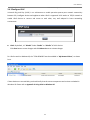
TEW‐455APBO High Power Wireless Outdoor PoE Access Point 3.1.2 Configure LAN IP Here are the instructions to setup the local IP Address and Netmask. Please click on System Æ LAN and follow the below setting.
Mode: Check either “Static IP” or “Dynamic IP” button as desired to set up the system IP of LAN port. Î
Î
Static IP: The administrator can manually setup the LAN IP address when static IP is preferred. 9
IP Address: The IP address of the LAN port; default IP address is 192.168.10.100 9
IP Netmask: The Subnet mask of the LAN port; default Netmask is 255.255.255.0 9
IP Gateway: The default gateway of the LAN port; default Gateway is 192.168.10.1 Dynamic IP: This configuration type is applicable when the TEW‐455APBO is connected to a network with presence of a DHCP server. All related IP information will be provided by the DHCP server automatically. 9
Hostname : The Hostname of the LAN port 17 User Manual
TEW‐455APBO High Power Wireless Outdoor PoE Access Point
DNS: Check either “No Default DNS Server” or “Specify DNS Server IP” button as desired to set up the system DNS.
Î
Primary: The IP address of the primary DNS server. Î
Secondary: The IP address of the secondary DNS server. 802.1d Spanning Tree The spanning tree network protocol provides a loop free topology for a bridged LAN between LAN interface and 8 WDS interfaces from WDS0 to WDS7. The Spanning Tree Protocol, which is also referred to as STP, is defined in the IEEE Standard 802.1d. Click Save button to save your changes. Click Reboot button to activate your changes. 18 User Manual
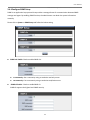
TEW‐455APBO High Power Wireless Outdoor PoE Access Point 3.2 Wireless LAN Network Creation The network manager can configure related wireless settings, General Settings, Advanced Settings, Virtual AP (VAP) Setting, Security Settings, and Access Control Settings. 3.2.1 Wireless General Setup The administrator can change the data transmission, channel and output power settings for the system. Please click on Wireless ‐> General Setup and follow the below setting.
MAC address: The MAC address of the Wireless interface is displayed here.
Band Mode: Select an appropriate wireless band; bands available are 801.11b, 802.11g and 802.11b+802.11g.
Transmit Rate Control: Select the desired rate from the drop‐down list; the options are auto or ranging from 1 to 54Mbps for the 802.11g and 802.11b/g modes, or 1 to 11Mbps for the 802.11b mode.
Domain: Select the desired domain from the drop‐down list; the options are FCC and ETSI.
Channel: The channel range will be changed by selecting different domain. The channels range from 1 to 11 for the FCC domain, or 1 to 13 for the ETSI domain. 19 User Manual
TEW‐455APBO High Power Wireless Outdoor PoE Access Point
Tx Power: You can adjust the output power of the system to get the appropriate coverage for your wireless network. Select the LEVEL 1 to LEVEL 9 that you need for your environment. If you are not sure from which setting to choose, then use the default LEVEL 9 setting. Output Power Chart FCC Domain
ETSI Domain
Level 1 3dBm
1dBm
Level 2 6dBm
2dBm
Level 3 9dBm
3dBm
Level 4 12dBm
4dBm
Level 5 15dBm
5dBm
Level 6 18dBm
6dBm
Level 7 21dBm
6dBm
Level 8 24dBm
6dBm
Level 9 27dBm
6dBm
*The power value might be ± 1dBm
Super G: Click Enable button to activate super G and Disable to deactivate super G. Click Save button to save your changes. Click Reboot button to activate your changes. The items in this page are for AP's RF general settings and will be applied to all VAPs. 20 User Manual
TEW‐455APBO High Power Wireless Outdoor PoE Access Point 3.2.2 Wireless Advanced Setup To achieve optimal wireless performance, it is necessary to tweak advance setting per requirements properly, not necessary higher the better or lower. The administrator can change the RTS threshold and fragmentation threshold settings for the system. Please click on Wireless ‐> Advanced Setup and follow the below setting.
Slot Time : Slot time is in the range of 1~1489 and set in unit of microsecond. The default value is 20 microsecond. Slot time is the amount of time a device waits after a collision before retransmitting a packet. Reducing the slot time decreases the overall back‐off, which increases throughput. Back‐off, which is a multiple of the slot time, is the random length of time a station waits before sending a packet on the LAN. For a sender and receiver own right of the channel the shorter slot time help manage shorter wait time to re‐transmit from collision because of hidden wireless clients or other causes. When collision sources can be removed sooner and other senders attempting to send are listening the channel(CSMA/CA) the owner of the channel should continue ownership and finish their transmission and release the channel. Then, following ownership of the channel will be sooner for the new pair due to shorter slot time. However, when long duration of existing collision sources and shorter slot time exist the owners might experience subsequent collisions. When adjustment to longer slot time can’t improve performance then RTS/CTS could supplement and help improve performance. 21 User Manual
TEW‐455APBO High Power Wireless Outdoor PoE Access Point
ACK Timeout: ACK timeout is in the range of 1~372 and set in unit of microsecond. The default value is 48 microsecond. All data transmission in 802.11b/g request an “Acknowledgement” (ACK) send by receiving radio. The transmitter will resend the original packet if correspondent ACK failed to arrive within specific time interval, also refer to as “ACK Timeout”. ACK Timeout is adjustable due to the fact that distance between two radio links may vary in different deployment. ACK Timeout makes significant influence in performance of long distance radio link. If ACK Timeout is set too short, transmitter will start to “Resend” packet before ACK is received, and throughputs become low due to excessively high re‐transmission. ACK Timeout is best determined by distance between the radios, data rate of average environment. The Timeout value is calculated based on round‐trip time of packet with a little tolerance, So, if experiencing re‐transmissions or poor performance the ACK Timeout could be made longer to accommodate. RTS/CTS Adjustment of RTS Threshold can be done to turn on RTS. CTS Timeout will take effect only when RTS is turned on. Unlike wired Ethernet, radio transmission may begin with a RTS (Request to Send) frame, and receiver responds with a CTS (Clear to Send) frame. The RTS/CTS mechanism is called Channel Cleaning, all stations that received CTS will back off for certain period of time, multiple of the slot time. Each CTS packet has a NAV (Network Allocation Vector) number n, the channel is reserved for sender and receiver for additional n‐millisecond. The NAV guarantees the channel is free of interference in next n‐
millisecond. The last packet of ACK will set NAV to zero, indicated that connection is done and free the channel to others.
CTS Timeout: CTS Timeout is in the range of 1~744 and set in unit of microsecond. The default value is 48 microsecond. CTS Timeout will take effect only when RTS is turned on. Adjustment of RTS Threshold can be done to turn on RTS. When hidden wireless stations are present in the wireless network RTS can be considered to turn on to minimize collisions and increase performance. Ensure CTS timeout is long enough to avoid frequent re‐transmission of RTS. Slot Time and ACK/CTS Timeout settings are for long distance links. It is important to tweak settings to achieve the optimal result based on requirement. The device’s default settings should be sufficient for most applications. 22 User Manual
TEW‐455APBO High Power Wireless Outdoor PoE Access Point
RSSI Threshold: RSSI Threshold is in the range of ‐128~127.The default value is 24. RSSI is defined as Received Signal Strength Indication, when the received signal strength from peer is below this threshold, the peer will be consider as disconnected. Set the threshold higher will make roaming happen earlier, set lower will allow weak signal peer to connect. In normal condition, the longer the distance, the lower the signal strength between peers. You could consider lowering RSSI to increase the wireless coverage. Increase the RSSI Threshold to have a more stable, but smaller coverage area.
Beacon Interval: Beacon Interval is in the range of 1~5000 and set in unit of millisecond. The default value is 100 msec. Access Point (AP) in IEEE 802.11 will send out a special approximated 50‐byte frame, called “Beacon”. Beacon is broadcast to all the stations, provides the basic information of AP such as SSID, channel, encryption keys, signal strength, time stamp, support data rate. All the radio stations received beacon recognizes the existence of such AP, and may proceed next actions if the information from AP matches the requirement. Beacon is sent on a periodic basis, the time interval can be adjusted. By increasing the beacon interval, you can reduce the number of beacons and associated overhead, but that will likely delay the association and roaming process because stations scanning for available access points may miss the beacons. You can decrease the beacon interval, which increases the rate of beacons. This will make the association and roaming process very responsive; however, the network will incur additional overhead and throughput will go down.
DTIM Interval: The DTIM interval is in the range of 1~15. The default is 15. DTIM is defined as Delivery Traffic Indication Message. It is used to notify the wireless stations, which support power saving mode, when to wake up to receive multicast frame. DTIM is necessary and critical in wireless environment as a mechanism to fulfill power‐saving synchronization. A DTIM interval is a count of the number of beacon frames that must occur before the access point sends the buffered multicast frames. For instance, if DTIM Interval is set to 3, then the Wi‐Fi clients will expect to receive a multicast frame after receiving three Beacon frame. The higher DTIM interval will help power saving and possibly decrease wireless throughput in multicast applications.
Fragment Threshold: The Fragment Threshold is in the range of 256~2346 byte. The default is 2346 byte. Each Wi‐Fi packet can be divided into smaller packets, marked with a sequential fragment number and re‐
assemble in the receiving ends. The purpose is to make a short frame, instead of long frame, transmitting by radio in a heavy noisy environment. Because of sending smaller frames, corruptions are much less likely 23 User Manual
TEW‐455APBO High Power Wireless Outdoor PoE Access Point to occur. The pros is obvious, the cons is the overhead for transmission. So, in a clean environment, higher fragment threshold can be an option to increase throughput. Fragmentation will be triggered by setting the Fragment Threshold, usually in Byte‐length. Only when the frame size is over the Threshold, fragmentation will take place automatically.
RTS Threshold: RTS Threshold is in the range of 1~2346 byte. The default is 2346 byte. The main purpose of enabling RTS by changing RTS threshold is to reduce possible collisions due to hidden wireless clients. RTS in AP will be enabled automatically if the packet size is larger than the Threshold value. By default, RTS is disabled in a normal environment supports non‐jumbo frames.
Short Preamble: By default, it’s “Enable”. To Disable is to use Long 128‐bit Preamble Synchronization field. The preamble is used to signal "here is a train of data coming" to the receiver. The short preamble provides 72‐bit Synchronization field to improve WLAN transmission efficiency with less overhead.
Tx Burst: By default, it’s “Enable”. To Disable is to deactivate Tx Burst. With TX burst enabled, AP will send many packets in a burst, without collision detection and RTS/CTS for each packet. TX Burst have better throughput but cause interference with other APs using the same channel.
802.11g Protection Mode: By default, it’s “Enable”. To Disable is to deactivate 802.11g Protection Mode. Protection mode use RTS/CTS to prevent interference with other APs and 802.11b peers, and disabling it will save transmission time used by RTS/CTS. RTS/CTS threshold is effective only when 802.11g protection mode is made enable. Click Save button to save your changes. Click Reboot button to activate your changes. The items in this page are for AP's RF advanced settings and will be applied to all VAPs. 24 User Manual
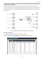
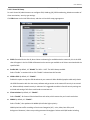
TEW‐455APBO High Power Wireless Outdoor PoE Access Point 3.2.3 Create Virtual AP (VAP) The TEW‐455APBO support broadcasting multiple SSIDs, allowing the creation of Virtual Access Points, partitioning a single physical access point into 8 logical access points, each of which can have a different set of security, VLAN tag(ID) and network settings. Figure 3‐2 shows multiple SSIDs with different security type and VLAN settings. Figure 3‐2 Multiple SSIDs with different Security Type and VLAN Tag 3.2.3.1 Virtual AP Overview The administrator can view all of the Virtual AP's settings via this page. Please click on Wireless ‐> Virtual AP Setup and the Virtual AP Overview Page appears. 25 User Manual
TEW‐455APBO High Power Wireless Outdoor PoE Access Point
VAP: Indicate the system's available Virtual AP
ESSID: Indicate the ESSID of the respective Virtual AP
Status: Indicate the Status of the respective Virtual AP. The VAP0 always On
Security Type: Indicate an used security type of the respective Virtual AP
MAC Filter: Indicate an used MAC filter of the respective Virtual AP
MAC Filter Setup: Click Setup button to configure Virtual AP's MAC filter.
VAP Edit: Click Edit button to configure Virtual AP's settings, including security type. 26 User Manual
TEW‐455APBO High Power Wireless Outdoor PoE Access Point 3.2.3.2 Virtual AP Setup For each Virtual AP, administrators can configure SSID, VLAN tag (ID), SSID broadcasting, Maximum number of client associations, security type settings. Click Edit button on the VAP Edit column, and then a Virtual AP setup page appears.
ESSID: Extended Service Set ID, when clients are browsing for available wireless networks, this is the SSID that will appear in the list. ESSID will determine the service type available to AP clients associated with the specified VAP.
Enable VAP: By default, it’s “Disable” for VAP1 ~ VAP7. The VAP0 always enabled. Select “Enable” to activate VAP or click “Disable” to deactivate this function
Hidden SSID: By default, it’s “Disable”. Enable this option to stop the SSID broadcast in your network. When disabled, people could easily obtain the SSID information with the site survey software and get access to the network if security is not turned on. When enabled, network security is enhanced. It’s suggested to enable it after AP security settings are archived and setting of AP clients could make to associate to it.
Client Isolation: By default, it’s “Disable”. Select “Enable”, all clients will be isolated from each other, which means they can’t reach each other.
WMM: By default, it’s “Disable”. Select “Enable”, then packets with WMM QoS will take higher priority. WMM prioritizes traffic according to four Access Categories (AC) ‐ voice, video, best effort, and background. However, it does not provide guaranteed throughput. Packets with QOS header including 27 User Manual
TEW‐455APBO High Power Wireless Outdoor PoE Access Point Diffserv/IP TOS and 802.1p will be mapped into 4 Access Categories of WMM, packets without QOS header will be assigned to Best Effort queue, see table below. 802.1p/IP TOS mapping to WMM: Queue Data Transmitted Clients to AP IP TOS 802.1P Priority AC_BK Background. 0x08 0x20 1, 2 AC_BE Best Effort 0, 3 AC_VI Video 0x28 0xa0 4, 5 Voice 0x30 0xe0 0x88 0xb8 6, 7 AC_VO
Priority Description High throughput. Bulk data that requires maximum throughput and is not time‐sensitive is sent to this queue (FTP data, for example). Medium throughput and delay. Most traditional IP data is sent to Medium this queue Minimum delay. Time‐sensitive video data is automatically sent High to this queue Low High Time‐sensitive data like VoIP and streaming media are automatically sent to this queue IAPP Support: By default, it’s “Disable”. Inter Access‐Point Protocol is designed to enforce unique association throughout an ESS(Extended Service Set) and to enforce secure exchange of station's security context between current access point (AP) and new AP during hand off period. IAPP supported only for WPA‐PSK/WPA2‐PSK, WPA‐Enterprise/WPA2‐Enterprise and 802.1X security type.
Maximum Clients: The default value is 32. You can enter the number of wireless clients that can associate to a particular SSID. When the number of client is set to 5, only 5 clients at most are allowed to connect to this VAP.
VLAN ID (Tag): By default, it’s selected “Disable”. This system supports tagged Virtual LAN (VLAN). A valid number of 0 to 4094 can be entered after it’s enabled. If your network utilize VLANs you could tie a VLAN ID to a specific SSID, and packets from/to wireless clients belonging to that SSID will be tagged with that VLAN ID. This enables security of wireless applications by applying VLAN ID.
Security Type: Options are “Disabled”, “WEP”, and “AES” from the drop‐down list. All devices need to have the same security setting to build WDS link. Î
Disable: Data are unencrypted during transmission when this option is selected. Î
WEP: Wired Equivalent Privacy (WEP) is a data encryption mechanism based on a 64‐bit, 128‐bit or 152‐bit shared key. 28 User Manual
TEW‐455APBO High Power Wireless Outdoor PoE Access Point 9
Key Length: The available options are 64 bits, 128 bits or 152 bits. 9
WEP auth Method: Enable the desired option among Open system and Shared. 9
Key Index: key index is used to designate the WEP key during data transmission. 4 different WEP keys can be entered at the same time, but only one is chosen. 9
WEP Key #: Enter HEX or ASCII format WEP key value; the system supports up to 4 sets of WEP keys. Key Length Hex ASCII 64‐bit 10 characters
5 characters 128‐bit 26 characters 13 characters 152‐bit 32 characters 16 characters Î
WPA‐PSK/WPA2‐PSK: WPA or WPA2 Algorithms enable the system to access the network by using the WPA‐PSK protected access. 9
Cipher Suite: By default, it is TKIP. Select either AES or TKIP cipher suites 9
Group Key Update Period: By default, it is 600 seconds. This time interval for rekeying GTK, broadcast/multicast encryption keys, in seconds. Entering the time‐length is required. 29 User Manual
TEW‐455APBO High Power Wireless Outdoor PoE Access Point 9
Master Key Update Period: By default, it is 83400 seconds. This time interval for rekeying GMK, master key to generate GTKs, in seconds. Enter the time‐length required. 9
Key Type: Select either ASCII or HEX format for the Pre‐shared Key. 9
Pre‐shared Key: Enter the pre‐shared key; the format shall go with the selected key type. Pre‐shared key can be entered with either a 256‐bit secret in 64 HEX digits format, or 8 to 63 ASCII characters. Î
WPA‐Enterprise/WPA2‐Enterprise: The RADIUS authentication and encryption will apply if either one is selected. 9
WPA General Settings : •
Cipher Suite: By default, it is TKIP. Select either AES or TKIP cipher suites •
Group Key Update Period: By default, it’s 600 seconds. This time interval for rekeying GTK, broadcast/multicast encryption keys, in seconds. Entering the time‐length is required. •
Master Key Update Period: By default, it’s 83400 seconds. This time interval for rekeying GMK, master key to generate GTKs, in seconds. Enter the time‐length required. •
EAP Reauth Period: By default, it’s 3600 seconds; 0 second is to disable EAP Re‐
authentication. 9
Main and secondary Authentication RADIUS Server Settings : 30 User Manual
TEW‐455APBO High Power Wireless Outdoor PoE Access Point 9
•
Authentication Server: Enter the IP address of the Authentication RADIUS server.
•
Port: By default, it’s 1812. The port number used to communicate with RADIUS server.
•
Shared secret: A secret key used between system and RADIUS server. Supports 1 to 64 characters.
•
Accounting Server: Enable or Disable accounting features in RADIUS server.
Main or Secondary Accounting RADIUS Server Settings :
•
Accounting Server: Enter the IP address of the Accounting RADIUS server.
•
Port: By default, it’s 1813. The port number used to communicate with RADIUS server.
•
Shared Secret: A secret key used between system and Accounting RADIUS server. Supports 1 to 64
characters.
Î
WEP 802.1X: When WEP 802.1x Authentication is enabled, please refer to the following Dynamic WEP and RADIUS settings to complete configuration. 9
Dynamic WEP Settings : 31 User Manual
TEW‐455APBO High Power Wireless Outdoor PoE Access Point •
WEP Key length: The available options are 64 bits or 128 bits. The system will automatically generate WEP encryption keys. •
WEP Key Update Period: By default, it’s 300 seconds; 0 not to rekey. •
EAP Reauth Period: By default, it’s 3600 seconds; 0 second is to disable EAP Re‐
authentication. 9
Main and Secondary Authentication RADIUS Server Settings : •
Authentication Server: Enter the IP address of the Authentication RADIUS server. •
Port: By default, it’s 1812. The port number used to communicate with RADIUS server. •
Shared secret: A secret key used between system and RADIUS server. Supports 1 to 64 characters. •
Accounting Server: Enable or Disable accounting features in RADIUS server. 32 User Manual
TEW‐455APBO High Power Wireless Outdoor PoE Access Point 9
Main and secondary Accounting RADIUS Server Settings : •
Accounting Server: Enter the IP address of the Accounting RADIUS server. •
Port: By default, it’s 1813. The port number used to communicate with RADIUS server. •
Shared Secret: A secret key used between system and Accounting RADIUS server. Supports 1 to 64 characters. Click Save button to save your changes. Click Reboot button to activate your changes 33 User Manual
TEW‐455APBO High Power Wireless Outdoor PoE Access Point 3.2.4 MAC Filter Setup Continued from the 3.2.3.1 Virtual AP Overview section, Click Setup button on the MAC Filter Setup column, and then a Virtual AP MAC Filter setup page appears. The administrator can allow or reject clients to access each Virtual AP.
MAC Filter Setup : By default, it’s “Disable”. Options are Disabled, Only Deny List MAC or Only Allow List MAC. Click Save button to save your change. Two ways to set the MAC filter rules: Î
Only Allow List MAC. The wireless clients in the ACL List will be allowed to access to Access Point; All others will be denied. Î
Only Deny List MAC. The wireless clients in the ACL List will be denied to access to Access Point; All others will be allowed.
MAC Address: Enter MAC address (e.g. aa:bb:cc:00:00:0a) and click “Add” button, then the MAC address should display in the ACL List.
There are a maximum of 20 clients allowed in this MAC Filter List. The MAC addresses of the wireless clients can be added and removed to the list using the Add and Delete buttons. Click Reboot button to activate your changes MAC Access Control is the weakest security approach.WPA or WPA2 security method is highly recommended. 34 User Manual
TEW‐455APBO High Power Wireless Outdoor PoE Access Point 3.3 Wireless Network Expansion The administrator could create WDS Links to expand wireless network. When WDS is enabled, access point functions as a wireless bridge and is able to communicate with other access points via WDS links. A WDS link is bidirectional and both sides must support WDS. Access points know each other by MAC Address. In other words, each access point needs to include MAC address of its peer. Ensure all access points are configured with the same channel and own same security type settings. Figure 3‐3 shows Point to Multiple Points with different VLAN settings Figure 3‐3 Point to Multiple Points with different VLAN Tag Please click on Wireless -> WDS Setup and follow the below setting.
35 User Manual
TEW‐455APBO High Power Wireless Outdoor PoE Access Point Note that VLAN ID in the WDS MAC List setting will only be tagged to egress packets on the wired Ethernet port. Ensure to match VLAN ID used on the network of the peer. WDS link won’t carry tags at all.
WMM: By default, it’s “Disable”. Select “Enable”, then packets with WMM QoS will take higher priority. WMM prioritizes traffic according to four Access Categories (AC) ‐ voice, video, best effort, and background. However, it does not provide guaranteed throughput. Packets with QOS header including Diffserv/IP TOS and 802.1p will be mapped into 4 Access Categories of WMM, packets without QOS header will be assigned to Best Effort queue, see table below. 802.1p/IP TOS mapping to WMM: Queue Data Transmitted Clients to AP AC_BK Background. AC_BE Best Effort AC_VI Video AC_VO Voice IP 802.1P Priority Description TOS Priority
High throughput. Bulk data that requires maximum 0x08 1, 2 Low throughput and is not time‐sensitive is sent to this 0x20 queue (FTP data, for example). Medium throughput and delay. Most traditional IP 0, 3 Medium
data is sent to this queue Minimum delay. Time‐sensitive video data is 0x28 4, 5 High automatically sent to this queue 0xa0 0x30 0xe0 Time‐sensitive data like VoIP and streaming media are 6, 7 High 0x88 automatically sent to this queue 0xb8
Security Type: Options are “Disabled”, “WEP”, and “AES” from the drop‐down list. All devices need to have the same security setting to build WDS link. Î
WEP Key: Enter HEX or ASCII WEP key at different length as shown below. This system supports up to 4 sets of WEP keys. 36 User Manual
TEW‐455APBO High Power Wireless Outdoor PoE Access Point 9
Key Length: The available options are 64 bits, 128 bits or 152 bits. 9
WEP auth Method: Enable the desired option among Open system and Shared. 9
Key Index: key index is used to designate the WEP key during data transmission. 4 different WEP keys can be entered at the same time, but only one is chosen. 9
WEP Key #: Enter HEX or ASCII format WEP key value; the system supports up to 4 sets of WEP keys. Key Length Hex ASCII 64‐bit 10 characters 5 characters 128‐bit 26 characters 13 characters 152‐bit 32 characters 16 characters Î
AES Key: Enter 32 HEX characters AES key. WDS MAC List Î
Enable: Click Enable to create WDS link. Î
WDS Peer's MAC Address : Enter the MAC address of WDS peer. Î
VLAN ID: By default, it’s disabled with no VLAN ID. When desired, this system supports tagged VLAN from 0 to 4094. Description: Description of WDS link. Î
The WDS link needs to be set at same Channel and with same Security Type. Click Save button to save your changes. Click Reboot button to activate your changes 37 User Manual
TEW‐455APBO High Power Wireless Outdoor PoE Access Point 3.4 System Management 3.4.1 Configure Management Administrator could specify geographical location of the system via instructions in this page. Administrator could also enter new Root and Admin passwords and allow multiple login methods. Please click Administrator ‐> Management and follow the below settings.
System Information Î
System Name : Enter a desired name or use the default one. Î
Description : Provide description of the system. Î
Location : Enter geographical location information of the system. It helps administrator to locate the system easier. 38 User Manual
TEW‐455APBO High Power Wireless Outdoor PoE Access Point The system supports two management accounts, root and admin. The network manager is assigned with full administrative privileges, when logging in as root user, to manage the system in all aspects. While logging in as an admin user, only subset of privileges is granted such as basic maintenance. For example, root user can change passwords for both root and admin account, and admin user can only manage its own. For more information about covered privileges for these two accounts, please refer to Appendix C. Network manager Privileges.
Root Password : Log in as a root user and is allowed to change its own, plus admin user’s password. Î
New Password : Enter a new password if desired Î
Check New Password : Enter the same new password again to check. Admin Password : Log in as a admin user and is allowed to change its own password,
Î
New Password : Enter a new password if desired Î
Check New Password : Enter the same new password again to check. Admin Login Methods : Only root user can enable or disable system login methods and change services port. Î
Enable HTTP : Check to select HTTP Service. Î
HTTP Port : The default is 80 and the range is between 1 ~ 65535. Î
Enable HTTPS : Check to select HTTPS Service Î
HTTPS Port : The default is 443 and the range is between 1 ~ 65535. If you already have an SSL Certificate, please click “UploadKey” button to select the file and upload it. Î
Enable Telnet : Check to select Telnet Service Î
Telnet Port : The default is 23 and the range is between 1 ~ 65535. Î
Enable SSH : Check to select SSH Service Î
SSH Port : Please The default is 22 and the range is between 1 ~ 65535. Click “GenerateKey” button to generate RSA private key. The key is displayed in the field below. Click Save button to save your changes. Click Reboot button to activate your changes Without a valid certificate, users may encounter the following problem in IE7 when they try to access system's WMI (https://192.168.10.100). There will be a “Certificate Error”, because the browser treats system as an illegal website. 39 User Manual
TEW‐455APBO High Power Wireless Outdoor PoE Access Point Click “Continue to this website” to access the system's WMI. The system's Overview page will appear. 40 User Manual
TEW‐455APBO High Power Wireless Outdoor PoE Access Point 3.4.2 Configure System Time System time can be configured via this page, and manual setting or via a NTP server is supported. Please click on System ‐> Time Server and follow the below setting.
Local Time : Display the current system time.
NTP Client : To synchronize the system time with NTP server. Î
Enable : Check to select NTP client. Î
Default NTP Server : Select the NTP Server from the drop‐down list. Î
Time Zone : Select a desired time zone from the drop‐down list. Î
Daylight saving time : Enable or disable Daylight saving. If the system time from NTS server seems incorrect, please verify your network settings, like default Gateway and DNS settings Click Save button to save your changes. Click Reboot button to activate your changes 41 User Manual
TEW‐455APBO High Power Wireless Outdoor PoE Access Point 3.4.3 Configure UPnP Universal Plug and Play (UPnP) is an architecture to enable pervasive peer‐to‐peer network connectivity between PCs, intelligent devices and appliances when UPnP is supported. UPnP works on TCP/IP network to enable UPnP devices to connect and access to each other, very well adopted in home networking environment.
UPnP : By default, it’s “Disable”. Select “Enable” or “Disable” of UPnP Service. Click Save button to save changes and click Reboot button to activate changes For UPnP to work in Windows XP, the “TEW‐455APBO”must be available in “My Network Places”, as shown here: If these devices are not available, you should verify that the correct components and services are loaded in Windows XP. Please refer to Appendix D. Using UPnP on Windows XP 42 User Manual
TEW‐455APBO High Power Wireless Outdoor PoE Access Point 3.4.4 Configure SNMP Setup SNMP is an application‐layer protocol that provides a message format for communication between SNMP manager and agent. By enabling SNMP function, the administrator can obtain the system information remotely. Please click on System ‐> SNMP Setup and follow the below setting.
SNMP v2c Enable: Check to enable SNMP v2c. Î
ro community : Set a community string to authorize read‐only access. Î
rw community : Set a community string to authorize read/write access. SNMP v3 Enable: Check to enable SNMP v3. SNMPv3 supports the highest level SNMP security. 43 User Manual
TEW‐455APBO High Power Wireless Outdoor PoE Access Point Î
SNMP ro user : Set a community string to authorize read‐only access. Î
SNMP ro password : Set a password to authorize read‐only access. Î
SNMP rw user : Set a community string to authorize read/write access. Î
SNMP rw password : Set a password to authorize read/write access.
SNMP Trap : Events such as cold start, interface up & down, and association & disassociation will report to an assigned server. Î
Community : Set a community string required by the remote host computer that will receive trap messages or notices send by the system. Î
IP : Enter the IP addresses of the remote hosts to receive trap messages. Click Save button to save changes and click Reboot button to activate. 44 User Manual
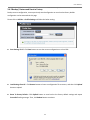
TEW‐455APBO High Power Wireless Outdoor PoE Access Point 3.4.5 Backup / Restore and Reset to Factory Backup current configuration, restore previously saved configuration or reset back to factory default configuration can be executed via this page. Please click on Utilities ‐> Profile Setting and follow the below setting.
Save Settings To PC : Click Save button to save the current configuration to a local disk.
Load Settings from PC : Click Browse button to locate a configuration file to restore, and then click Upload button to upload.
Reset To Factory Default : Click Default button to reset back to the factory default settings and expect Successful loading message. Then, click Reboot button to activate. 45 User Manual
TEW‐455APBO High Power Wireless Outdoor PoE Access Point 3.4.6 Firmware Upgrade Firmware is the main software image that system needs to respond to requests and to manage real time operations. Firmware upgrades are sometimes required to include new features or bugs fix. It takes around 8 minutes to upgrade due to complexity of firmware. To upgrade system firmware, click Browse button to locate the new firmware, and then click Upgrade button to upgrade. 1.
2.
3.
To prevent data loss during firmware upgrade, please back up current settings before proceeding. Do not interrupt during firmware upgrade including power on/off as this may damage system. Never perform firmware upgrade over wireless connection or via remote access connection.
46 User Manual
TEW‐455APBO High Power Wireless Outdoor PoE Access Point 3.4.7 Network Utility The administrator can diagnose network connectivity via the PING utility. Please click on Utilities ‐> Network Utility and follow the below setting.
Ping : This utility will help ping other devices on the network to verify connectivity. Ping utility, using ICMP packets, detects connectivity and latency between two network nodes. As result of that, packet loss and latency time are available in the Result field while running the PING test. Î
Destination IP/Domain : Enter desired domain name, i.e. www.google.com, or IP address of the destination, and click ping button to proceed. The ping result will be shown in the Result field. Î
Count : By default, it’s 5 and the range is from 1 to 50. It indicates number of connectivity test. 47 User Manual
TEW‐455APBO High Power Wireless Outdoor PoE Access Point 3.4.8 Reboot This function allows user to restart system with existing or most current settings when changes are made. Click Reboot button to proceed and take around three minutes to complete. A reminder will be available for remaining time to complete. If power cycle is necessary, please wait till completion of the reboot process. The System Overview page appears upon the completion of reboot. 48 User Manual
TEW‐455APBO High Power Wireless Outdoor PoE Access Point 3.5 System Status This section breaks down into subsections of System Overview, Associated Clients Status, WDS Link Status, Extra Information and Event Log. 3.5.1 System Overview Display detailed information of System, Network, LAN and Wireless in the System Overview page.
System : Display information of the system.
Î
System Name : The name of the system. Î
Operating Mode : The mode currently in service. Î
Location : Deployed geographical location. Î
Description : A description of the system. Î
Firmware Version : The current installed firmware version. Î
Firmware Date : The build time of installed firmware. Î
Device Time : The current time of the system. Î
System Up Time : The time period that system has been in service since last reboot. Network Information : Display information of the Network. 49 User Manual
TEW‐455APBO High Power Wireless Outdoor PoE Access Point
Î
Mode : Supports Static or Dynamic modes on the LAN interface. Î
IP Address : The management IP of system. By default, it’s 192.168.10.100. Î
IP Netmask : The network mask. By default, it’s 255.255.255.0. Î
IP Gateway : The gateway IP address and by default, it’s 192.168.10.1. Î
Primary DNS : The primary DNS server in service. Î
Secondary DNS : The secondary DNS server in service. LAN Information : Display total received and transmitted statistics on the LAN interface. Î
MAC Address : The MAC address of the LAN port. Î
Receive bytes : The total received packets in bytes on the LAN port. Î
Receive packets : The total received packets of the LAN port. Î
Transmit bytes : The total transmitted packets in bytes of the LAN port. Î
Transmit packets : The total transmitted packets of the LAN port. Wireless Information : Display total received and transmitted statistics on available Virtual AP. Î
MAC Address : The MAC address of the Wireless port. Different MAC address on each Virtual AP Î
Receive bytes :The total received packets in bytes on the Wireless port. Î
Receive packets : The total received packets on the Wireless port. Î
Transmit bytes : The total transmitted packets in bytes on the Wireless port. Î
Transmit packets : The total transmitted packets on the Wireless port. 50 User Manual
TEW‐455APBO High Power Wireless Outdoor PoE Access Point 3.5.2 Associated Clients Status It displays ESSID, on/off Status, Security Type, total number of wireless clients associated with all Virtual AP.
VAP Information : Highlights key VAP information. Î
VAP : Available VAP from VAP0 to VAP7. Î
ESSID : Display name of ESSID for each VAP. Î
Status : On/Off Î
Security Type : Display chosen security type; WEP, WPA/WPA2‐PSK, WPA/WPA2‐Enterprise. Î
Clients : Display total number of wireless connections for each VAP.
VAP Clients : Display all associated clients on each Virtual AP. Î
MAC : MAC address of associated clients. Î
RSSI : RSSI of from associated clients.. Î
Last Tx Time : Last inactive time period in seconds for a wireless connection. Î
Disconnect : Click “Delete” button to manually disconnect a wireless client in a Virtual AP. 51 User Manual
TEW‐455APBO High Power Wireless Outdoor PoE Access Point 3.5.3 WDS Link Status On/Off Status, peers MAC Address, Received Signal Strength Indicator(RSSI) and Last TX Time for each WDS are available.
WDS : Maximum supported WDS links.
Status : On/Off.
MAC address : Display MAC address of WDS peer.
RSSI : Indicate the RSSI of WDS links.
Last TX time : Last inactive time period in seconds on WDS links. For WDS with “0” RSSI, please check the devices’ WDS settings including the MAC address, wireless channel, security settings, and the TX power. If the RSSI value is much lower than expected, please try adjusting the Slot Time, ACK/CTS Timeout and/or RTS Threshold in the wireless “Advanced Setup” 52 User Manual
TEW‐455APBO High Power Wireless Outdoor PoE Access Point 3.5.4 Extra Information Users could pull out information such as Route table, ARP table, MAC table, Bridge table or STP available in the drop‐down list from system. The “Refresh” button is used to retrieve latest table information.
Route table information : Select “Route table information” on the drop‐down list to display route table. TEW‐455APBO could be used as a L2 or L3 device. It doesn’t support dynamic routing protocols such as RIP or OSPF. Static routes to specific hosts, networks or default gateway are set up automatically according to the IP configuration of system's interfaces. When used as a L2 device, it could switch packets and, as L3 device, it’s capable of being a gateway to route packets inward and outward.
ARP table Information : Select “ARP Table Information” on the drop‐down list to display ARP table. ARP associates each IP address to a unique hardware address (MAC) of a device. It is important to have a unique IP address as final destination to switch packets to.
Bridge table information : Select “Bridge Table information” on the drop‐down list to display bridge table. Bridge table will show Bridge ID and STP's Status on the each Ethernet bridge and its attached interfaces, the Bridge Port should be attached to some interfaces (e.g. eth0, ath0~ath7 and ath0.wds0~ath0.wds7). 53 User Manual
TEW‐455APBO High Power Wireless Outdoor PoE Access Point
Bridge MAC information : Select “Bridge MACs Information” on the drop‐down list to display MAC table. This table displays local MAC addresses associated with wired or wireless interfaces, but also remember non‐local MAC addresses learned from wired or wireless interfaces.
Ageing timers will be reset when existing MAC addresses in table are learned again or added when new MAC
addresses are seen from wired or wireless interfaces as well. When time runs out for a particular entry, it will be
pruned from the table. In that situation, switching packet to that particular MAC address will be dropped.
Bridge STP Information : Select “Bridge STP Information” on the drop-down list to display a list of bridge STP
information.
54 User Manual
TEW‐455APBO High Power Wireless Outdoor PoE Access Point 3.5.5 Event Log The Event log displays system events when system is up and running. Also, it becomes very useful as a troubleshooting tool when issues are experienced in system.
Time: The date and time when the event occurred.
Facility: It helps users to identify source of events such “System” or “User”
Severity: Severity level that a specific event is associated such as “info”, “error”, “warning”, etc.
Message: Description of the event. Click Refresh button to renew the log, or click Clear button to clear all the record. 55 User Manual
TEW‐455APBO High Power Wireless Outdoor PoE Access Point Chapter 4. WDS Mode Configuration Please refer to illustrations of the section 1.3 for possible applications in the WDS mode. This section provides detailed explanation for users to configure in the WDS mode with help of illustrations. In the WDS mode, functions listed in the table below are also available from the Web‐based GUI interface. Option Functions System Wireless Administrator Status Operating Mode General Settings Management System Overview LAN Advanced Settings Profiles Settings WDS Status Time Server WDS Setup Firmware Upgrade Extra Info SNMP Network Utility Event Log UPnP Reboot
Table 4‐1: WDS Mode Functions 4.1 External Network Connection 4.1.1 Network Requirement You could expand your Ethernet network via WDS link. In this mode, the TEW‐455APBO connects directly to a wired LAN, and wirelessly bridges to a remote access point via a WDS link as shown in Figure 4‐1. In the mode, it can’t associate with any wireless clients. Figure 4‐1 Point to Point Configuration 56 User Manual
TEW‐455APBO High Power Wireless Outdoor PoE Access Point 4.1.2 WDS Setup The administrator could create WDS Links to expand wireless network. When WDS is enabled, access point functions as a wireless bridge and is able to communicate with other access points via WDS links. A WDS link is bidirectional and both side must support WDS. Access points know each other by MAC Address. In other words, each access point needs to include MAC address of its peer. Ensure all access points are configured with the same channel and own same security type settings. Figure 4‐2 shows Point to Multiple Points with different VLAN settings Figure 4‐2 Point to Multiple Points with different VLAN Tag Please click on Wireless ‐> WDS Setup and follow the below setting. 57 User Manual
TEW‐455APBO High Power Wireless Outdoor PoE Access Point Note that VLAN ID in the WDS MAC List setting will only be tagged to egress packets on the wired Ethernet port. Ensure to match VLAN ID used on the network of the peer. WDS link won’t carry tags at all.
WDS MAC List Î
Enable : Click Enable to create WDS link. Î
WDS Peer's MAC Address : Enter the MAC address of WDS peer. Î
VLAN ID : By default, it’s disabled with no VLAN ID. When desired, this system supports tagged VLAN from 0 to 4094. Î
Description : Description of WDS link. The WDS link needs to be set at same Channel and Security Type. For WMM and Security settings, please refer to section 3.3. For other system management, please refer to section 3.4. Click Save button to save your changes. Click Reboot button to activate your changes 58 User Manual
TEW‐455APBO High Power Wireless Outdoor PoE Access Point 4.2 System Status This section breaks down into subsections of System Overview, WDS Link Status, Extra Information and Event Log. 4.2.1 System Overview Detailed information on System, Network, LAN Information and Wireless Information can be reviewed via this page.
System : Display the information of the system. Î
System Name : The name of the system. Î
Operating Mode : The mode currently in service. Î
Location : The reminding note on the geographical location of the system. Î
Description : The reminding note of the system. Î
Firmware Version : The current firmware version installed. Î
Firmware Date : The build time of the firmware installed. Î
Device Time : The current time of the system. Î
System Up Time : The time period that system has been in service since last reboot. Network Information : Display the information of the Network. 59 User Manual
TEW‐455APBO High Power Wireless Outdoor PoE Access Point Î
Mode : Supports Static or Dynamic modes on the LAN interface. Î
IP Address : The management IP of system. By default, it’s 192.168.10.100. Î
IP Netmask : The network mask. By default, it’s 255.255.255.0. Î
IP Gateway : The gateway IP address and by default, it’s 192.168.10.1. Î
Primary DNS : The primary DNS server in service. Î
Secondary DNS : The secondary DNS server in service.
LAN Information : Display total received and transmitted statistics on the LAN interface. Î
MAC Address : The MAC address of the LAN port. Î
Receive bytes : The total received packets in bytes on the LAN port. Î
Receive packets : The total received packets of the LAN port. Î
Transmit bytes : The total transmitted packets in bytes of the LAN port. Î
Transmit packets : The total transmitted packets of the LAN port. 60 User Manual
TEW‐455APBO High Power Wireless Outdoor PoE Access Point 4.2.2 WDS Link Status The administrator can obtain detailed Information such as MAC Address, Signal Strength of all WDS link via this page.
WDS : Maximum supported WDS links.
Status : On/Off.
MAC address : Display MAC address of WDS peer.
RSSI : Indicate the RSSI of WDS links.
Last TX time : Last inactive time period in seconds on WDS links. If display “0” RSSI, you need to check WDS configuration. Things to verify are MAC Address, Channel and Security type. Also, adjust antenna angle and Tx Power. If display unexpected RSSI, In a long distance application, you might need to adjust Slot time, ACK/CTS timeout, and/or RTS threshold. 61 User Manual
TEW‐455APBO High Power Wireless Outdoor PoE Access Point Chapter 5. CPE Mode Configuration When CPE mode is chosen, the system can be configured as a Customer Premises Equipment (CPE). This section provides detailed explanation for users to configure in the CPE mode with help of illustrations. In the CPE mode, functions listed in the table below are also available from the Web‐based GUI interface. OPTION Functions System Wireless Advance Utilities Status Operating Mode General Setup DMZ Management System Overview WAN Wireless Profile IP Filter Setup Profiles Settings DHCP Clients LAN Site Survey MAC Filter Setup Firmware Upgrade Extra Info DDNS Setup Virtual Server Network Utility Event Log Time Server Reboot SNMP UPNP Table 5‐1: CPE Mode Functions 5.1 External Network Connection 5.1.1 Network Requirement It can be used as an Outdoor Customer Premises Equipment (CPE) to receive wireless signal over last mile application, helping WISPs deliver wireless broadband Internet service to residents and business customers. In the CPE mode, TEW‐455APBO is a gateway enabled with NAT and DHCP Server functions. The wired clients connected to TEW‐455APBO are in different subnet from those connected to Main Base Station, and, in CPE mode, it does not accept wireless association from wireless clients. Figure 5‐1 CPE mode configuration 62 User Manual
TEW‐455APBO High Power Wireless Outdoor PoE Access Point 5.1.2 Configure WAN Setup There are three connection types for the WAN port : Static IP, Dynamic IP and PPPoE, Please click on System ‐> WAN and follow the below setting. In CPE mode, the WAN Port is the Wireless interface.
Mode : By default, it’s “Dynamic IP”. Check “Static IP”, “Dynamic IP” or “PPPoE” to set up system WAN IP. Î
Dynamic IP : Please consult with WISP for correct wireless settings to associate with WISP AP before a dynamic IP, along with related IP settings including DNS can be available from DHCP server. If IP Address is not assigned, please double check with your wireless settings and ensure successful association. Also, you may go to “WAN Information” in the Overview page to click Release button to release IP address and click Renew button to renew IP address again. 63 User Manual
TEW‐455APBO High Power Wireless Outdoor PoE Access Point 9
Î
Hostname : The Hostname of the WAN port Static IP : Users can manually setup the WAN IP address with a static IP provided by WISP. 9
IP Address : The IP address of the WAN port. By default, the IP address is 192.168.1.254 9
IP Netmask : The Subnet mask of the WAN port. By default, the Netmask is 255.255.255.0 9
IP Gateway : The default gateway of the WAN port. By default, the Gateway is 192.168.1.1 Î
PPPoE : To create wireless PPPoE WAN connection to a PPPoE server in network. Î
User Name : Enter User Name for PPPoE connection Î
Password : Enter Password for PPPoE connection Î
Reconnect Mode : 9
Always on – A connection to Internet is always maintained. 9
On Demand – A connection to Internet is made as needed. When the “Reconnect Mode” is set to “On Demand”, if the “System Time” NTP Client is enabled, the device’s Reconnect Mode would become “Always On” 9
Manual – Click the “Connect” button on “WAN Information” in the Overview page to connect to the Internet. Î
Idle Time : Time to last before disconnecting PPPoE session when it is idle. Enter preferred Idle Time in minutes. Î
MTU : By default, it’s 1492 bytes. MTU stands for Maximum Transmission Unit. Consult with WISP for a correct MTU setting. 64 User Manual
TEW‐455APBO High Power Wireless Outdoor PoE Access Point
DNS : Check “No Default DNS Server” or “Specify DNS Server IP” radial button as desired to set up system DNS. Î
Primary : The IP address of the primary DNS server. Î
Secondary : The IP address of the secondary DNS server.
MAC Clone : The MAC address is a 12‐digit HEX code uniquely assigned to hardware as identification. Some ISPs require you to register a MAC address in order to access to Internet. If you have resisted the computer’s network adapter MAC address with the ISP, please select “Clone MAC Address”. Î
Keep Default MAC Address : Keep the default MAC address of WAN port on the system. Î
Clone MAC Address : If you want to clone the MAC address of the PC, then click the Clone MAC Address button. The system will automatically detect your PC's MAC address.
The Clone MAC Address field will display MAC address of the PC connected to system. Click “Save” button can make clone MAC effective. Î
Manual MAC Address : Enter the MAC address registered with your ISP. Bandwidth : Administrator can control download and upload bandwidth. Default is Disable Î
Upload : The range is from 256 to 8192 in Kbits Î
Download : The range is from 256 to 8192 in Kbits Click Save button to save your changes. Click Reboot button to activate your changes 65 User Manual
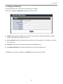
TEW‐455APBO High Power Wireless Outdoor PoE Access Point 5.1.3 Configure DDNS Setup Dynamic DNS allows you to map domain name to dynamic IP address. Please click on System ‐> DDNS Setup and follow the below setting.
Enable: Default setting is “Disable”. Select “Enable” for the device to automatically update its WAN IP address associated with the DDNS host name.
Service Provider: Select the preferred Service Provider from the drop‐down list. The options are dyndns, dhs, ods and tzo
Hostname: Host Name that is registered with the selected DDNS service
User Name & Password: User Name and Password are used to login DDNS service. Click Save button to save your changes. Click Reboot button to activate your changes. 66 User Manual
TEW‐455APBO High Power Wireless Outdoor PoE Access Point 5.1.4 Site Survey Use this tool to scan and locate WISP Access Points and select one to associate with. Please click on Wireless ‐> Site Survey. Below depicts an example for site survey.
ESSID : Available Extend Service Set ID of surrounding Access Points.
MAC Address : MAC addresses of surrounding Access Points.
Channel : Channel numbers used by all found Access Points.
Signal Level : Received signal strength of all found Access Points.
Security Type : Security type by all found Access Points.
Setup : Click “Select” to configure settings and associate with chosen AP. While clicking “Select” button in the Site Survey Table, the “ESSID” and “Security Type” will apply in the Wireless General Setup. However, more settings are needed including Security Key. For WMM and Security settings, please refer to section 3.3. For other system management, please refer to section 3.4. 67 User Manual
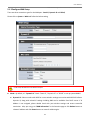
TEW‐455APBO High Power Wireless Outdoor PoE Access Point 5.2 Access Control List 5.2.1 IP Filter Setup Allows to create deny or allow rules to filter ingress or egress packets from specific source and/or to destination IP address on wired (LAN) or Wireless (WAN) ports. Filter rules could be used to filter unicast or multicast packets on different protocols as shown in the IP Filter Setup. Important to note that IP filter rules has precedence over Virtual server rules. Please click on Advance ‐> IP Filter Setup and follow the below setting.
Source Address/Mask : Enter desired source IP address and netmask; i.e. 192.168.2.10/32.
Source Port : Enter a port or a range of ports as start:end; i.e. port 20:80
Destination Address/Mask : Enter desired destination IP address and netmask; i.e. 192.168.1.10/32
Destination Port : Enter a port or a range of ports as start:end; i.e. port 20:80
In/Out : Applies to Ingress or egress packets
Protocol : Supports TCP, UDP or ICMP.
Listen : Click Yes radial button to match TCP packets only with the SYN flag. 68 User Manual
TEW‐455APBO High Power Wireless Outdoor PoE Access Point
Active : Deny to drop and Pass to allow per filter rules
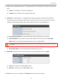
Interface : The interface that a filter rule applies All packets are allowed by default. Deny rules could be added to the filter list to filter out unwanted packets and leave remaining allowed. Click “Save” button to add IP filter rule. Total of 20 rules maximum allowed in the IP Filter List. All rules can be edited or removed from the List. Click Reboot button to activate your changes. When you create rules in the IP Filter List, the prior rules maintain higher priority. To allow limited access from a subnet to a destination network manager needs to create allow rules first and followed by deny rules. So, if you just want one IP address to access the system via telnet from your subnet, not others, the Example 1 demonstrates it, not rules in the Example 2. ¾
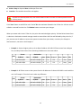
Example 1 : Create a higher priority rule to allow IP address 192.168.2.2 Telnet access from LAN port first, and deny Telnet access from remaining IP addresses in the same subnet. Rule Source Destination
Port In/Out Protocol Listen Action Side
IP/Mask Port IP/Mask
1 192.168.2.2/32 192.168.2.254/32 22 In TCP n Pass LAN 2 192.168.2.0/24 192.168.2.254/32 22 In TCP n Deny LAN ¾
Example 2 : All Telnet access to the system from the IP addresses of subnet 192.168.2.x works with the rule 1 of Example 2. The rule 2 won’t make any difference. Rule Source Destination
In/Out
Protocol
Listen Action
Side
Port
IP/Mask Port IP/Mask
1 192.168.2.0/24 192.168.2.254/32
22
In
TCP
n Deny
LAN
2 192.168.2.2/32 192.168.2.254/32 22 In TCP n Pass LAN 69 User Manual
TEW‐455APBO High Power Wireless Outdoor PoE Access Point 5.2.2 MAC Filter Setup Allows to create MAC filter rules to allow or deny unicast or multicast packets from limited number of MAC addresses. Important to note that MAC filter rules have precedence over IP Filter rules. Please click on Advance ‐> MAC Filter Setup and follow the below setting.
Access Control Type: By default, it’s “Disable”. Options are Disabled, Only Deny List MAC or Only Allow List MAC. Click Save button to save your change. Two ways to set the Access Control List: Î
Only Allow List MAC. The wireless clients in the ACL List will be allowed to access to Access Point; All others will be denied. Î
Only Deny List MAC. The wireless clients in the ACL List will be denied to access to Access Point; All others will be allowed.
MAC Address : Enter MAC address (e.g. aa:bb:cc:00:00:0a) and click “Add” button, then the MAC address should display in the ACL List. There are a maximum of 20 clients allowed in this ACL List. The MAC addresses of the wireless clients can be added and removed to the list using the Add and Delete buttons. Click Reboot button to activate your changes 70 User Manual
TEW‐455APBO High Power Wireless Outdoor PoE Access Point 5.3 Resource Sharing 5.3.1 DMZ DMZ is commonly work with the NAT functionality as an alternative of Virtual Server(Port Forwarding) while wanting all ports of DMZ host visible to Internet users. Virtual Server rules have precedence over the DMZ rule. In order to use a range of ports available to access to different internal hosts Virtual Server rules are needed. Please click on Advance ‐> DMZ and follow the below setting.
DMZ : By default, it’s “Disable”. Check Enable radial button to enable DMZ.
IP Address : Enter IP address of DMZ host and only one DMZ host is supported. Click Save button to save your changes. Click Reboot button to activate your changes. 71 User Manual
TEW‐455APBO High Power Wireless Outdoor PoE Access Point 5.3.2 Virtual Server (Port Forwarding) “Virtual Server” can also referred to as “Port Forward” as well and used interchangeably. Resources in the network can be exposed to the Internet users in a controlled manner including on‐line gaming, video conferencing or others via Virtual Server setup. Don’t repeat ports’ usage to avoid confusion. Please click on Advance ‐> Virtual Server and follow the below setting.
Virtual Server : By Default, It’s “Disable”. Check Enable radial button to enable Virtual Server.
Description : Enter appropriate message for resource sharing via Virtual Server.
Private IP : Enter corresponding IP address of internal resource to share.
Protocol Type : Select appropriate sessions, TCP or UDP, from shared host via multiple private ports.
Private Port : A port or a range of ports may be specified as start:end; i.e. port 20:80
Public Port : A port or a range of ports may be specified as start:end; i.e. port 20:80 .
The Private Port and Public Port can be different. However, total number of ports need to be the same. Example : Public Port is 11 to 20 and the Private Port can be a 10 ports range.
Click “Add” button to add Virtual Server rule to List. Total of maximum 20 rules are allowed in this List. All rules can be edited or removed from the List. Click Reboot button to activate your changes. 72 User Manual
TEW‐455APBO High Power Wireless Outdoor PoE Access Point While creating multiple Virtual Server rules, the prior rules have higher priority. The Virtual server rules have precedence over the DMZ one while both rules exist. Example 1 and 2 demonstrate proper usage of DMZ and Virtual Server rules. ¾
Example 1 : All connections should be redirected to 192.168.2.12 while DMZ is enabled. Since Virtual Server rules have precedence over the DMZ rule all connections to TCP port 22 will be directed to TCP port 22 of 192.168.2.10 and remaining connections to port TCP 20~80 will be redirected to port TCP 20~80 of 192.168.2.11 DMZ Enabled : 192.168.2.12 Rule Protocol Private IP Private Port
Public Port
1 TCP 192.168.2.10 22
22
2 TCP 192.168.2.11 20:80
20:80
¾
Example 2 : All connections should be redirected to 192.168.2.12 while DMZ is enabled. Since Virtual Server rules have precedence over the DMZ rule all other connections to TCP port 20~80 will be redirected to port 20~80 of 192.168.2.11. The rule 2 won’t take effect. DMZ Enabled : 192.168.2.12 Rule Protocol Private IP Private Port Public Port 1 TCP 192.168.2.11 20:80 20:80 2 TCP 192.168.2.10 22 22 73 User Manual
TEW‐455APBO High Power Wireless Outdoor PoE Access Point 5.4 System Status This section breaks down into subsections of System Overview, DHCP Clients, Extra Information and Event Log. 5.4.1 System Overview Detailed information on System, WAN Information, LAN Information and CPE Wireless Information can be reviewed via this page.
System : Display the information of the system. Î
System Name : The name of the system. Î
Operating Mode : The mode currently in service. Î
Location : The reminding note on the geographical location of the system. Î
Description : The reminding note of the system. Î
Firmware Version : The current firmware version installed. Î
Firmware Date : The build time of the firmware installed. Î
Device Time : The current time of the system. Î
System Up Time : The time period that system has been in service since last reboot.
WAN Information : Display the information of the WAN interface. The WAN port specified Dynamic IP, the Release and Renew button will be show‐up, click Release button to release IP address of WAN port, Renew button to renew IP address through DHCP server. The WAN port specified PPPoE, and the Connect and DisConnect button will be show up. Click “Connect” button to assigned IP address from PPPoE server, “DisConnect” button to release IP address of WAN port. 74 User Manual
TEW‐455APBO High Power Wireless Outdoor PoE Access Point Î
Mode : Supports Static, Dynamic, and PPPoE modes. Î
Reconnect Mode : The current reconnect mode of the PPPoE. Î
MAC Address : The MAC address of the WAN port. Î
IP Address : The IP address of the WAN port. Î
IP Netmask : The IP netmask of the WAN port. Î
IP Gateway : The gateway IP address of the WAN port. Î
Primary DNS : The primary DNS server in service. Î
Secondary DNS : The secondary DNS server in service. Î
Receive bytes : The total received packets in bytes on the WAN port. Î
Receive packets : The total received packets of the WAN port. Î
Transmit bytes : The total transmitted packets in bytes of the WAN port. Î
Transmit packets : The total transmitted packets of the WAN port. 75 User Manual
TEW‐455APBO High Power Wireless Outdoor PoE Access Point
CPE Wireless Information : Display the information of the Wireless interface. Î
ESSID : Display Extended Service Set ID of the wireless currently. Î
Security : Display security type of the wireless currently. Î
Status : Display connection status of the wireless currently. If the system associate with AP, the BSSID, RSSI and Last Tx Time will be show up. Below depicts the examples for associated AP of Wireless Information. Î
BSSID : Indicate the Basic Service Set ID of the associated AP Î
RSSI : Indicate the RSSI of the associated AP. Î
Last Tx Time : Indicate the last receive packet of the associated AP
LAN Information : Display total received and transmitted statistics on the LAN interface. 76 User Manual
TEW‐455APBO High Power Wireless Outdoor PoE Access Point Î
MAC Address : The MAC address of the LAN port. Î
IP Address : The IP address of the LAN port. Î
IP Netmask : The IP netmask of the LAN port. Î
Receive bytes : The total received packets in bytes on the LAN port. Î
Receive packets : The total received packets of the LAN port. Î
Transmit bytes : The total transmitted packets in bytes of the LAN port. Î
Transmit packets : The total transmitted packets of the LAN port. 77 User Manual
TEW‐455APBO High Power Wireless Outdoor PoE Access Point 5.4.2 DHCP Clients Users could retrieve DHCP server and DHCP clients’ IP/MAC address via this page.
IP address : IP addresses to LAN devices by DHCP server.
MAC address : MAC addresses of LAN devices.
Expired In : Shows how long the leased IP address will expire. 78 User Manual
TEW‐455APBO High Power Wireless Outdoor PoE Access Point 6. Command Line Interface(CLI) Help, showinfo, pwinfo, set, reboot, default and password functions are available via Telnet session. 6.1 Accessing the CLI with Telnet Follow these steps to access CLI via Telnet in the Windows XP:
Click Start ‐> Run, and type “cmd” in the “Run” field. The DOS command window appears.
Enter “telnet 192.168.10.100” to connect with system.
Enter username and password, which are root and root by default, in the Telnet session, 79 User Manual
TEW‐455APBO High Power Wireless Outdoor PoE Access Point 6.2 Accessing the CLI with SSH Utility Follow these steps to access CLI with SSH Utility (Putty) in Windows XP:
You could access CLI with SSH Utility. Below is an example using “PuTTY” utility, which is a freeware. Please see license agreement at this link http://www.chiark.greenend.org.uk/~sgtatham/putty/licence.html . TRENDnet does not provide support and warranty for using this software.
Execute Putty.exe to prompt the “PuTTY Configuration“ window. Enter IP address 192.168.10.100 on the “Host Name (or IP address)” field and select “SSH” on the “Connection type” field. Click “Open” button to open SSH session
Enter username and password, which are root and root by default, in the SSH session. 80 User Manual
TEW‐455APBO High Power Wireless Outdoor PoE Access Point 6.3 Using the CLI After accessing the CLI, the administrator can use command on the system. Using help command : Display all commands and descriptions Using showinfo command : Display System and LAN informations Using pwinfo command : Type pwinfo command, the Wireless Information Display Utility appears. Î
Choose Device : Select the desired wireless interface, ath0‐ath7 or wds0‐ wds7 9
AP Mode : Display desired AP or WDS device(interface) from ath0 to ath7 or wds0 to wds7. 9
WDS Mode : Display desired WDS device(interface) from wds0 to wds7. 81 User Manual
TEW‐455APBO High Power Wireless Outdoor PoE Access Point 9
CPE Mode : Display CPE device(Interface) ath0. Î
'Q'uit : Type Q to close this utility. Î
'W'ireless : Type W to open Choose Device window. Î
'S'ignal : Type S to open Peer MAC Address window. Type the desired MAC address of associated peer to display. Click Enter to show signal strength of associated peer. The unit is RSSI. 82 User Manual
TEW‐455APBO High Power Wireless Outdoor PoE Access Point 9
Using : The used device of system currently. 9
Watching : The MAC address of specified peer currently. 9
Signal : Indicate signal strength of specified peer currently. Î
S'T'op‐Signal : Type T to stop display signal strength. Î
'P'ing : Type P to open “Ping” window. 9
Destination : Enter IP address of destination. 9
Specify Packet Size : Enter packet size. 9
Flood Ping : Enter “‐f” to flood and Space to not flood. Click Enter to start PINGing. Click” I” to stop, and display PING statistics. Using set command : Type set command to change IP address, netmask , gateway and operating mode. 83 User Manual
TEW‐455APBO High Power Wireless Outdoor PoE Access Point Using reboot command : Restart the system Using default command : Restore system default settings
Using password command : Change root password
84 User Manual
TEW‐455APBO High Power Wireless Outdoor PoE Access Point Appendix A. WEB GUI Valid Characters Table A WEB GUI Valid Characters Block Field Valid Characters
LAN IP Address IP Format; 1‐254
IP Netmask 128.0.0.0 ~ 255.255.255.252
IP Gateway IP Format; 1‐254
Primary IP Format; 1‐254
Secondary IP Format; 1‐254
Hostname Length : 32
0‐9, A‐Z, a‐z @ ‐ _ . Manual MAC Address 12 HEX chars
IP Address IP Format; 1‐254
IP Netmask 128.0.0.0 ~ 255.255.255.255
IP Gateway IP Format; 1‐254
Hostname Length : 32
0‐9, A‐Z, a‐z @ ‐ _ . User name Password Length : 32
0‐9, A‐Z, a‐z ~ ! @ # $ % ^ * ( ) _ + ‐ { } | : < > ? [ ] / ; ` , . = MTU 576 ~ 1492
Idle Time 0 ~ 60 minutes
Primary IP Format; 1‐254
Secondary IP Format; 1‐254
Hostname Length : 32
0‐9, A‐Z, a‐z @ ‐ _ . User Name Password Length : 32
0‐9, A‐Z, a‐z ~ ! @ # $ % ^ * ( ) _ + ‐ { } | : < > ? [ ] / ; ` , . = Start IP IP Format; 1‐254
End IP IP Format; 1‐254
DNS1 IP / DNS2 IP IP Format; 1‐254
WINS IP IP Format; 1‐254
Domain Length : 32
0‐9, A‐Z, a‐z ~ ! @ # $ % ^ * ( ) _ + ‐ { } | : < > ? [ ] / ; ` , . = Lease Time 600 ~ 99999999 Seconds
WAN DDNS DHCP Server 85 User Manual
TEW‐455APBO High Power Wireless Outdoor PoE Access Point Block Field Valid Characters
Management System Name Length : 32
0‐9, A‐Z, a‐z Space ~ ! @ # $ % ^ * ( ) _ + ‐ { } | : < > ? [ ] / ; ` , . = Description Length : 40
0‐9, A‐Z, a‐z Space ~ ! @ # $ % ^ * ( ) _ + ‐ { } | : < > ? [ ] / ; ` , . = Location Length : 32
0‐9, A‐Z, a‐z Space ~ ! @ # $ % ^ * ( ) _ + ‐ { } | : < > ? [ ] / ; ` , . = New Password Length : 4 ~ 30
0‐9, A‐Z, a‐z ~ ! @ # $ % ^ * ( ) _ + ‐ { } | : < > ? [ ] / ; ` , . = Check New Password Length : 4 ~ 30
0‐9, A‐Z, a‐z ~ ! @ # $ % ^ * ( ) _ + ‐ { } | : < > ? [ ] / ; ` , . = HTTP Port 1 ~ 65535
HTTPS Port 1 ~ 65535
Telnet Port 1 ~ 65535
SSH Port 1 ~ 65535
RO community Length : 32
0‐9, A‐Z, a‐z ~ ! @ # $ % ^ * ( ) _ + ‐ { } | : < > ? [ ] ; ` , . = RW community Length : 32
0‐9, A‐Z, a‐z ~ ! @ # $ % ^ * ( ) _ + ‐ { } | : < > ? [ ] ; ` , . = RO user Length : 31
0‐9, A‐Z, a‐z ~ ! @ # $ % ^ * ( ) _ + ‐ { } | : < > ? [ ] ; ` , . = RO password Length : 8 ~ 32
0‐9, A‐Z, a‐z ~ ! @ # $ % ^ * ( ) _ + ‐ { } | : < > ? [ ] ; ` , . = RW user Length : 31
0‐9, A‐Z, a‐z ~ ! @ # $ % ^ * ( ) _ + ‐ { } | : < > ? [ ] ; ` , . = RW password Length : 8 ~ 32
0‐9, A‐Z, a‐z ~ ! @ # $ % ^ * ( ) _ + ‐ { } | : < > ? [ ] ; ` , . = Community Length : 32
0‐9, A‐Z, a‐z ~ ! @ # $ % ^ * ( ) _ + ‐ { } | : < > ? [ ] ; ` , . = IP IP Format; 1‐254
SNMP 86 User Manual
TEW‐455APBO High Power Wireless Outdoor PoE Access Point Block Field Valid Characters
General Setup (CPE Mode) ESSID Length : 31
0‐9, A‐Z, a‐z ~ ! @ # $ % ^ * ( ) _ + ‐ { } | : < > ? [ ] / ; ` , . = WEP Key 10, 26, 32 HEX chars
Pre‐shared Key 8 ~ 63 ASCII chars; 64 HEX chars
Slot Time 1 ~ 1489
ACK Time 1 ~ 372
CTS Time
1 ~ 744
RSSI Threshold ‐128 ~ 127
Beacon Interval 1 ~ 5000
DTIM Interval 1 ~ 15
Fragment Threshold 256 ~ 2346
RTS Threshold 1 ~ 2346
Slot Time 1 ~ 1489
ACK Time 1 ~ 372
CTS Time
1 ~ 744
Fragment Threshold 256 ~ 2346
RTS Threshold 1 ~ 2346
ESSID Length : 31
0‐9, A‐Z, a‐z ~ ! @ # $ % ^ * ( ) _ + ‐ { } | : < > ? [ ] / ; ` , . = Maximum Clients 1 ~ 32
VLAN ID 0 ~ 4094
WEP Key 10, 26, 32 HEX chars; 5, 13, 16 ASCII chars Group Key Update 10 ~ 99999999 seconds; default is 600
Master Key Update 10 ~ 99999999 seconds; default is 83400 Pre‐Shared Key 8 ~ 63 ASCII chars; 64 HEX chars
Authentication Server IP Format; 1‐254
Authentication Port 1 ~ 65535
Shared Secret 1 ~ 64 characters
EAP Reauth Period 300 ~ 99999999; default is 3600, 0 is disable Accounting Server IP Format; 1‐254
Accounting Port 1 ~ 65535
WEP Key Update 0 ~ 99999999 ; default is 300, 0 is disable Block Field Valid Characters
WDS Setup Peer's MAC Address 12 HEX chars
VLAN ID 0 ~ 4094 ; Space is disable
Advanced Setup Advanced Setup (CPE Mode) Virtual AP Setup 87 User Manual
TEW‐455APBO High Power Wireless Outdoor PoE Access Point Block Field Valid Characters
Description Length : 32
0‐9, A‐Z, a‐z Space ~ ! @ # $ % ^ * ( ) _ + ‐ { } | : < > ? [ ] / ; ` , . = WEP Key 10, 26, 32 HEX chars
AES Key 32 HEX chars
Source Address IP Format; 1‐254
Source Mask 0 ~ 32
Source Port 1 ~ 65535
Destination Address IP Format; 1‐254
Destination Mask 0 ~ 32
Destination Port 1 ~ 65535
MAC Filter MAC address MAC Format; 12 HEX chars
Virtual Server Description Length : 32
0‐9, A‐Z, a‐z space ~ ! @ # $ % ^ * ( ) _ + ‐ { } | : < > ? [ ] / ; ` , . = Private IP IP Formate; 1‐254
Private Port 1 ~ 65535
Public Port 1 ~ 65535
IP Address IP Format; 1‐254
IP Filter DMZ 88 User Manual
TEW‐455APBO High Power Wireless Outdoor PoE Access Point Appendix B. Network manager Privileges There are two system management accounts for maintaining the system; namely, the root and admin accounts are with different levels of privileges. The root manager account is empowered with full privilege to Read & Write while the admin manager account is Read only. The following table display CPE admin account’s privileges. Main Menu Sub Menu Group Operating Mode
Read WAN Read LAN System Read & Write DDNS Setup
Read & Write
Time Read & Write SNMP Setup
Wireless Advance Read UPNP Read & Write General Read Advanced Read Site Survey Read DMZ Read IP Filter Read MAC Filter Read Virtual Server Read System Information Read Root Password Read Admin Password
Read & Write
Login Methods Read Backup Settings Read & Write Restore Settings Read Reset to Default
Read System Upgrade Read Network Utility Read & Write Reboot Read & Write Management Administrator Admin Privilege Profile Settings 89 User Manual
TEW‐455APBO High Power Wireless Outdoor PoE Access Point Appendix C. Enabling UPnP in Windows XP 1.
Open the “Add/Remove Programs” control panel, and then click on “Add/Remove Windows Components” in the sidebar. Scroll down and find “Networking Services”, highlight it, and then click Details. 2.
In the “Networking Services” window, ensure “Internet Gateway Device” and “UPnP User Interface” options are checked. If they are not, check to enable them, as shown below, and click Ok to continue. 90 User Manual
3.
TEW‐455APBO High Power Wireless Outdoor PoE Access Point Next, in the “Control panel”, open the “Administrative Tools” and then open “Services”. Scroll down until you find the “SSDP Discovery Interface”. If the Status is not Started, double‐click on SSDP Discovery Interface to open the service properties. Change the startup type to Automatic, then close the properties. Now, right‐click on SSDP Discovery Services, and choose Start from the pop‐up menu. The SSDP Discovery Service will then be running and start each time you boot. 4.
After enabling UPnP and starting the SSDP Discovery Service, it may take few minutes for the TEW‐455APBO to be discovered and appear in your “My Network Places”. 91 User Manual
TEW‐455APBO High Power Wireless Outdoor PoE Access Point Limited Warranty TRENDnet warrants its products against defects in material and workmanship, under normal use and service, for the following lengths of time from the date of purchase. TEW‐455APBO – 3 Years Warranty AC/DC Power Adapter, Cooling Fan, and Power Supply carry 1 year warranty. If a product does not operate as warranted during the applicable warranty period, TRENDnet shall reserve the right, at its expense, to repair or replace the defective product or part and deliver an equivalent product or part to the customer. The repair/replacement unit’s warranty continues from the original date of purchase. All products that are replaced become the property of TRENDnet. Replacement products may be new or reconditioned. TRENDnet does not issue refunds or credit. Please contact the point‐of‐purchase for their return policies. TRENDnet shall not be responsible for any software, firmware, information, or memory data of customer contained in, stored on, or integrated with any products returned to TRENDnet pursuant to any warranty. There are no user serviceable parts inside the product. Do not remove or attempt to service the product by any unauthorized service center. This warranty is voided if (i) the product has been modified or repaired by any unauthorized service center, (ii) the product was subject to accident, abuse, or improper use (iii) the product was subject to conditions more severe than those specified in the manual. Warranty service may be obtained by contacting TRENDnet within the applicable warranty period and providing a copy of the dated proof of the purchase. Upon proper submission of required documentation a Return Material Authorization (RMA) number will be issued. An RMA number is required in order to initiate warranty service support for all TRENDnet products. Products that are sent to TRENDnet for RMA service must have the RMA number marked on the outside of return packages and sent to TRENDnet prepaid, insured and packaged appropriately for safe shipment. Customers shipping from outside of the USA and Canada are responsible for return shipping fees. Customers shipping from outside of the USA are responsible for custom charges, including but not limited to, duty, tax, and other fees. WARRANTIES EXCLUSIVE: IF THE TRENDNET PRODUCT DOES NOT OPERATE AS WARRANTED ABOVE, THE CUSTOMER’S SOLE REMEDY SHALL BE, AT TRENDNET’S OPTION, REPAIR OR REPLACE. THE FOREGOING WARRANTIES AND REMEDIES ARE EXCLUSIVE AND ARE IN LIEU OF ALL OTHER WARRANTIES, EXPRESSED OR IMPLIED, EITHER IN FACT OR BY OPERATION OF LAW, STATUTORY OR OTHERWISE, INCLUDING WARRANTIES OF MERCHANTABILITY AND FITNESS FOR A PARTICULAR PURPOSE. TRENDNET NEITHER ASSUMES NOR AUTHORIZES ANY OTHER PERSON TO ASSUME FOR IT ANY OTHER LIABILITY IN CONNECTION WITH THE SALE, INSTALLATION MAINTENANCE OR USE OF TRENDNET’S PRODUCTS. TRENDNET SHALL NOT BE LIABLE UNDER THIS WARRANTY IF ITS TESTING AND EXAMINATION DISCLOSE THAT THE ALLEGED DEFECT IN THE PRODUCT DOES NOT EXIST OR WAS CAUSED BY CUSTOMER’S OR ANY THIRD PERSON’S MISUSE, NEGLECT, IMPROPER INSTALLATION OR TESTING, UNAUTHORIZED ATTEMPTS TO REPAIR OR MODIFY, OR ANY OTHER CAUSE BEYOND THE RANGE OF THE INTENDED USE, OR BY ACCIDENT, FIRE, LIGHTNING, OR OTHER HAZARD. LIMITATION OF LIABILITY: TO THE FULL EXTENT ALLOWED BY LAW TRENDNET ALSO EXCLUDES FOR ITSELF AND ITS SUPPLIERS ANY LIABILITY, WHETHER BASED IN CONTRACT OR TORT (INCLUDING NEGLIGENCE), FOR INCIDENTAL, CONSEQUENTIAL, INDIRECT, SPECIAL, OR PUNITIVE DAMAGES OF ANY KIND, OR FOR LOSS OF 92 User Manual
TEW‐455APBO High Power Wireless Outdoor PoE Access Point REVENUE OR PROFITS, LOSS OF BUSINESS, LOSS OF INFORMATION OR DATE, OR OTHER FINANCIAL LOSS ARISING OUT OF OR IN CONNECTION WITH THE SALE, INSTALLATION, MAINTENANCE, USE, PERFORMANCE, FAILURE, OR INTERRUPTION OF THE POSSIBILITY OF SUCH DAMAGES, AND LIMITS ITS LIABILITY TO REPAIR, REPLACEMENT, OR REFUND OF THE PURCHASE PRICE PAID, AT TRENDNET’S OPTION. THIS DISCLAIMER OF LIABILITY FOR DAMAGES WILL NOT BE AFFECTED IF ANY REMEDY PROVIDED HEREIN SHALL FAIL OF ITS ESSENTIAL PURPOSE. Governing Law: This Limited Warranty shall be governed by the laws of the state of California. Some TRENDnet products include software code written by third party developers. These codes are subject to the GNU General Public License ("GPL") or GNU Lesser General Public License ("LGPL"). Go to http://www.trendnet.com/gpl or http://www.trendnet.com Download section and look for the desired TRENDnet product to access to the GPL Code or LGPL Code. These codes are distributed WITHOUT WARRANTY and are subject to the copyrights of the developers. TRENDnet does not provide technical support for these codes. Please go to http://www.gnu.org/licenses/gpl.txt or http://www.gnu.org/licenses/lgpl.txt for specific terms of each license. PWP05202009v2 93 User Manual
TEW‐455APBO High Power Wireless Outdoor PoE Access Point 94