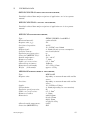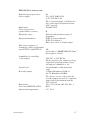
1
EXTOX-UNI i-1
INTELLIGENT STATIONARY GAS CONCENTRATION
MEASURING DEVICES
MANUAL
www.gazerzekelo.hu
MŰSZER AUTOMATIKA KFT.
Manufacturer
:
Service
H-2030 Érd, Alsó u. 10., Pf. 56. Hungary
Telephone :
+36 (23) 365-087, 365-152, 365-280,
366-748, 366-838
Telefax:
+36 (23) 365-837
E-mail :
[email protected]
H-2040 Budaörs, Baross u. 77.
:
CONTENTS
i1konyvAng.doc
1
1.
PURPOSE OF DEVICES
2.
MAIN FEATURES
3.
CONSTRUCTION
4.
DESCRIPTION OF OPERATION
4.1.
4.2.
5.
INSTALLATION AND PUTTING INTO OPERATION OF DEVICE
5.1.
5.2.
5.3.
5.4.
6.
Conditions of installations
Placement of transmitter and central unit
Cabling of transmitter and central unit
Conditions of installation, installation
HANDLING AND OPERATIONAL INSTRUCTIONS
6.1.
6.2.
6.3.
6.4.
7.
Operation of central unit
Operation of transmitters according to applied sensors
Handling units, status signals
Connection points
Operation, handling, interpretation of status signals
Cleaning
CONDITIONS OF SAFE OPERATION
7.1.
7.2.
7.3.
Operation in explosion dangerous environment
Aspects of protection against indirect contacts
Meanings of abbreviations and signals
8.
TECHNICAL DATA
9.
GUARANTEE
10.
SERVICE, MAINTENANCE
11.
APPENDIX
Manuals of transmitters E-TD-P1 and E-TD-S1, manufacturer’s statement ,
attached drawing
i1konyvAng.doc
2
1.
PURPOSE OF DEVICES
Az EXTUX-UNI i-1 is general purpose gas and solvent vapour sensing
apparatus which meets the requirements of industrial users in the first
place according to the latest directives and standards of European
Union. Its purpose is the supervision of zones and places, the
measurement of concentration of dangerous contaminating materials
which mixed into the air for some reason( i.e.risk of explosion and toxic
danger) and to avert dangers by automatic actuation control.
2.
MAIN FAITURES
→ Stationary system with transmitters
→ Measurement of concentration of explosive, toxic and other materials
by means of different type transmitters
→ Processor controlled intelligent central unit suitable for operation of
single transmitter
→ Continuous concentration and status display
→ Programmable 4 detection levels +acknowledging acoustic signal +
self error
→ Acoustic signal control adapted to any signal level
→ Distinguished control according to signal levels on the acoustic
relay output
→ Potential-free or voltage controlled acoustic relay output
→ Built-in service key switch, detection and displaying of switching to
service status
→ Recorder output
→ Indication of power supply failure in uninterrupted service
→ Event recording
i1konyvAng.doc
3
3.
CONSTRUCTION
4.
The EXTOX-UNI i-1 gas concentration measuring devices are built of
transmitters and central units . The transmitters and central units can be
connected together by transmitter cables. The transmitter includes measuring
transducer which transforms gas concentration into electric signals, while the
central units operate the transmitters and elaborate the elecric signals of them
which depend on gas concentration.
The device can operate with many types of transmitters. The types of
transmitters are determined by the concentration of chemicals the measuring
range and the danger rate existing in the area.
The internal constructions of central units are partly different because of the
different parameters of various transmitters.
DESCRIPTION OF OPERATION
4.1.
OPERATION OF CENTRAL UNITS
The task of central unit type EXTOX-UNI i-1 is to operate the connected
transmitters, processing the incoming electric signals which are coming from
transmitters dependending on gas concentration, information transfer, output
of alarm signals ,control of actuation as well as event recording.
Its performance conform to the type and technical features of transmitters
and measuring range. They have four signalling levels ,in addition self error
and acoustic signal, with relevant potential-free relay output contacts.The
signal levels, the values between the switching on and off of the signal levels,
(hysteresis) signalling for increasing or decreasing concentration, blocking of
the signals (switching off either by manual cancellation or automatically)and
the operation of relay outputs ( to close or brake in active state) are
programmable.The individual signal levels can be used for any actuation
control functions upon request, but the basic signal level settings No 1 ,2,
and 3 are of advance signal types i.e. they are resetted automatically and their
relay outputs close, if the signal is active. The 4th signal level is of alarm type
and cannot be switched off automatically, the relay output brakes in the case
of active signal. The changing of its basic setting is not recommended. For
safety reason the application of 4th signal level is recommended for emergency
stop, disconnection of the current,closing of gasmagnetic valve etc.
Switching out of the signal levels is possible by the reset button, if it has block
setting and the concentration allows it anyway.The relay output of self- error
brakes in the event of failure.This signal is not blockable one, the reset button
is ineffective on it. The acoustic signal may be assigned to any signal level,
its relay output gives out shortcircuit or mains voltage in active state,
depending on the application of jumpers inside the apparatus. The device
controls the acoustic alarm in such a way that it can be decided which signal
level is active by means of the sound as well. The acoustic alarm gives out
successive sound pulses repeated at regular intervals, the number of which
corresponds to the highest number of actice signal levels. Switching the
acoustic alarm off is possible bay means of the reset button. For acoustic
alarms, we have to use the ones with continuous and identical sound for the
above indicated operation.
i1konyvAng.doc
4
The apparatus starts operation with 1 minute delay after switching on because
of the features of the sensors. During timing the relays are not active, the
signal levels are not activated. This is self-error, while with reference to the
4th signal level it means state of danger warning. After timing period the
relays and the status indicator LED-s are adjusted to operational state,
determined by the actual concentration.
The actual concentration may be traced permanently on 3-digit 7 segment
LED display. The display shows the values according to the measurement
ranges as follows:
*
*
*
in LEL %,
in volume %
in ppm.
In case of significant excess of measuring range the device becomes
overdriven. Inscription of „OVL” will appear on the display, the signals
programmed for increasing concentrations remain switched on,
not
depending on the further changes of concentration.
In such cases the reason of overdrive should be checked and it must be
terminated. The state of overdrive is allowed to be cancelled only afterwards,
either by pushing the inner pushbutton, or the continuous pushing of reset
button for more than 15 seconds. Caution! The state of overdrive is allowed to
be cancelled after making sure evidently, that no dangerous concentration is
available.
The signal levels ,the self-error signal and the state of acoustic signals are
displayed by the LED-s located on the front panel. Red colored LED-s belong
to the singal levels and the acoustic signal, which illuminate in active state of
the signals. The color of LED-s indicating the operation/self-error, and
network/uninterrupted is green. The LED of operation/self-error illuminate
during the operation, it is switched off in case of failure.
The LED of network/uninterrupted operation illuminate permanently in
network operation, in the event of power failure it is flashing. The apparatus
recognizes the power failure on the basis of information, coming from the
UPS.
The apparatus includes recorder output as well, which makes it possible to
further analyse the gas concentration in analogue format, in range of 4-20 mA
or 0.4-2V. In case of self-error the output current decrases significantly below
4 mA, and the output voltage below 0.4 V.
The apparatus operates from supply voltage of 230V 50 Hz or from 24 V direct
voltage. Making its operation uninterrupted is proposed by means of purposemade UPS of 24 V . The apparatus also has built-in service switch, which is
capable in service status to shortcircuit the contact, belonging to the 4th
signal level.
In service position the apparatus displays alternately the inscription of
„SER” and the actual concentration ,and furthermore makes logging on time
of switching on and off of service status.
i1konyvAng.doc
5
4.2.
OPERATION OF TRANSMITTERS ACCORDING TO APPLIED SENSORS
The EXTOX-UNI i-1 gas sensitive devices are working basically on four
measurement principles. Depending on type of materials and measuring range
they are available with the following sensors:
*
*
*
*
semicoductor,
catalytic,
infrared and
electrochemical.
In the case of semiconductor based sensors the sensitive element is directly
connected to the central unit without processing electronics. The measuring
transducer makes use of the characteristics of special purpose semiconductor
i.e. the elactrically heated semiconductor layer can change its conductivity i.e.
resistance considerably.The performance of sensors is typically nonlinear as a
function of concentration.
In the case of use of catalytic sensors a platinum filament is heated by electric
current in the measuring transducer.The platinum filament is surrounded by
catalyzer material. The catalyzer is capable of oxidizing the flammale
materials even below normal combustion temperature in presence of oxygen of
air. This oxidation goes with temperature increase depending on the
concentration of inflammable material, which increases the resistance of
heated platinum filament. This can be detected as an electric signal in a bridge
circuit. In this case the sensor also coupled directly to the central unit.
In the case of application of infrared sensors the measurement of
concentration is based on the light absorption properties of the material to be
measured in infrared spectrum . The change of absorption as a function of
concentration is detected and transformed into electric signal by the sensor.
This electric signal is converted into output current of range of 4-20 mA by
the transmitter’s electronic circuits, which are interconnected to the sensor.
This output current is in direct proportion to the concentration.
In the case of application of electrochemical sensors the detecting elements
generate electric current by means of chemical reactions as a function of
measured material concentration. The signal processing electronics amplify
the output current of the sensor and convert it into the range of 4-20 mA
current consumption. The properties of electrochemical transmitter conform
to the properties of applied electrochemical sensors.
The apparatus enables the application of other transmitter types of 4-20 mA
as well.
i1konyvAng.doc
6
EXTOX-UNI E-TD-S1
It is designed for measurement of concentration of numerous inflammable
and explosive materials and operates with semiconductor transducers,
stationary, diffusion type, explosion proof transmitter.
EXTOX-UNI E-TD-P1
It is designed for measurement of concentration of several inflammable and
explosive materials and operates with catalytic measuring transducers,
stationary, diffusion type, explosion proof transmitter.
EXTOX-UNI IRTA-1 and IRTA-2
It is designed for measurement of concentration of carbon dioxide with
infrared measuring transducer, stationary, diffusion type, not explosion proof
transmittes.
MWG-100NE
It is designed for measurement of concentration of several toxic materials
and oxygen and operates with electrochemical measuring transducers,
stationary, diffusion type, not explosion proof transmitter.
i1konyvAng.doc
7
5.
INSTALLATION AND PUTTING INTO OPERATION OF DEVICE
5.1.
CONDITIONS OF INSTALLATION OF DEVICE
The EXTOX-UNI gas concentration measuring devices can be installed only in
such places, the requerements of which are satisfied by the technical
parameters of the instruments. Furthermore the installation site should be
selected in a way, that the possibility of usual maintenance works and the
proper and safe operation can be ensured.
Since the two parts of the apparatus, the central unit and the transmitter have
completely different electrical characteristics, we have to take different rules
into account.
The central units and the cable junction boxes are of non-explosion proof ones
therefore using them in explosion dangerous rooms or sectors is forbidden.
The transmitters may be installed according to the prescriptions of manuals
only.
In the event the installation is stipulated by the authorities, the installation
should be based on a project plan. The regulations of that should be complied
with and the content of project plan should not contradict the installation
rules hereby mentioned.
If no detailed project plan of installation is available or the procedure of it is
uncertain, please contact the company service or the experts of manufacturer
to clarify the questions.
5.2.
PLACEMENT OF TRANSMITTER AND CENTRAL UNIT
The placement of transmitter and central unit is determined by project plan.
In lack of it, its placement can be decided only with care. The placement of
transmitters can be determined according to the informations indicated in the
manuals.
In the case of the central units we have to choose such places outside the
sector limits but within the range of maximum possible installation distance
where the environmental circumstancies are suitable for operation and the
easy handling and rational cabling can be ensured. The central unit should
be protected against the effect of heat radiation and can be operated only in
allowed temperature range.
If cable junction box is applied to the apparatus, it should be placed close to
the central unit considering space and trace requirements of applied cables.
i1konyvAng.doc
8
The EXTOX-UNI i-1 type central unit should be mounted on even surfaced
vertical wall.
When placing the transmitters (sensors) the shape of free air-space, the
location of hazardous points, the occasional air flows and the density of
occuring gases are to be taken account.
For gases lighter than air {H2, CH4, CO, NH3} the sensors shall be placed in
the upper part of air space, for heavier gases they must be put into lower
locations. The solvent vapours are heavier than air.
5.3.
CABLING OF TRANSMITTER AND CENTRAL UNIT
The transmitter of gas concentration measuring devices type EXTOX-UNI i-1
should be connected by separate cable to the appropriate central unit of
relevant manufacturing number.
All the cables, but in particular the cables connecting the central unit and the
transmitters shall be definitely identifiable. Into the transmitters we can
couple only such cables, the diameter and core cross section of which meet
the requirements of the technical data of the transmitters .
When cabling the transmitter , to be installed into explosion dangerous zone
the prescriptions of MSZ EN 60079-14 should be taken account.
The loop resistance of transmitter cable shall not exceed the highest allowed
value. The transmitter cable should be affixed within distance of 40 cm from
the transmitter. We have to strive for minimization of the the line section
within the sector limits when designing the trace of transmitter cables without
having definite project plan. Lapping in transmitter cables should be avoided
if possible. Nevertheless if this is unavoidable, in explosion dangerous space
lapping is allowed only in certified explosion-proof connectionbox.For
cabling we can use the offered cables or technically suitable replacement
types. If there are electric circuits of different voltage levels towards the
actuating units, the wires of them shall not be placed in the same cable
bundle.
When cabling the nacessary cables ( of transmitter ,actuating, supplying
accoustic signal etc.) should be installed on the designed cable traces. When
determining the cable lengths we have to reckon with connectability
(allowances). The connecting of cables is not the job of the cable mounting
experts, but this process is part of installation.
i1konyvAng.doc
9
5.4.
CONDITIONS OF INSTALLATION, INSTALLATION
The preconditions of putting into operation are the existence of properly
installed gas sensitive apparatus alongwith cabling and power supply.
The installation of the apparatus can be performed by an authorized expert
who attended courses of operators ,technical head of repairment service of
damp-proof and explosion-proof electrical equipments and having proficiency
of proper installation of EXTOX-UNI i-1 type gas detectors.
During installation the cables of apparatus should be connected.The actuating
electrical circuits which are connected to relay contacts should be checked
according to loadability, the power supply according to its parameters and
the complete apparatus in respect of explosion-proof requirements. After
getting favourable results a computer should be connected to the device in
which a diagnostic program, suitable for the commissioning and maintenance
of EXTOX-UNI i-1, is running.
The apparatus can be energized and afterwards total operational inspection
should be performed by means of calibration material.The data of installation
are stored in the computer. On the basis of stored data, an installation
protocol is made on successful installation, duly signed by the insallation
person and the customer or his/her representative, accepting the works.
The total operation inspection includes the inspection of the apparatus only,
the check of operation of actuating circuits of relay contacts is not included.
This way for example if the actuating circuits are not built up by the time of
the installation, the gas sensitive devices can be installed anyway. It is worth
carrying out the installation in such a predetermined period so that the
complete system can be tested alongwith emergency ventilation, gas magnetic
valve, acoustic and light signals in order to avoid later possible malfunctions.
The installation can be performed upon order. The planned date and
circumstancies of installation should be checked with our service 3-4 days in
advance at the following address:
Address:
2040 Budaörs, Baross u. 77.
Telephone/fax: +36 23 416 761
If the conditions of installation are not ensured or the technical circumstancies
are not suitable in the predetermined period and promt solution is not possible
,the installation fails by mistake of customer.This fact is to be written in the
duly signed protocol as well.
In this case the failed installationt is at the cost of the customer’s.
i1konyvAng.doc
10
6.
HANDLING AND OPERATIONAL INSTRUCTIONS,
6.1.
HANDLING UNITS, STATUS SIGNALS
On central units the following handling units are available:
*
*
*
*
*
*
*
*
*
*
*
*
i1konyvAng.doc
three digit seven segment LED,
acoustic signal LED (red),
4th signal level (red),
3rd signal level (red),
2nd signal level (red),
1st signal level (red),
network / uninterrupted operation LED (green),
operation / self error LED (green),
reset (acknowledging) botton,
service switch with key,
overdrive comparator cancellation button (accessible only after
removing cover ),
computer communication connection point (accessible only after
removing cover ),
11
6.2.
CONNECTION POINTS
230V L
230V N
HANG N
HANG L
mains supply phase conductor
mains supply neutral conductor
acoustic signal relay contact, under potential it is neutral
conductor
acoustic signal relay contact, under potential it is phase
conductor
JSZ4
JSZ4
JSZ3
JSZ3
JSZ2
JSZ2
JSZ1
JSZ1
OH
OH
RK+
GND
SZM+
SZML
SZM-
4th signal level relay contact
4th signal level relay contact
3th signal level relay contact
3th signal level relay contact
2nd signal level relay contact
2nd signal level relay contact
1st signal level relay contact
1st signal level relay contact
self error relay contact
self error relay contact
recorder output positive pole
recorder output negative pole
supply of 24V positive pole (for UPS)
uninterrupted operation sensing point (for UPS)
supply of 24V negative pole (for UPS )
F+
X
Y
GND
E-TD-S1 transmitter connection point
E-TD-S1 transmitter connection point
E-TD-S1 transmitter connection point
E-TD-S1 transmitter connection point
F+
FK
GND
E-TD-P1 transmitter connection point
E-TD-P1 transmitter connection point
E-TD-P1 transmitter connection point
+
Iki
Ibe
GND
4…20mA
4…20mA
4…20mA
4…20mA
transmitter connection point
transmitter connection point
transmitter connection point
transmitter connection point
Remark : out of listed transmitter connection points, the apparatus
always contains only the relevant connection points of applied
transmitter.
To the 4-20mA transmitters belong EXTOX-UNI IRTA-1 and IRTA-2,
alongwith types of MWG-100NE as well .
i1konyvAng.doc
12
6.3.
OPERATION , HANDLING, INTERPRETATION OF STATUS
SIGNALS
The operation of EXTOX-UNI i-1 gas concentration measuring apparatus
can be traced by means of the signals of central units. The operation of
instrument is displayed by the light of the LED-s as follows: „operation/selferror, „network/uninterrupted” and the light of 3-digit indicator. If a UPS is
connected properly to the apparatus, the LED of „network/uninterrupted”
may not only illuminate continuously but it can flash as well. Even if it is
flashing, the apparatus works properly but it indicates only that according to
the UPS, no network voltage is available.
When switching on, the device starts operation after timing of 1 minute
approximately. During timing period the LED-s of signal levels and acoustic
alarm do not light. On the indicator temporarily not the real concentration
values will appear and the decimal points illuminate alternately in succession.
After timing period the measured concentration value can be read
permanently. The signals start operation according to the measured
concentration and the preprogrammed signal levels. The LED of a given
signal level will illuminate, i.e. the signal is active, if the concentration
reaches the preprogrammed value.The activation of signals will activate the
acoustic signal as well.The acoustic signals can be cancelled by the reset
puhsbutton.
The signals, which are not blockable according to the programming ,will be
reset automatically in the function of concentration. The blockable signals can
be cancelled by the reset button only, provided that the concentration allows
it.
In the event the concentration exceeded the measuring range significantly
inscription of „OVL” appears on the display. In this case the signals,
activated by increasing levels, cannot be cancelled. The reason of this state
should be checked by all means and it must be terminated. After that the reset
button should be pushed continuously for minimum 15 sec, the normal
operation will be reset only in this way.
If the „operation/self-error” LED goes out, it means the failure of the
apparatus. In case of certain errors it can be observed on the operation of the
indicator as well , e.g. non-interpretability of the signal, or on the basis of
irregular brightness distribution among the segments.In this case the
responsible person is to switch the apparatus into service status by the service
button, after realizing that there is no dangerous concentration around, in
order to ensure the safe operation of the supervised institution.In service
status the instrument shows the inscription of ”SEr”, together with a
concentration value alternately, if the type of failure allows it.The displayed
concentration figure cannot be considered as realistic. The failured apparatus
is not capable to fulfil its duty properly in service state either. The reparation
of the apparatus must be arranged.
i1konyvAng.doc
13
6.4.
CLEANING
The cleaning of devices is only needed, if dirt impedes operation.
The removal of such dirts usually requires disassembling of the apparatus,
which is the job of the service.
In other cases cleaning is allowed, but this cannot endanger the safe
operation.
Water or other chemicals are not allowed to get into the apparatus. Use of
solvents that can damage the cover, are not allowed either.
7.
CONDITIONS OF SAFE OPERATION
7.1.
OPERATION IN EXPLOSION DANGEROUS ENVIRONMENT
It is prohibited to connect the central unit of EXTOX-UNI i-1 to such
electrical appliances, that are not necessary for proper use or the electrical
parameters of which exceed the limits, indicated in the technical data of the
apparatus!
In the gas sensitive apparatus any modification is prohibited without
permition of the manufacturer.
In explosive environment only approved explosion-proof transmitters are
allowed to use.
The detailed conditions of safe application of explosion-proof transmitters
can be seen in their separate manuals.
7.2.
ASPECTS OF PROTECTION AGAINST INDIRECT CONTACT
The central units are electrical devices that are operated by supply voltage of
230 V. Opening of their enclosure under voltage by unauthorized persons is
forbidden and dangerous to life. The cabling of central unit and cable junction
box (if any) to be made in a way that the reinforced insulations are not to be
damaged among the electric circuits of different voltage levels.The connection
of devices are to be made according to the allotment of connecting points or
description of handbook of connections.
The transmitter is not to be connected to the earthing wire, but for
example the mounting onto earth-connected iron framing is allowed.
The device type EXTOX-UNI i-1 is of plastic armoured one
with reinforced insulation and belongs to protection class II. This device
shall not be connected to earth conductor wire.
i1konyvAng.doc
14
If the user supplies separate break switch protected cable for the power supply
of the gas detection devices, the break switch (or mains switch if any) should
be located close to the gas detection apparatus and it should be indicated,
which device is operated by them.
Remark : since the gas detection instruments are safety devices of continuous
operation and switching them off is possible only in justified situation, e.g.
when servicing them, it is practical, that the inscription of „Switching off
prohibited” to be indicated close to the main switch or break switch.
7.3.
MEANINGS OF ABBREVIATIONS AND SIGNALS
LEL%
Volume %
ppm
Lower Explosion Limit in percentage
Volume percentage
parts per million
(parts per million of given volume)
F3
F4
Mains fuse
Fuse for acoustic relay contact (It has role only in cases
under potential )
Device protected by double or reinforced insulation
Caution ! (Reference to the documentation !)
The apparatus meets the relevant requirements of
European Union standards
i1konyvAng.doc
15
8.
TECHNICAL DATA
EXTOX-UNI E-TD-S1 SEMICONDUCTOR TRANSMITTER;
Detailed technical data and prescriptions of application are in its separate
manual .
EXTOX-UNI E-TD-P1 CATALYTIC
TRANSMITTER;
Detailed technical data and prescriptions of application are in its separate
manual .
EXTOX-UNI INFRARED TRANSMITTER;
Type :
Measured material:
Response time, (t90):
Precision of repetition:
Supply :
Output signal :
Sensitive element :
Explosion-proof protection :
Protection {MSZ IEC 529} :
Outside temperature :
Diameter of cables:
Cable core cross section:
Allowed loop resistance:
Dimensions (with stand):
Weight
(with stand):
MWG100NE ELEKTROCHEMICAL
Type:
Response time:
Precision:
Supply:
Current drain:
Explosion- proof protection:
Cable core cross section:
Diameter of cables:
Dimensions:
Allowed outside temperature:
Protection (MSZ IEC529):
i1konyvAng.doc
EXTOX-UNI IRTA-1 and IRTA-2
carbon dioxide
22s
±0.2%
19...28V DC, max 180mA
4...20mA (linear) current consumption
two-beam infrared
no
IP 54
-20...+40 °C
7...9mm
0.5...1.5mm2
10Ω max.
135 x 126 x 95 mm
approx. 0.55 kg
TRANSMITTER;
MWG100NE
depending on measured materials and the
sensor
depending on measured materials and the
sensor
14...28V Direct Voltage
4...20mA (depending on concentration)
No
0.5...1.5mm2
9...11mm
width:102mm
height:170mm
depth: 58mm
weight: kb. 850g
0-40oC
IP32
16
EXTOX-UNI i-1 CENTRAL UNIT;
Explosion-proof protection:
Power supply:
Mains fuses:
Class of protection
against indirect contact:
Measuring range:
Operated transmitter:
No
210...242V 50Hz 14VA,
or 22...28V DC 0.3A
The occasional supply of 24V may be
only with reinforced insulation from
230V network.
125mAT 250V
II.
Identical vith measuring range of
transmitter
E-TD-S1 (semiconductor)
E-TD-P1 (catalytic)
Other ones with 4…20mA output
Max. loop resistance of
transmitter cables of transmitter
types E-TD-P1 and E-TD-S1:
3Ω
(with cable of SZRMK VMJ 4X1.5mm2
this is approx. 150m)
Loadability of controlling
relay outputs:
250V AC, or 30V DC 4A.
On the acoustic relay output in voltage
controlled version the mains voltage
will appear, loadability is 1A.
Signal levels:
Programmable within measuring
range
Recorder output:
4-20mA, Rloadmax=220Ω ,or
0.4-2V, Rloadmin=100KΩ
The electric circuit connected to the
recorder output can only be separated
with reinforced insulation from the
230V network.
Dimensions:
310 x 165 x 94 mm (Wi., Hei.,Dee.)
Protection (MSZ EN 60529):
IP65
Operational temperature:
0 oC...40oC
i1konyvAng.doc
17
BASIC CABLE JUNCTION BOX;
Power supply:
Individual power consumption:
Protection (MSZ EN 60529):
Potential-free relay contacts
and loadability:
Um
(Inner relay operationg voltage):
230V ± 10% 50Hz
20VA
(added to power consumption of central
unit)
IP54
* sound; 1 pce of closing 250V 5A 50Hz}
* prealarm; 2 pcs of closing 250V 5A
{50Hz}
* alarm; 2 pcs of droping 250V 5A
{50Hz}
24V AC
At different designs the data are subject to change!
MEASUREMENT TECHNIQUE DATA OF THE INSTRUMENTS (TRANSMITTER AND
CENTRAL UNIT TOGETHER );
Response time , (t50, t90):
Precision:
i1konyvAng.doc
Depending on applied transmitters and
measured material, see technical data of
transmitters ,in case of E-TD-S1, E-TDP1 according to MSZ EN 50054:2000 and
MSZ EN 50057:2000
Depending on applied transmitters and
measured material, see technical data of
transmitters ,in case of E-TD-S1, E-TDP1 according to prescriptions of MSZ EN
50054:2000 and MSZ EN 50057:2000
18
9.
GUARANTEE
Műszer Automatika Ltd undertake guarantee of gas concentration measuring
devices types EXTOX-UNI K1/K2 for 1 year after date of installation, if the
instruments are properly used.
The guarantee refers to failures, originated from manufacture. The conditions
of guarantee subject to full observance of prescriptions of installation,
commissioning, handling and safe operation.
10.
SERVICE, MAINTENANCE
The gas detection devices need regular servicing, so that they can operate
perfectly in long term. The maintance works cover not only the assessment of
general technical conditions but the checking of parts and their mountings
which determine the explosion-proof protection , the control of operation and
if necesarry the error correction and rectification of setting.
The prevention of occasional operational abnormalities is also possible
beside the regular maintenace .
In case of failure, for fast error-correction, the following data should be
specified:
*
*
•
•
location of system installation,
date of failure,
description of failure
circumstancies of failure occurence
Maintenance contract can be prepared with the service staff of Műszer
Automatika Ltd. after the guarantee period of 1 year. By the contract the
periodical regular maintenance of the apparatus can be ensured in advance.
i1konyvAng.doc
19