1
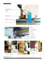
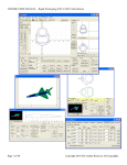
DigiFence Installation Instructions
Please note this installation kit is designed solely for installation on the Commercial Powermatic Accufence (and Commercial Jet
XACTA Fence II). Accurate Technology manufactures kits for other fences in which some or all of the components may be
different. For more information about ProKits™ please contact Accurate Technology.
Warranty
Accurate Technology, Inc., warrants DigiFence™ systems against defective parts and workmanship,
commencing from the date of original purchase. Upon notification of a defect, Accurate Technology, Inc.
shall have the option to repair or replace any defective part. Such services shall be the customer's sole and
exclusive remedy. Expenses incidental to repair, maintenance, or replacement under warranty, including
those for labor and material, shall be borne by Accurate Technology, Inc.
Except as expressly provided in this warranty, Accurate Technology, Inc., does not make any warranties with
respect to the product, either expressed or implied, including implied warranties of merchantability or fitness
for a particular purpose, except as expressly provided in this agreement.
Accurate Technology, Inc., shall not be liable for any special, incidental, or consequential damages, for loss,
damage or expense directly or indirectly arising from the customer's use of or inability to use the equipment,
either separately or in combination with other equipment.
Tools Required
Set of small clamps
Drill Motor
Center punch
9/32” drill bit (OR 5/16” drill bit)
Adjustable wrench
Phillips screw driver
Tap Handle
Allen wrench set
Some parts of this installation kit may have been pre-assembled for your convenience by Accurate
Technology.
Due to small differences in fence designs, parts and installation may differ slightly from those shown.
Installation Photos:
Digital Readout
Bracket
Tab Protector
Readhead
Scale
Display
Display Bracket
Scale
Readhead
Guide Clip
Tab Protector
5/16-18 nut
¼-20 x ½” Bolt
Accurate Technology Inc.
800-233-0580 828-654-7920 Fax 828-654-8824
Instructions # AccuFence AND Jet Retrofit Instructions. Last updated 1-12-06
2
Mounting the Scale:
1. Place the scale on the underside of the fence tube so the right end of the scale is flush with the right
end of the fence tube, and the inside edge of the scale rests against the edge of the angle iron.
2. Use a center punch to mark the hole locations on the underside of the fence.
3. Drill and tap holes into the fence tube (using the supplied drill and tap) at the marked locations. Be
sure the holes go completely through the metal. Remove any burrs.
4. Attach the scale using the supplied flathead screws. Be sure the screw heads are flush or below the
surface of the scale.
5. Slide the readhead back onto the scale (if it was removed). Be very careful to not damage the sensitive
grounding fingers inside.
Mounting the Digital Readout Bracket:
6. Remove the bolt that holds the cam lever to the fence.
7. Replace it with the supplied 5/16 x 2” bolt.
8. Slide the digital readout bracket onto this bolt (lower hole of the digital readout bracket).
9. Reinstall the 5/16-18 nut. Hold the bracket level and tighten the nut.
10. Mark the position of the digital readout bracket’s upper hole onto the fence (using a center punch).
11. Temporarily loosen the 5/16-18 nut (from step 9), and let the digital readout bracket swing clear of the
marked hole.
12. Drill the marked position with a 9/32” drill bit. Be sure to drill through both sides of the fence. Use
the photos on the previous page as a guide.
13. Slide the supplied ¼-20 x ½” bolt through the right hole (from the inside of the cam lock area), and
into the upper hole of the digital readout bracket. Install the supplied ¼-20 nut and tighten.
14. Tighten the 5/16-18 nut. (Do not over tighten this nut; it could make the fence lock hard to operate.)
Accurate Technology Inc.
800-233-0580 828-654-7920 Fax 828-654-8824
Instructions # AccuFence AND Jet Retrofit Instructions. Last updated 1-12-06
3
Guide Clip Installation and Setup:
15. Place two 8-32 x ¾” screws through the guide clip. (The slots of the guide clip should be on the same
side as the screw heads.)
16. Slide a #8 aluminum spacer over each of the screws.
17. Attach this assembly to the tab protector as shown in the photos.
18. Loosely mount the tab protector to the underside of the digital readout bracket using the supplied 8-32
x 3/4” pan head screws. Do not tighten completely at this time.
19. Slide the readhead along the scale and up to the digital readout bracket assembly.
20. Center the guide clip over the post on the readhead so that it applies light pressure. Use the supplied
washers and spacers to achieve the correct pressure (the guide clip should flex approximately
1/16”). Tighten all screws.
21. Slide the fence left and right and check for binding. Assure the readhead post remains centered in the
guide clip, with constant pressure over the full range of fence travel.
Digital Readout Installation:
22. Remove the two screws on the front of the digital readout housing and set them aside. Pull the cover
off of the base. Drill out the upper left and lower right hole locations (they are partially drilled
already). Attach the digital readout base to the digital readout bracket using the supplied flathead
screws. Replace the digital readout cover and tighten screws.
23. Connect the readhead cable to the digital readout.
24. Verify the digital readout reads larger positive numbers when moved from left to right. If it does not,
the readhead can be reversed on the scale, or the digital readout’s reading direction can be changed
(consult the included User Manual for details).
Accurate Technology Inc.
800-233-0580 828-654-7920 Fax 828-654-8824
Instructions # AccuFence AND Jet Retrofit Instructions. Last updated 1-12-06
4
Calibration:
(See User Manual for reference)
1. With the fence locked in position near the saw blade, cut a small square board.
2. Measure this board with the most precise measuring tool available and write down the measurement.
3. Press ZERO on the digital readout.
4. Use the PLUS button to enter the measured value into the digital readout.
5. Press and hold the ON/OFF button. Quickly press and release the MODE button. Release the
ON/OFF button. The keyboard is now locked. It can be unlocked by repeating this procedure.
6. The digital readout should be re-calibrated when the saw blade is changed (kerf allowance) or when
the batteries are changed.
7. Familiarize yourself and other operators with the product’s functions by reading the User Manual.
Removing the Fence from the Saw:
If you should need to remove the fence, follow these steps:
1. Disconnect the readhead cable from the digital readout.
2. Disengage the guide clip from the readhead.
3. Slide the readhead to the left.
4. Slide the fence to the right and remove from the table.
5. Fasten the loose end of the readhead cable under the saw table to protect it from damage.
6. Be sure to recalibrate when the fence is re-installed.
Accurate Technology Inc.
800-233-0580 828-654-7920 Fax 828-654-8824
Instructions # AccuFence AND Jet Retrofit Instructions. Last updated 1-12-06
5
Troubleshooting:
The reading is accurate close to the saw blade, but not accurate at larger distances:
Check the alignment of the saw fence. The alignment will affect the measurements at larger distances.
Also be sure to check the mounting of all components. Any loose bolts can allow for “slop”
measurements.
The digital readout resets itself while saw is running and the fence is locked:
The digital readout has been accidentally reset. Large voltage spikes from nearby motors, inverter,
and dust collection systems can cause this. Be sure that all devices are properly grounded.
Also, extreme vibration can cause this. Mount the digital readout in a different location.
Be sure the ABS/INC key (if equipped) has not been accidentally pressed. If so, press and hold for 3
seconds to return to ABS reading.
The digital readout resets itself while the saw is not running and the fence is locked:
Be sure the ABS/INC key (if equipped) has not been accidentally pushed. If so, press and hold for 3
seconds to return to ABS reading.
Be sure the ZERO button has not been accidentally pushed. If so, you will need to recalibrate the saw
fence. Be sure to lock the value into the digital readout.
The digital readout reads ERR 2 or No Enc:
Make sure the connector is fully inserted into the digital readout. Also, be sure the readhead is on the
scale. To clear the error, simply unplug the readhead for one second and re-insert the connector to the
digital readout. You will need to recalibrate.
The fence has been moved too quickly. To clear the error, simply unplug the readhead for one second
and re-insert the connector to the digital readout. You will need to recalibrate.
The digital readout reads shows a battery symbol:
Your batteries need to be changed. The digital readout uses two standard AA alkaline cells. To
change the batteries, unscrew the top cover (two screws) and remove old batteries. Be sure to avoid
touching the brass battery contacts as much as possible. These are specially designed to be loose
while you are changing batteries-do not attempt to bend them.
My problem is not listed-where do I get help?
Read through all the manuals for answers to other commonly asked questions.
Check Accurate Technology's web site for more information.
Contact Accurate Technology at 828-654-7920. Have the following information ready when calling:
machine model, part number, date of purchase, and point of purchase.
E-mail our service department at [email protected].
Accurate Technology Inc.
800-233-0580 828-654-7920 Fax 828-654-8824
Instructions # AccuFence AND Jet Retrofit Instructions. Last updated 1-12-06
6