1
Publication 0300051-05 Rev. B.o
SOI-120
Operator
Interface
CONTENTS
IMPORTANT NOTES
1.
READ ALL OF THE INFORMATION CONTAINED IN THIS MANUAL BEFORE YOU
INSTALL THE PRODUCT.
2.
The information contained in this manual applies to hardware and software version 1.0 or later.
3.
This manual assumes a full working knowledge of the relevant PLC.
NOTICE
The products and services described in this manual are useful in a wide variety of applications.
Therefore, the user and others responsible for applying the products and services described herein are
responsible for determining their acceptability for each application. While efforts have been made to
provide accurate information within this manual, Spectrum Controls assumes no responsibility for
the accuracy, completeness or usefulness of the information contained herein.
Under no circumstances will Spectrum Controls be responsible or liable for any damages or losses,
including indirect or consequential damages or losses, arising out of either the use of any information
contained within this manual or the use of any product or service referenced herein.
No patent liability is assumed by Spectrum Controls with respect to the use of any of the
information, products, circuits, programming or services referenced herein.
The information contained in this manual is subject to change without notice.
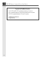
CAUTION
Spectrum Controls’ devices contain electronic components which are susceptible to damage from
electrostatic discharge. A static charge can accumulate on the surface of ordinary plastic wrapping or
cushioning material. If any Spectrum Controls’ device must be returned to Spectrum Controls, the
following packaging instruction must be followed:
PREFERRED: Use the original packaging material as supplied by Spectrum Controls. Place
the device inside the conductive plastic bag.
ACCEPTABLE: Wrap the device in some type of antistatic material. Antistatic plastic material
can be identified by its pink color, and can be obtained in sheet or bag form.
UNACCEPTABLE: Do not use ordinary plastic film, foam, or styrene chips ("popcorn" or
"peanuts"). These materials can accumulate charges in excess of 10,000 volts, resulting in
possible damage to the Spectrum Controls electronic device.
Antistatic (metallized plastic) bags can be obtained from the following manufacturers:
3M Company
Static, Inc.
Charles Water
(800-328-1368)
(800-782-8424)
(617-964-8370)
Type 2100 bag
8000 Series bag
CP-303 bag
i
SOI-120 OPERATOR INTERFACE MODULE USER MANUAL
LIMITED WARRANTY
Spectrum Controls warrants that its products are free from defects in material and
workmanship under normal use and service, as described in Spectrum Controls
literature covering this product, for a period of 1 year. Spectrum Controls’
obligations under this warranty are limited to replacing or repairing, at its option, at
its factory or facility, any product which shall, in the applicable period after
shipment, be returned to Spectrum Controls’ facility, transportation charges prepaid,
and which after examination are determined, to the satisfaction of Spectrum
Controls, to be thus defective.
This warranty shall not apply to any such equipment which shall have been repaired
or altered except by Spectrum Controls or which shall have been subject to misuse,
neglect or accident. In no case shall Spectrum Controls’ liability exceed the purchase
price. The aforementioned provisions do not extend the original warranty period of
any product which has either been repaired or replaced by Spectrum Controls.
ii
CONTENTS
UL AND CSA APPROVAL
The equipment described in this manual is now listed with Underwriters
Laboratories Inc. (UL) and the Canadian Standards Association (CSA). With this UL
listing (file number E180101) and CSA listing (file number LR 101622), this
equipment is suitable for use in Class I, Division 2, Groups A, B, C, and D
hazardous locations or non-hazardous locations only.
When installing this equipment, you must ensure that the ultimate enclosure is in
accordance with Class I, Division 2 wiring methods as described in the National
Electrical Code (ANSI/NFPA 70) and the Canadian Electrical Code. You must also
ensure that peripheral equipment is suitable for the location in which it is used.
Lastly, you must observe the warnings shown below. Failure to observe these
warnings can cause personal injury.
!
WARNING
EXPLOSION HAZARD
Substitution of components may impair suitability for
Class I, Division 2.
!
WARNING
EXPLOSION HAZARD
Do not connect or disconnect equipment while circuit
is live unless the area is known to be non-hazardous.
!
ATTENTION
Use only with a Class 2 power source limited to 30 Vdc
open circuit and 8 A short circuit.
iii
SOI-120 OPERATOR INTERFACE MODULE USER MANUAL
Copyright and TradeMark information:
SOI, SOI-SPS, and SOI-PRO are trademarks of Spectrum Controls, Inc.
IBM is a registered trademark of International Business Machines Corporation.
MS-DOS is a registered trademark of Microsoft Corporation.
© 1998 Spectrum Controls, Inc.
All rights reserved.
iv
CONTENTS
Contents
Chapter 1: Using this Manual ................. 1
Contents....................................................................... 1
Intended Audience........................................................ 2
Conventions ................................................................. 2
Related Publications ..................................................... 2
Chapter 2: Overview of SOI-120 .............. 3
General Information ..................................................... 4
Description ................................................................... 5
Keypad ......................................................................... 7
Mode Key Operations
MODE
......................................... 8
DIP Switches ................................................................ 9
Communications Port ................................................ 11
Compatibility ............................................................. 12
Programming the SOI-120 ......................................... 12
SOI-SPS Programming Software ................................ 12
Upload/Download Connections ................................. 12
Default Settings .......................................................... 13
Chapter 3: Initial Setup and
Mode Menu .......................................................... 15
Apply Power ............................................................... 16
v
SOI-120 OPERATOR INTERFACE MODULE USER MANUAL
Power-up Sequence ..................................................... 17
Mode Menu ................................................................ 18
Resetting the SOI-120 ................................................ 19
Setting Communication Parameters Manually ........... 20
Test Functions ............................................................ 21
Terminal Mode ........................................................... 21
Special Function -- Point Access/Display (P-A/D) ...... 23
Using the Simulate Mode ........................................... 25
Adjusting LED Backlighting Settings ......................... 26
Adjusting LCD contrast settings ................................. 27
Entering a New Master Security Code ........................ 28
Enabling / Disabling Scaling ...................................... 29
Chapter 4: Up/Downloading
Programs .............................................................. 31
Upload / Download DIP Switch Settings ................... 31
Upload / Down load Connections .............................. 32
Computer Setup ......................................................... 33
Chapter 5: RUNNING APPLICATIONS ..... 35
DIP Switch Setting ..................................................... 36
Application Documentation ....................................... 36
Bit Write Mode........................................................... 36
Screen Navigation ....................................................... 36
Screen Types ............................................................... 38
Menu and Sub-Menu Screens ..................................... 39
Security Screens .......................................................... 39
Data Display Screens .................................................. 40
Data Entry Screens ..................................................... 40
Recipe Screens ............................................................ 40
Alarm Screens ............................................................. 41
vi
CONTENTS
Chapter 6: INSTALLATION ............................ 43
Safety Guidelines ........................................................ 43
Operating Environment ............................................. 44
Enclosures .................................................................. 44
Equipment Required .................................................. 44
Clearances .................................................................. 44
Mounting Dimensions ............................................... 46
Cutout Template ........................................................ 47
Installation ................................................................. 48
Connecting Power ...................................................... 49
Chapter 7: Troubleshooting ............... 51
Troubleshooting Recommendations ........................... 52
Equipment Required .................................................. 52
Common Operating Problems ................................... 52
Error Messages ........................................................... 53
Communication Error Codes ..................................... 56
Using the Test Functions ............................................ 56
DIP Switch Test ......................................................... 57
Display Test................................................................ 58
Keyboard Test ............................................................ 59
Communication Port Test .......................................... 60
Display Control Test .................................................. 62
RAM Test ................................................................... 63
System Memory Test .................................................. 63
Program Memory Test................................................ 64
TXEN Test ................................................................. 64
Cleaning the Display Window .................................... 66
vii
SOI-120 OPERATOR INTERFACE MODULE USER MANUAL
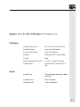
Appendix A: SOI-120 Specifications ..... 67
LCD Display .............................................................. 67
Keypad ....................................................................... 67
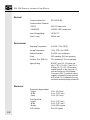
Electrical ..................................................................... 68
Environmental ............................................................ 68
Mechanical ................................................................. 68
Appendix B: SOI-120 Cable Diagrams .. 69
Appendix C: SOI-120 Panel Cutout ....... 71
Index ......................................................................... 73
viii
CHAPTER 1: USING
THIS
MANUAL
Chapter 1: Using this Manual
Read this chapter to familiarize yourself with the rest of the manual.
You will learn about:
•
Contents of this manual
•
Intended audience
•
Conventions
•
Related publications
Contents
The following table lists the contents of each chapter:
Chapter title
Purpose
Using this Manual
Provides an overview of the manual
Overview of the SOI-120
Contains a description of the SOI-120 and
accessory devices
Initial Setup and Mode Menu
Describes the initial setup of the SOI-120
using the mode menu functions
Up/Downloading Application Programs
Describes how to upload and download
application files between the SOI-120 and
a personal computer
Running Applications
Describes the basic screen types, and
describes the different function key
operations
1
SOI-120 OPERATOR INTERFACE USER MANUAL
Installation
Provides procedures for mounting the SOI-120,
including the wiring instructions and
recommendations
Troubleshooting and Maintenance
Provides assistance in identifying and correcting
common operating problems. Also provides cleaning
recommendations
Appendices
Contains supplementary information that may be
helpful. These include:
Appendix A, SOI-120 Specifications
Appendix B, SOI-120 Cable Diagrams
Appendix C, SOI-120 Panel Cutout
Intended Audience
No special knowledge is required to operate the SOI-120. If you are
installing the SOI-120, you must be familiar with the standard panel
cutout and installation techniques. If you are wiring the SOI-120, you
must be familiar with the electrical codes in your area (see inside front
cover).
You should be familiar with the SOI-120 Programming Software (SOISPS). Related publications are listed below.
Conventions
Keys that you press on the SOI-120 are enclosed in brackets [ ]. For
example: [NEXT] refers to the NEXT key on the SOI-120.
References to menus are initial cap followed by the word Menu. For
example: Special Menu, Main Menu, Other Menu.
All SOI-120 displays are shown inside a rectangular box.
1 Rst 2 Port 3 Test
4 PAD 5 Term 6 Other
Related Publications
The following publications may be helpful for additional reference.
Catalog number Publication
2
0300054-xx
0300050-xx
SOI-SPS Programming Software Manual for SOI products
SOI-260 Users Manual
CHAPTER 2: OVERVIEW
OF
SOI-120
Chapter 2: Overview of SOI-120
This chapter describes the SOI-120 and accessories. It contains these
sections:
Section
General Information
Description
Keypad
Mode Key Operations
MODE
DIP Switches
Communications Port
Compatibility
Programming the SOI-120
SOI-SPS Programming Software
Upload/Download Connections
Default Settings
Product Options
3
SOI-120 OPERATOR INTERFACE USER MANUAL
General Information
The SOI-120 interfaces with various types of programmable controllers
(PLCs). The SOI-120 allows operators to monitor and manipulate
process data on the plant floor.
RS-232 / RS-485 Selectable Communications Port.
The SOI-120 has a selectable RS-232/RS-485 port for communicating
with the PLC.
Note: SOI-120 DeviceNet units do not havve RS-485 functionality.
Memory Capability.
The communications protocol, configuration information, and userprogrammed screens are stored in nonvolatile memory, providing
storage for 244 screens.
Recipe Operations.
Recipe type functions allow operators to quickly modify blocks of data.
Download data to a maximum of 10 non-sequential register addresses
per screen. Link multiple recipe screens to download data to more than
10 addresses.
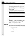
Flexible Function Key Operations.
Eight function keys provide a convenient way to trigger screen displays
and to manipulate data in the PLC (change field status).
Point-Access/Display Function.
Allows you to monitor or modify data registers in the PLC. Use this
function to set up and debug application programs, as well as monitor/
modify data registers directly.
4
CHAPTER 2: OVERVIEW
OF
SOI-120
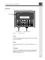
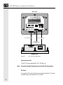
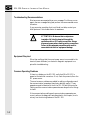
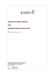
Description
The front panel of the SOI-120 terminal is shown below.
SOI 1SERIES
00
LED Indicator
RUN
Display Window
MENU
F1
F2
F3
F4
F5
F6
PREV
F7
F8
NEXT
Power Connector
Figure 2.1
MODE
1
2
3
4
5
6
CE
7
8
9
+/-
.
0
Communications Port
SOI-120 (front view)
Display
The 2 line by 20 character display uses high contrast LCD technology
with LED backlighting.
Keypad
The keypad is separated by color into easily identified groups or functions.
LED Indicator
A RUN LED in the upper left corner of the terminal indicates proper
operation of the SOI-120. This LED illuminates after the SOI-120
passes the self diagnostic tests.
5
SOI-120 OPERATOR INTERFACE USER MANUAL
5
Tx ENABLE
NC
COMMON
SHIELD
1
9
6
SW-1
SW-2
SW-3
SW-4
SW-5
SW-6
UPLOAD/
DOWNLOAD
MASTER SECURITY
MODE KEY
TERM MODE ENABLE
NOT USED
OPEN=RS232
CLOSED=RS485
OPEN - DISABLE
CLOSED - ENABLE
Communications Port
Power
18-30 VDC
200mA
max.
+VDC
RS232
RS485
PIN-6
PIN-7
PIN-8
PIN-9
COMM
Tx485Tx485+ / Rx232
Rx428- / Tx232
Rx485+
COMMON
E-GND
PIN-1
PIN-2
PIN-3
PIN-4
PIN-5
SPECTRUM
CONTROLS
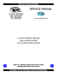
SOI SERIES 100
Back View
Power Connector
DIP Switch
(Behind Removable
Cover)
Bottom View
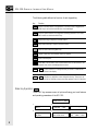
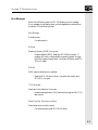
Figure 2.2
SOI-120 (back & bottom view)
Communications Port
The SOI-120 has a selectable RS-232 / RS-485 port.
Note: Units with DeviceNet Capability do not have RS-485 functionality.
DIP Switch
A six position DIP switch selects various operating settings. This switch
is located under a removable cover on the back.
6
CHAPTER 2: OVERVIEW
OF
SOI-120
Power Connector
The power connector is a non-removable, screw terminal block located
on the bottom of the unit. Connect 24 VDC to these terminals or use
an AC Adapter as an option.
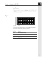
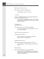
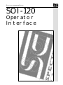
Keypad
Figure 2.3
MENU
F1
F2
F3
F4
F5
F6
PREV
F7
F8
NEXT
MODE
1
2
3
4
5
6
CE
7
8
9
+/-
.
0
Keypad
The SOI-120 uses a sealed membrane, tactile feedback keypad. The
keys are color coded to easily identify key functions.
Key Color
Function
Green
Movement/Operator Response
Light Gray
Display/Format Control
White
Numeric Entry
7
SOI-120 OPERATOR INTERFACE USER MANUAL
The following table defines the function of each keypad key.
Key
Function
MENU
Returns to the Main Menu of an application. If an alarm screen is triggered, the
MENU key is not functional until the alarm is acknowledged.
MODE
Accesses special features and configuration operating parameters. DIP switch
SW-3 enables or disables the MODE key.
PREV
Steps back through a sequence of linked screens.
NEXT
Steps forward through a sequence of linked screens.
CE
Clears an entire value during data entry.
+/-
Toggles a data entry value between positive or negative
.
Enters a decimal point.
Sends data to the controller. Data includes default values or data entered at the
keyboard. Also used to acknowledge alarm screens.
Mode Key Operations
0
9
Enters numbers 0 to 9 during data entry or selects a numbered item
shown on the display.
F1
F8
Displays any application screen assigned to the key. These keys can
also set or clear bits at eight consecutive registers in the PLC data field.
MODE
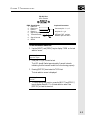
The MODE key accesses a menu of options allowing you to set features
and operating parameters of the SOI-120.
1 Rst 2 Port 3 Test
4 PAD 5 Term 6 Other
2
1
1 Reset SOI 120
2 Abort
4
1 Baud Rate 3 Parity
2 Data Bits 4 Exit
5
1 Chg Addr
2 By Pass
8
3
SOI-120 Diag Test
6
1 Half Dup 2 LF Enab
3 Cur Enab 4 Exit
1 Sim 3 Cont 5 Scale
2 BL 4 Mstr 6 Exit
CHAPTER 2: OVERVIEW
OF
SOI-120
Mode Menu
Select this option…
1 Reset
2 Com-Port
To perform this function
Performs a system reset.
1 Baud Rate
2 Data Bits
3 Parity
4 Exit
Specifies 300, 1200, 2400, 9600, 19200, 38400
Specifies 7 or 8 data bits.
Specifies even, odd or none parity
Exits and returns to the Mode Menu
3 Test
Performs a self-diagnostic test.
4 P-A/D
Access to P-A/D. Allows monitoring and
modification of data registers in the PLC.
5 Term
1 Half Dup
2 LF Enable
3 Cursor Enab
4 Exit
Switch between Half / Full Duplex
Enable line feeds
Turns cursor on or off
Exit to mode key menu
6 Other
1 Sim
Allows you to simulate (run) your application
program without being connected to a PLC.
Allows adjustment of the display LED
backlighting.
Allows adjustment of the display contrast.
Modifies the master security code of the SOI.
Converts controller values to engineering units.
Exits and returns to the Mode Menu.
2 BL
3 Cont
4 Mstr
5 Scale
6 Exit
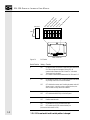
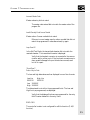
DIP Switches
The 6 position DIP switch allows you to enable or disable certain
functions. The DIP switch is accessed by removing the access cover on
the back.
9
pl
oa
d/
D
M
o
as
te wnl
r
oa
S
M
d
od ec
En
ur
e
a
i
Te Key ty E ble
rm
En na
in
ab ble
a
N
ot l M le
o
U
se de
C
En
om d
ab
m
le
En
ab
le
R
S23
2/
-4
85
SOI-120 OPERATOR INTERFACE USER MANUAL
U
Side View
1
2
3
4
5
6
ON=
OPEN
Back of SOI-120
Figure 2.4
DIP Switch
Switch Position Setting Function
1*
ON
OFF
2
10
ON position allows the transfer of application files between the
SOI-120 and a personal computer running SPS. All
communication between the SOI-120 and PLC is disabled.
The keypad is also disabled
OFF enables communication between the SOI-120 and a PLC
ON
ON enables the master code. Enabling the master code allows
any security code to be accessed or modified.
OFF
OFF disables the master code. Disabling the master code still
allows access to a security screen or special functions, but
does not allow security codes to be modified.
3
ON
OFF
ON enables the MODE key on the front panel
OFF disables the MODE key on the front panel.
4
ON
OFF
Enables terminal mode.
Disables terminal mode.
6
ON
ON enables the RS-485 communications port
OFF
OFF enables the RS-232 communications port.
(Not used on DeviceNet SOI-120)
* SOI-120 is reset each time this switch position is changed.
CHAPTER 2: OVERVIEW
OF
SOI-120
Communications Port
All communications are through a 9 pin connector on the bottom of the
SOI-120. The connector is both an RS-232 and RS-485 port, and is
selected by placing switch number 6 in the ON or OFF position.
SOI-120
(Bottom View)
1
2
6
RS-485
Selected
PIN#
1
2
3
4
5
6
7
8
9
3
7
4
8
5
9
Signal Name
Data Out Data Out +
Data In Data In +
Signal Ground
Transmit Enable
Not Used
Signal Ground
Shield
SOI-120
(Bottom View)
1
2
6
RS-232
Selected
Figure 2.5
PIN#
1
2
3
4
5
6
7
8
9
3
7
4
8
5
9
Signal Name
Not Used
Receive Data (RD)
Transmit Data (TD)
Not Used
Signal Ground
Not Used
Not Used
Not Used
Shield
Communications Port
Note: For Communications Port information on SOI-120 DeviceNet units,
please refer to Spectrum Controls Publication #0300142-xx, “DeviceNet
Communications Reference.”
11
SOI-120 OPERATOR INTERFACE USER MANUAL
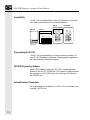
Compatibility
The SOI-120 is compatible with a variety of Spectrum Controls products. Shown below are some of the compatible devices.
SOI-260
SOI-SPS
SOI-200/250
SOI-120
Figure 2.6
Compatible Devices
Programming the SOI-120
The SOI-120 is programmed off-line using a personal computer running SOI-SPS Programming Software. Operating system upgrades are
also transferred using a personal computer.
SOI-SPS Programming Software
Use SOI-SPS software (Catalog No. SOI-SPS) to create application
screens for both the SOI-120 and SOI-260 Operator Interface products.
For a description of SOI-SPS, refer to the User Manual (Publication
No. 0300054-xx).
Upload/Download Connections
For programming and configuration, the SOI-120 is connected to your
computer’s RS-232 port.
12
CHAPTER 2: OVERVIEW
OF
SOI-120
SOI-120
Programming Terminal
Cable
(Catalog No. SCC-3)
Default Settings
The SOI-120 is preset at the factory with the following default:
Operating System
The SOI-120 is provided with a default application file. The application file displays a screen with a message:
*** SOI-120
*** Micro
Bul
2707 DTAM
No Program loaded
DIP Switch Settings
The SOI-120 is shipped with the following DIP Switch settings:
DIP Switch
Position
Default
Setting
Function
1
ON
Upload/Download enabled
2
OFF
Master Security disabled
3
ON
MODE key enabled
4
OFF
Terminal Mode disabled
5
OFF
Not used
6
OFF
RS-232 Communications enabled
13
SOI-120 OPERATOR INTERFACE USER MANUAL
Operating Parameters
The following operating functions are set using the SOI-120 menu
functions. Refer to Chapter 3.
14
Function
Parameter
Default Value
RS-S232
C-Port
Baud
Data Bits
Parity
9600
8
Even
Other
Simulate
Master Code
Scale
OFF
00000000
On
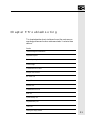
CHAPTER 3: INITIAL SETUP
AND
MODE MENU
Chapter 3: Initial Setup and Mode Menu
This chapter describes how to apply power to and then configure the
SOI-120 using the menu keys. Instructions on how to use the Simulate
mode to run an application are provided. This chapter contains the
following sections:
Section
Apply Power
Power-up Sequence
Mode Menu
Resetting the SOI-120
Setting Communication Parameters Manually
Test Functions
Terminal Mode
Point Access/Display (P-A/D)
Entering a New Master Security Code
Enabling / Disabling Scaling
Using the Simulate Mode
15
SOI-120 OPERATOR INTERFACE USER MANUAL
Apply Power
This section describes power connections for initial desktop setup and
programming. Refer to Chapter 6 for installation wiring instructions.
Note:
For power connections for SOI-120 DeviceNet units, please refer to
Spectrum Controls Publication #0300142-xx, “DeviceNet
Communications Reference.”
!
ATTENTION: Verify that the power is disconnected
from the power source before wiring. Failure to
disconnect power may result in electrical shock.
!
ATTENTION: Make sure that the supply voltage to
the SOI-120 is 18 to 30 volts DC. The incorrect
voltage may damage the SOI-120.
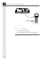
Connect the DC positive, DC common, and ground lines as shown
below.
Ea
r
th
Gr
DC ound
Co
mm
on
DC
Po
sit
ive
SOI-120
The SOI-120 performs a power-up sequence.
16
CHAPTER 3: INITIAL SETUP
AND
MODE MENU
Power-up Sequence
The power-up sequence is automatic, you do not have to respond to the
screens. The sequence depends upon DIP switch position #1 (upload /
download enable). The SOI-120 is shipped with this switch On.
Power-up Sequence (DIP Switch #1 On)
1. The SOI-120 verifies the system memory checksum, program
checksum, and system RAM. After the test is completed, the
result is displayed with the current DIP switch settings.
Memory Check: pass
2. The display is tested, every pixel of the display is turned on.
If all of the pixels do not turn on, the display may be defective.
3. SOI-120 information appears indicating the microprocessor
core firmware version and communication port settings (RS-232
or RS-485).
Operator Interface
Core: 2.01 RS-232
4. The SOI-120 waits for an application download.
Programming Mode
Waiting Up/Download
Power-up Sequence (DIP Switch #1 Off)
1. The SOI-120 verifies the system memory checksum, program
checksum, and system RAM. After the test is completed, the
result is displayed with the current DIP switch settings.
Memory Check: pass
DIP Switch: 101000
17
SOI-120 OPERATOR INTERFACE USER MANUAL
2. The display is tested, every pixel of the display is turned on.
If all of the pixels do not turn on, the display may be defective.
3. Operating system information appears indicating the firmware
release number and protocol being used.
SOI-120 (c) 1994
Rev: 1.00 Protocol
4. The first application screen displays. If the SOI-120 is being
powered up the first time you will see:
SOI-120
No Program Loaded
Mode Menu
Access the Mode Menu by pressing the [MODE] key. All other functions are halted when the menu is displayed.
Note:
DIP switch SW-3 must be in the On position or the [MODE] key will
not function.
The Mode Menu provides access to six functions:
1 Rst 2 Port 3 Test
4 PAD 5 Term 6 Other
Select a menu item by pressing the corresponding numeric key [1] - [6].
The menu structure is shown below:
18
CHAPTER 3: INITIAL SETUP
AND
MODE MENU
1 Rst 2 Port 3 Test
4 PAD 5 Term 6 Other
2
1
1 Reset SOI 120
2 Abort
3
1 Baud Rate 3 Parity
2 Data Bits 4 Exit
SOI-120 Diag Test
Configures SOI-120
Communications Port
4
5
1 Chg Addr
2 By Pass
P-A/D
Special
Controller Operations
Performs Functional
Tests
6
1 Half Dup 2 LF Enab
3 Cur Enab 4 Exit
Sets parameters for
Terminal Mode
1 Sim 3 Cont 5 Scale
2 BL 4 Mstr 6 Exit
1 Simulates Controller
Communications
2 LED Backlighting
3 Enables LCD Contrast
Adjustments
4 Sets Master Security
Code ①
5 Enables/Disables
Scaling
6 Exits to Mode Menu
① DIP switch position 2
must be ON (master
code enable).
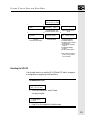
Resetting the SOI-120
Use the reset function to reset the SOI-120 after DIP switch changes or
a configuration change using the Mode Menu.
To reset the SOI-120:
1 Rst 2 Port 3 Test
4 PAD 5 Term 6 Other
1. From the Mode Menu, select 1 Reset.
You are prompted:
1 = Reset SOI-120
0 = Abort
2. Press [1] on the keypad to initiate the reset.
19
SOI-120 OPERATOR INTERFACE USER MANUAL
The SOI-120 resets. This has the same effect as turning the power on
and off. The SOI-120 performs the self-diagnostic tests and power-up
displays as described in the previous section.
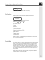
Setting Communication Parameters Manually
The Com-Port option in the Mode Menu lets you manually adjust the
communication port parameters. Normally these parameters are set
automatically from the programming software when an application is
downloaded.
1 Rst 2 Port 3 Test
4 PAD 5 Term 6 Other
Select Port from the Mode Menu.
This menu displays:
1 Baud Rate 3 Parity
2 Data Bits 4 Exit
Select an item by pressing the corresponding numeric key [1]-[4].
Baud Rate
Selecting Baud Rate displays the current baud rate.
Baud Rate 19200
“Next” to change
Press [NEXT] to select a new rate: 300, 1200, 2400, 4800, 9600,
19200, 38400.
Data Bits
Selecting Data Bits displays the current setting.
Data Bits 7
“Next” to change
Press [NEXT] to select either 7 or 8 bits.
Parity
Selecting Parity displays the current setting.
20
CHAPTER 3: INITIAL SETUP
AND
MODE MENU
Parity Even
“Next” to change
Press [NEXT] to select Even, Odd, or No parity.
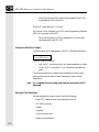
Test Functions
Selecting Test from the Other Menu displays the test screen:
SOI-120 Diag Test
< Test Selection >
Use the Test Menu to perform the following:
Reset DUT (Display Under Test)
DIP switch positions
Display
Keyboard
Communications port
Random Access Memory (RAM)
System memory
Program memory
Transmit enable
Refer to Chapter 7, Troubleshooting and Maintenance, for instructions
on how to perform these tests.
Terminal Mode
DIP switch position 4 on the SOI-120 enables the unit’s terminal mode
when ON. The terminal mode disables execution of the downloaded
program and enables the SOI to function as a terminal device. In the
terminal mode, the SOI displays any ASCII data received through the
communications port. The ASCII codes associated with the keys on the
SOI keypad are transmitted through the communications port when a
key is pressed.
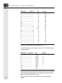
When using the SOI-120 in terminal mode, the keypad is mapped to
characters shown in the following table.
21
SOI-120 OPERATOR INTERFACE USER MANUAL
SOI-120 Key ............ ASCII 8-bit
Hex
Decimal
F1 ...................................................
F2 ...................................................
F3 ...................................................
F4 ...................................................
F5 ...................................................
F6 ...................................................
F7 ...................................................
F8 ...................................................
Menu ...............................................
Prev ................................................
Next ................................................
CE ........................................... <FF>
+/- ............................................... +/(.) ................................................. (.)
Enter ...................................... <CR>
9 .................................................... 9
8 .................................................... 8
7 .................................................... 7
6 .................................................... 6
5 .................................................... 5
4 .................................................... 4
3 .................................................... 3
2 .................................................... 2
1 .................................................... 1
0 .................................................... 0
91
92
93
94
95
96
97
98
85
82
80
0C
2B/2D
2E
D
39
38
37
36
35
34
33
32
31
30
145
146
147
148
148
149
150
151
133
130
128
12
43/45
46
13
57
56
55
54
53
52
51
50
49
48
* The MODE key sends no code but allows access to the P-A/D.
If the SOI-120 communications port is set up for 7-bits, the following
codes are different:
SOI-120 Key ....... ASCII 7-bit
Hex
Decimal
F1 ..............................................
F2 ..............................................
F3 ..............................................
F4 ..............................................
F5 ..............................................
F6 ..............................................
F7 ..............................................
F8 ..............................................
Menu ..........................................
Prev ...........................................
Next ...........................................
11 (DC1)
12 (DC2)
13 (DC3)
14 (DC4)
15 (NAK)
16 (SYN)
17 (ETB)
18 (CAN)
5 (ENQ)
2 (STX)
0 (NUL)
17
18
19
20
21
22
23
24
5
2
0
To activate the terminal mode, set DIP switch position 4 to the closed
(ON) position and reset the SOI. The display will then blank and be
ready to receive incoming ASCII data.
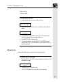
22
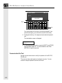
When you select TERM (menu selection 5), the following screen
appears:
CHAPTER 3: INITIAL SETUP
AND
MODE MENU
1 Half Dup 2 LF Enab
3 Cur Enab 4 Exit
Half Dup
Select this item to designate half duplex communications to and from
the host device.
The half duplex selection echoes (displays) to the screen the SOI keys
pressed.
LF Enab
Select this item to enable or disable the use of a Line Feed character each
time a Carriage Return character is received.
Cur Enab
Select this item to enable or disable a block cursor display.
Exit
Select this item to exit Term operation.
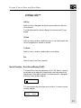
Special Function -- Point Access/Display (P-A/D)
The Special Menu item provides access to the P-A/D feature. A security
access code may be assigned in the application restricting access to the
Special Menu. After selecting Special, the following menu is displayed if
a Security Screen has been assigned:
* Security * Enter
:
This menu appears after entering a security code or if no security screen
has been assigned:
Point Access/Display
1 Chg Addr 2 Bypass
23
SOI-120 OPERATOR INTERFACE USER MANUAL
Note:
Below is a brief descriptions of the P-A/D feature.
The P-A/D feature is extremely useful when starting up, troubleshooting or directly accessing PLC data registers for quick monitoring or
modification.
This function allows access to all unrestricted PLC data registers. Use
the P-A/D feature to display and modify PLC data register values
directly. The NEXT and PREV keys scroll forward and backward
through the PLC register types.
Select a desired register type by scrolling through the choices and then
pressing the Enter key. The SOI-120 will then prompt you for the
register numbers. Type in the desired register number and press Enter.
To enter a numeric value or change a bit status you must press ENTER
once again to access the numeric or binary positions. Once accessing
these positions, enter the desired values and press ENTER to send to the
PLC.
Note:
After typing the desired register address, you must press ENTER twice to
access the numeric or binary positions.
Note:
To determine which data registers are supported, refer to SOI-SPS
programming software manual, PLC reference section and the selected
PLC operations manual.
When in the P-A/D mode, pressing the MENU key at any time will exit
you out of the P-A/D mode and return you to online operation.
!
24
ATTENTION: The P-A/D should be restricted only
to authorized personnel. The P-A/D will allow you to
read or write to all PLC data registers except for the
Input and Output registers. It is possible to change
PLC data which may alter the correct operation of the
SOI-120
CHAPTER 3: INITIAL SETUP
AND
MODE MENU
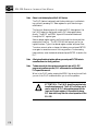
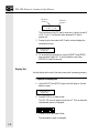
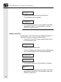
Using the Simulate Mode
The Simulate mode checks an application without having a controller
connected. All data that normally would be sent by the controller such
as data for a display is set to 0. Any ASCII data is set to (?). Selecting
Simulate from the Mode Menu will:
•
Halt communication between the SOI-120 and the controller.
•
Simulate Communication with a controller.
Disabling the Simulate mode resumes normal operation.
To simulate an application:
1. Download the application from the SOI-SPS software.
2. Enable the Simulate mode.
1 Rst 2 Port 3 Test
4 PAD 5 Term 6 Other
3. From the Mode Menu, select item 6.
The Other Menu appears:
1 Sim
2 BL
3 Cont
4 Mstr
5 Scale
6 Exit
4. Select item 1.
The Simulate enable screen displays:
Simul Enable
OFF (0)
0=Off
1=On
5. Press [1] to enable the Simulate mode.
6. Press [6] to exit the Other Menu and return to the Mode Menu.
7. From the Mode Menu, reset the SOI-120. Refer to page 18.
25
SOI-120 OPERATOR INTERFACE USER MANUAL
The SOI-120 displays a series of diagnostic tests, enters run
mode, loads the application and then displays the Mode Menu
of the application.
8. Run the program as you normally would. Notice that all display
registers show data as a set of zeroes.
Pressure = 0000 PSI
9. After verifying the operation of the program, press the [MODE]
key. All other functions are halted and the Mode Menu is
displayed.
10. Disable the Simulate mode.
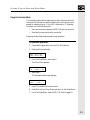
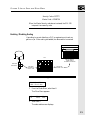
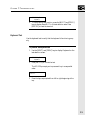
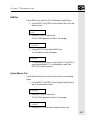
Adjusting LED Backlighting Settings
The BL screen allows you to adjust the amount of LED backlighting
required on the LCD display, which is adjustable in 4 steps.
Backlighting adjustments are useful if the ambient lighting conditions
are not bright enough to allow clear viewing of the display.
To enter a new Backlight setting:
1 Rst 2 Port 3 Test
4 PAD 5 Term 6 Other
1. From the Mode Menu, select item 6.
The Other Menu appears:
1 Sim
2 BL
3 Cont
4 Mstr
5 Scale
6 Exit
2. Press [2] to select the BL function.
The BL adjustment screen appears:
Press NEXT to adjust
Backlight (ENTER-EX)
26
CHAPTER 3: INITIAL SETUP
AND
MODE MENU
3. Press [NEXT] to select the desired backlight setting. Continuing
to press NEXT will cycle through the four settings.
4. Press [{arrow}] (enter key) to accept the desired setting.
Your are returned to the Other Menu.
5. Select item 6 to exit to the Mode Menu.
Adjusting LCD contrast settings
The contrast screen allows you to adjust the amount of contrast the
display uses for viewing purposes. Contrast is adjustable in four steps.
Contrast adjustments are useful for fine tuning the display in unique
lighting, temperature, or viewing conditions.
To enter a new Contrast setting:
1 Rst 2 Port 3 Test
4 PAD 5 Term 6 Other
1. From the Mode Menu, select item 6.
The Other Menu appears:
1 Sim
2 BL
3 Cont
4 Mstr
5 Scale
6 Exit
2. Press [3] to select the Contrast function.
The Contrast adjustment screen appears:
Press NEXT to adjust
Contrast (ENTER-EX)
3. Press [NEXT] to select the desired Contrast setting. Continuing
to press NEXT will cycle through the four settings.
4. Press
(enter key) to accept the desired setting.
Your are returned to the Other Menu.
5. Select item 6 to exit to the Mode Menu.
27
SOI-120 OPERATOR INTERFACE USER MANUAL
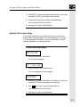
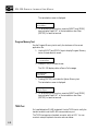
Entering a New Master Security Code
The Master Security code provides access to all security codes and allows
them to be modified. Two Master Security codes perform special
functions:
00000000 allows the operator to modify the existing Master code
without requiring entering the current code.
99999999 does not allow operator to modify security codes.
Changing of the Master Security code is through SPS software.
To enter a new Master Security code:
1 Rst 2 Port 3 Test
4 PAD 5 Term 6 Other
1. From the Mode Menu, select item 6.
The Other Menu appears:
1 Sim
2 BL
3 Cont
4 Mstr
5 Scale
6 Exit
2. Press [4] to select the Master Security code function.
The Master code entry screen displays:
Enter Current Master
Code: _
3. Enter the current code and press
.
You are prompted to enter the new code.
Enter New Master
Code: _
4. Enter a new code. The code must be 8 digits in length. If you
enter less than 8 digits the entry is padded with zeroes. For
example, an entry of 1234 is entered as 12340000.
Note:
28
Security codes can contain the wildcard character (?). Any entered value
will be seen as a match to the wildcard. You must make sure that the
Master Security code is different from security codes using wildcard
entries. Otherwise the Master Security code may be seen as a security
code. For example, if the:
CHAPTER 3: INITIAL SETUP
AND
MODE MENU
Security Code = 12??????
Master Code = 12368794
When the Master Security code above is entered, the SOI-120
interprets it as a security code.
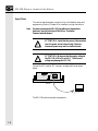
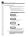
Enabling / Disabling Scaling
Use scaling to convert data from a PLC to engineering units such as
gallons or psi. When scaling is disabled, the values are not converted.
PLC
SOI-120 displays
scaled value of
16 Gallons Per Minute
Valve #1
Flow Rate
Transducer
Flow Rate
Transducer
Value = 510
Value From
Controller= 510
To enable or disable scaling:
1 Rst 2 Port 3 Test
4 PAD 5 Term 6 Other
1. From the Mode Menu, select item 6.
The Other Menu appears:
1 Sim
2 BL
3 Cont
4 Mstr
5 Scale
6 Exit
2. Select item 5.
The scale enable screen displays:
29
SOI-120 OPERATOR INTERFACE USER MANUAL
Scale Enable
0=Off
OFF(0)
1=On
3. Press [1] on the keypad to enable scaling or [0] to disable
scaling.
You are returned to the Other Menu.
4. Select item 6 to exit to the Mode Menu.
30
CHAPTER 4: UP/DOWNLOADING P ROGRAMS
Chapter 4: Up/Downloading Programs
This chapter describes how to transfer applications between the offline
programming software (SOI-SPS) and the SOI-120. It contains the
following sections:
Section
Upload / Download DIP Switch Settings
Upload / Down load Connections
Computer Setup
Upload / Download DIP Switch Settings
Before you can upload or download an application, you must verify that
the DIP switches are set as shown. To access the DIP switch, remove the
plug from the access hole on the back of the SOI-120 (align cover tabs
with notches in hole to remove). The SOI-120 is shipped without the
cover installed; you can find it in the hardware bag.
31
1
2
3
4
5
Po
rt
om
m
2C
-2
3
5/
RS
-4
8
Side View
RS
Up
loa
d/D
o
wn
loa
Ma
dE
st
na
er
ble
Se
cu
rit
Mo
yE
de
na
Ke
ble
yE
na
ble
Te
rm
ina
lM
od
eE
Un
na
us
ble
ed
SOI-120 OPERATOR INTERFACE USER MANUAL
6
ON=
OPEN
Back of SOI-120
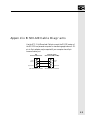
Upload / Down load Connections
To download an application to the SOI-120, you must:
•
connect a power supply (refer to Chapter 3).
•
connect the upload/download cable (SCC-3).
SOI-120
Refer to Chapter 3
for power connections.
Use Up/Download cable
(Catalog No. SCC-3)
To Computer
RS-232 Port
32
CHAPTER 4: UP/DOWNLOADING P ROGRAMS
Computer Setup
Upload and download functions are initiated from a personal computer
running the programming software SOI-SPS . Transfer functions
automatically occur at 9600 Baud.
After the transfer is complete, the SOI-120 Baud rate is set to the
parameters defined by the application program residing in the SOI-120.
Refer to the SOI-SPS Programming Software Manual for additional
instructions.
33
SOI-120 OPERATOR INTERFACE USER MANUAL
34
CHAPTER 5: RUNNING APPLICATIONS
Chapter 5: RUNNING APPLICATIONS
This chapter describes screen types and operating procedures that are
common to most applications. It contains the following sections:
Section
DIP Switch Settings
Application Documentation
Bit Write Mode
Screen Types
Screen Navigation
Menu and Sub-Menu Screens
Security Screens
Data Display Screens
Data Entry Screens
Recipe Screens
Alarm Screens
35
SOI-120 OPERATOR INTERFACE USER MANUAL
DIP Switch Setting
Before running an application, verify that the DIP switch position #1 is
in the OFF position. This enables communication with the controller.
Refer to DIP switch description in Chapter 2, Overview of the SOI-120.
Application Documentation
It is the responsibility of the application designer to document the
operation of an application program. This chapter only provides basic
guidelines. Before running an application, you should understand what
processes are being controlled and monitored.
!
ATTENTION: The function keys of the SOI-120
can be assigned different functions depending upon
the application. The application designer must
document these functions. Make sure you
understand any function key operations prior to
operating the SOI-120. Failure to do so may result in
unintended operation.
Bit Write Mode
The application designer can assign the function keys [F1] to [F8] to set
or clear a bit at a controller address. This bit may control a variety of
processes. It is the responsibility of the application designer to document the use of the Bit Write mode function keys. Refer to Chapter 2,
Overview of the SOI-120, for details on F1 through F8 operation.
Screen Navigation
The SOI-120 provides a variety of options for changing the screen
displays:
36
•
Screen links
•
Advisor option
•
Function keys
CHAPTER 5: RUNNING APPLICATIONS
Screen Links
Use the [NEXT] and [PREV] keys to step backward and forward
through this sequence.
Main Menu and sub-menu screens list screens that can be accessed by
pressing the assigned numeric key [0] through [9]. A typical Main
Menu screen provides links to individual screens or sub-menus:
1 Pump
3 Tank Status
2 Mixer Status 4 Recipe
In the example above, pressing [2] at the Main Menu displays the status
of a holding tank. Pressing [4] displays a sub-menu of the recipe screen
options.
Advisor Option
Applications can allow screen changes that are controlled by a PLC.
When the logic controller writes a valid screen number to a specified
Advisor register, the corresponding screen is displayed. The controller
can initiate a screen change based upon a variety of inputs to the controller. For example, a pressure limit switch can be used to initiate the
display of a pressure control screen. It is the responsibility of the application designer to document when and what screen changes may occur.
Function Keys
An application designer can link function keys [F1] through [F8] to
individual screens (except alarm screens). Pressing an assigned function
key displays the function key number for approximately 0.5 seconds and
then the assigned screen. It is the responsibility of the application
designer to document the operations assigned to function keys. There
are two function key modes:
•
Auto Return
•
Continue
37
SOI-120 OPERATOR INTERFACE USER MANUAL
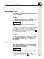
Auto Return
Auto return function keys return to the initial display after the linked
screen is executed. For example, assume that an application is displaying screen #6 and an auto return function key [F3] is linked to a recipe
screen #10. When [F3] is pressed, the recipe screen #10 is displayed.
After the operator downloads a new recipe on screen #10, the initial
screen #6 is displayed.
The following table describes when the return to initial screen occurs.
Function Key linked to: Returns to initial screen after:
Data Display screen
[Return], [PREV], or [NEXT] keys are pressed
Data Entry screen A value is entered of [Return], [PREV], or [NEXT] keys are pressed*
Recipe screen
Recipe data is downloaded or [PREV] or [NEXT] keys are pressed*
* [PREV] or [NEXT] keys abort the operation.
Continue
Continue function keys do not return to the initial display but remain
at the linked screen. For example, assume that an application is displaying screen #3 and a “continue” function key [F2] is linked to a data
entry screen #5. When [F2] is pressed, the data entry screen #5 is
displayed. The application continues from screen #5.
Screen Types
Application screens can have a variety of appearances. The SOI-120 can
display six types of screens.
38
•
Menu and Sub-menu Screens
•
Security Screens
•
Data Display Screens
•
Data Entry Screens
•
Recipe Screens
CHAPTER 5: RUNNING APPLICATIONS
•
Alarm Screens
Menu and Sub-Menu Screens
Menus and sub-menus provide a convenient method of accessing a large
number of display screens.
Main Menu
Every application has a Main Menu screen. The Main Menu is the first
application screen displayed after an initial power-up or reset.
1 Pump
3 Tank Status
2 Mixer Status 4 Recipe
The Main Menu provides access to the next level of screen sand submenus.
To access the Main Menu, press the [MENU] key. Pressing this key at
any time displays the Main Menu. The only time the Main Menu will
not be displayed is when an alarm screen has been triggered but not
,
acknowledged. You must acknowledge alarm screens by pressing
before another screen can be displayed.
Sub-Menus
Sub-menu screens function like the Main Menu. The only difference is
that you must navigate through the other screens or use assigned function keys to access the sub-menus. Refer to the previous section for
more information.
Security Screens
Security screens limit access to parts of an application. Although that
text on a security screen may be changed by the application designer,
many applications will use the default text:
*RESTRICTED ACCESS*
ENTER CODE:
A security code is a series of 1 to 8 digits. Each security screen can have
up to 3 code entries. Entering any one of the codes provides access.
To enter a security code, use the number keypad. An asterisk (*) is
after the entire code is
displayed for each number entered. Press
entered.
39
SOI-120 OPERATOR INTERFACE USER MANUAL
If a valid security code has been entered, the next linked screen is
displayed. If an invalid security code is entered, an error message
appears. Once the error condition is acknowledged by pressing
[NEXT], you can re-enter the code or return to the Main Menu.
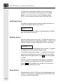
Data Display Screens
Data display screens show either the actual or scaled value that is contained in a data register location within the PLC.
Pump 1 Pressure = 150 PSI
Counter = 5
Data displays are updated at different intervals depending on the application and the size of the network.
Data Entry Screens
Data entry screens contain an entry field. The length and format of the
data entry field depends upon the application designer. In addition, the
application designer can place a data display field on the same screen:
Temp = 120 Deg F
Enter New Temp:
The data entry field must always appear last on the screen. The application designer cannot place text after a data entry field.
To enter data, use the numeric keypad. To modify an entry, press the
clear entry key [CE] and re-enter value. Press the [+/-] key to toggle
after the entire value
between positive and negative values. Press
is entered.
Data entry screens can have a default value appear in the data entry
field. A flashing cursor identifies the first digit of the default value.
Pressing
writes the default to the controller or you can enter a
different value by pressing the [CE] key.
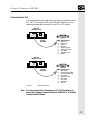
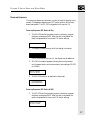
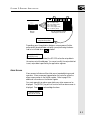
Recipe Screens
Recipe screens allow the SOI-120 to write multiple data register values
to the PLC at the same time. Recipe screens can also be linked so that
more than one recipe is downloaded.
40
CHAPTER 5: RUNNING APPLICATIONS
SOI 2SERIES
00
RUN
Download Recipe 323?
Press ENTER to send
F1
F2
MENU
MODE
F3
F4
F5
F6
PREV
CE
F7
F8
NEXT
+/-
1
2
3
4
5
6
7
8
9
.
0
T1:14.2 (Timer Value)
R1:30 = 0 (Integer Value)
R2:31 = 100 (Integer Value)
T2:15.1 (Timer Value)
R3:200 = 500 (Integer Value)
B1:10 = 10 (Binary Value)
SOI-120 Downloads Multiple
Data Registers to the PLC
Operator
Initiates
Controller Modifies Process
Using New Recipe Data
Depending upon the application designer, recipe screens will either
automatically download data or display a prompt allowing the downis pressed.
load to be initiated when
Download Recipe 323?
Press ENTER to send
Once the download is initiated, the SOI-120 writes the recipe data to
the various controller addresses. You cannot modify the recipe data that
is sent, recipe data is specified by the application engineer.
Alarm Screens
Alarm screens indicate conditions that are not expected during normal
operation. Alarm screens are triggered when the controller writes the
alarm screen number to the Advisor register. Refer to page 35 for
additional information on the Advisor register.
You must respond to an alarm screen before any other screens can be
displayed. The [MENU] key will not function while an alarm screen is
to acknowledge the alarm.
displayed. Press
Conveyor Overload
PRESS ENTER TO CLEAR
41
SOI-120 OPERATOR INTERFACE USER MANUAL
42
CHAPTER 6: INSTALLATION
Chapter 6: INSTALLATION
This chapter contains the following sections:
Section
Safety guidelines
Operating Environment
Enclosures
Equipment required
Clearances
Mounting Dimensions
Cutout Template
Installation
Connecting AC Power
Safety Guidelines
Install the SOI-120 terminal using publication NFPA 70E, Electrical
Safety Requirements for Employee Workplaces as a guide.
In addition, grounding is an important safety measure in electrical
installations. A source for grounding recommendations is the National
Electrical Code published by the National Fire Protection Association of
Boston, Massachusetts.
Refer to the inside front cover of this manual for additional guidelines.
43
SOI-120 OPERATOR INTERFACE USER MANUAL
Operating Environment
The SOI-120 is rated for operating temperature range of 32 to 131°F (0
to 55°C). The storage temperature range is -4 to 158°F (-20 to 70°C).
The humidity rating is 5 to 95% relative humidity (non-condensing).
If you are using a DC power supply, check the environmental ratings of
the supply.
Enclosures
The SOI-120 must be mounted in a panel or enclosure to protect the
internal circuitry. The SOI-120 meets NEMA Type 4, 12, 13 ratings
only when mounted in a panel or enclosure with the equivalent rating.
Allow enough spacing within an enclosure for adequate ventilation. For
some applications, you may have to consider heat produced by other
devices within a panel. The ambient temperature around the terminal
must be maintained between 32° and 131°F (0° to 55°C).
Make sure that provisions are provided for accessing the back panel of
the terminal for wiring, routine maintenance, and troubleshooting.
Equipment Required
Other than the tools required to make the panel cutout, the tools
required for installation are:
•
7mm (M4) deep well socket wrench or nut driver
•
small slotted screwdriver
•
torque wrench (in. / lbs.)
The SOI-120 is tightened against the panel with six self-locking nuts.
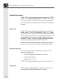
Clearances
Make sure that you leave adequate room, as shown in Figure 6.1, for
mounting, air flow, cabling, and access to DIP switches.
44
CHAPTER 6: INSTALLATION
Leave 3 inches (76.2 mm) for
Mounting, Air Flow, and
access to DIP Switches.
Leave 3 inches (76.2 mm) for
communications port connector.
Figure 6.1
Recommended Clearances
45
SOI-120 OPERATOR INTERFACE USER MANUAL
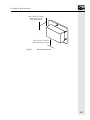
Mounting Dimensions
Figure 6.2 shows the mounting dimensions of the terminal.
Back View
5.4
(137.2)
3.9
(99.1)
6.9
(175.3)
Bottom View
5.4
(137.2)
1.8
(45.7)
Figure 6.2
46
Mounting Dimensions in Inches (Millimeters)
CHAPTER 6: INSTALLATION
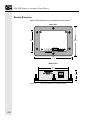
Cutout Template
A cutout template (actual to scale dimensions) is provided in Appendix
C to mark the cutout dimensions. Figure 6.3 is intended solely as a
reference copy; please do not remove this page from the manual.
6.08 in
3.04 in
3.97 in
3.04 inch = 77.22 mm
6.08 inch = 154.43 mm
3.97 inch = 100.84 mm
3.86 inch = 98.04 mm
4.55 inch = 115.57 mm
5.50 inch = 139.70 mm
0.69 inch = 17.53 mm
0.29 inch = 7.37 mm
3.04 in
.187 in dia
6 places
SOI-120
Panel Cut-Out
4.55 in
3.86 in
.69 in
.29 in
.29 in
5.50 in
Figure 6.3
Note:
Panel cutout Dimensions in Inches
This illustration is NOT TO SCALE. Refer to Appendix C for the SOI120 cutout template.
47
SOI-120 OPERATOR INTERFACE USER MANUAL
Installation
To install the SOI-120 Terminal:
!
ATTENTION: Disconnect all electrical power from
the panel before making cutout.
Make sure that area around panel cutout is clear.
Take precautions so that metal cuttings do not enter
any components that may already be installed in
panel.
Make sure that no objects are inserted or fall into the
terminal through the ventilation slots or DIP switch
access hole.
Failure to follow this warning may result in personal
injury or damage to the panel components.
1. Cut an opening in the panel as shown in Figure 6.3. Use the
full size cutout located inside the back cover of this manual.
Remove any sharp edges or burrs.
2. Make sure the neoprene sealing gasket is properly positioned on
the SOI-120. This gasket forms a compression type seal. Do
not use sealing compounds.
3. Place the SOI-120 in the panel cutout.
!
48
ATTENTION: Mounting must be tightened to a
torque of 4 inch pounds to provide a proper seal and
to prevent potential damage to the SOI-120.
Spectrum Controls assumes no responsibility for
water or chemical damage to the SOI-120 or other
equipment within the enclosure because of improper
installation.
CHAPTER 6: INSTALLATION
4. Install the six self locking mounting nuts hand tight.
5. Alternately tighten the mounting nuts until the SOI-120 is held
firmly against the panel. Tighten mounting nuts to a torque of
4 inch-pounds. Do not overtighten nuts.
Connecting Power
The SOI-120 accepts power supply voltages from 18 to 30 VDC (use
isolated DC power supply capable of providing at least 200 mA).
Connect the SOI-120 directly to the power source or use an AC
adapter, depending upon the source voltage.
Note:
For power connections for SOI-120 DeviceNet units, please refer to
Spectrum Controls Publication #0300142-xx, “DeviceNet
Communications Reference.”
!
ATTENTION: Verify that the power is disconnected
from the power source before wiring. Failure to
disconnect power may result in electrical shock.
Make sure that the supply voltage to the SOI-120 is
18 to 30 volts DC. The incorrect voltage may
damage the SOI-120. Do not overtighten the power
connector screw terminals. Overtightening the
terminals may damage the SOI-120.
To connect the SOI-120 to a power source:
1. Make sure the voltage source is not turned on.
2. User AWG#16 or #14 stranded wire to connect the SOI-120
screw terminals to the DC power source (see below).
Note:
The terminal block on the SOI-120 is not removable.
49
Ea
rt
hG
DC rou
Co nd
m
DC mon
Po
sit
ive
SOI-120 OPERATOR INTERFACE USER MANUAL
SOI-120
Use AWG#16 or #14
Stranded Wire
To 24 VDC Power Source
Figure 6.4
DC Power Connections
3. Connect communications cabling.
4. Apply voltage and verify the SOI-120 power-up sequence.
50
CHAPTER 7: TROUBLESHOOTING
Chapter 7: Troubleshooting
This chapter describes how to isolate and correct the most common
operating problems and routine maintenance tasks. It contains these
sections:
Section
Troubleshooting Recommendations
Equipment Required
Common Operating Problems
Error Messages
Communication Error Codes
Using the Test Functions
DIP Switch Test
Display Test
Keyboard Test
Communication Port Test
RAM Test
System Memory Test
Program Memory Test
TXEN Test
Cleaning the Display Window
51
SOI-120 OPERATOR INTERFACE USER MANUAL
Troubleshooting Recommendations
Most errors are accompanied by an error message. Find the error message in the error message listing and perform the recommended corrective action.
If you encounter a problem that is not listed in a table, contact your
local Spectrum Controls distributor for assistance.
!
ATTENTION: Make sure that no objects are
inserted or fall into the terminal through the
ventilation slots or DIP switch access hole. Always
disconnect power when checking wiring connections.
Failure to take adequate precautions may result in
severe electrical shock or equipment damage.
Equipment Required
Other than verifying that the correct power source is connected to the
terminal (use a voltmeter), no electronic diagnostic equipment is required for troubleshooting.
Common Operating Problems
If there is no display on the SOI-120, verify that 18 to 30 VDC is
present at the terminal connectors. If not, check the power to/from the
DC power source.
The most common problems are related to cabling configurations and
the communication parameters (baud rate, data bits, parity). These
parameters must be identical for both the SOI-120 and the controller.
Cabling and the communications parameters are always the first things
to check.
If the communications cabling and communications parameters are
correct, perform the diagnostic tests (described in this chapter) to rule
out any non-functioning features of the SOI-120.
52
CHAPTER 7: TROUBLESHOOTING
Error Messages
Refer to the following when the SOI-120 displays an error message.
Error messages, the probable cause, and the suggested corrective action
are shown in the following format:
Error Message
Probable cause
Corrective action
ROM fail
Read-only memory (ROM) is incorrect
Possible defective ROM. Reset the SOI-120 and recheck. If
problem still exists, re-download the operating system through
the SPS programming software. If problem still exists, send SOI120 in for repair.
RAM fail
RAM memory failed write or read test
Reset the SOI-120 and re-check. If problem still exists, send
SOI-120 in for repair.
*.CFG file invalid
Application file checksum is incorrect
Possible bad application file. Download the program file (.CFG)
and recheck.
Watch Dog Fault Press key to continue
Watch dog timer not within specs.
If problem persists, send SOI-120 for repair.
53
SOI-120 OPERATOR INTERFACE USER MANUAL
Watch Dog Fault Press Key to Reset
Watch dog timer timed out or pass bits not set
If problem persists, send unit in for repair.
PLC not found
This error message displays after a 2-second interval of attempting to
establish communications with the PLC.
Communications not established with the PLC. Check cabling
and communications parameters to verify that the PLC matches
those of the SOI-120
Communication Loss
Press ENTER to reset
Communication with the PLC was lost after 16 attempts
Check the cabling between the SOI-120 and the PLC. Check
PLC operating conditions.
Com Error Code: nnH Press ENTER to reset
Communication error code (nn)
Received a controller error code. Refer to next section for
communication error code explanations.
Attempted Invalid Screen Access
Illegal or unprogrammed screen type detected (.CFG file error)
Check the program (.CFG) file and download. Check linking
and so on.
Not Programmable
Master code is 99999999 and is not user-programmable.
A master code number of 99999999 may not be programmed.
Download a new, valid master code number using SOI-series
Programming Software (SPS).
54
CHAPTER 7: TROUBLESHOOTING
Incorrect Master Code
Master code entry did not match
The master code entered did not match the master code of the
program file.
Invalid Security Code Access Denied
Master code or 3 screen codes did not match.
Either an incorrect master security code or a coded that did not
match the programmed 3 codes was entered; try again.
Loop Error XX
In the Self-Test Mode, the transmitted character did not match the
received character. The transmitted character is displayed.
Verify that the loopback connector is connected to the communication and/or printer ports. If the loop-back connectors are in
place, possible damage to the port drivers has occurred; send
unit in for repair.
**Input Error**
Press a Key to Cont.
The low and high data values are then displayed in one of two formats:
Low Lim
XXXXXX
High Lim
XXXXXX
Low XXXXXX
High XXXXXX
The data entered is not within the programmed limits. The Low and
High limits, as programmed, are displayed.
Verify that the displayed limits are as programmed for the entry
field. Re-enter data within the entry limits.
READ ONLY
The controller location is not configured for a Write function (P-A/D
function).
55
SOI-120 OPERATOR INTERFACE USER MANUAL
Verify that the controller location being accessed by the P-A/D
is acceptable for Write functions.
Prog SW/0I Version Mismatch - OI Locked
An incorrect unlock code sent by the SOI-series Programming Software
(SPS). Wrong version of the SPS.
Verify that the version of SPS is compatible for the controller
type supported by the SOI-120.
Communication Error Codes
Communication error codes appear on the SOI-120 display as follows:
Com Error Code: nnH
Press ENTER to Reset
The error code is in the form:
•
nnH for PLC controllers that do not show extended error codes.
•
X nnH for PLC controllers. The X indicates an extended error
code.
The communication error codes provide valuable information when
other symptoms either have not been discovered or have not been
understood.
Note: For a complete list of error codes, consult the user manuals for the PLC
being used.
Using the Test Functions
Use the test selection screen to test or check the following:
Reset DUT (resets terminal, terminates test function)
DIP switch positions
Display
Keyboard
Communications port
Random Access Memory
56
CHAPTER 7: TROUBLESHOOTING
System memory
Transmit enable
To access the test functions:
1. Access the test functions from the Main Menu.
1 Rst 2 Port 3 Test
4 PAD 5 Term 6 Other
2. Select item 3 from the Main Menu to display the test selection
screen:
SOI-120 Diag Test
< Test Selection >
3. Use the [NEXT] and [PREV] keys to scroll through the test
options. Display the test you want to perform.
4. Press [ENTER] to initiate the test.
5. To terminate the test, press the [NEXT] and [PREV] keys to
display Reset DUT in the test selection area. Press [ENTER] to
reset the terminal.
DIP Switch Test
Use the DIP switch test to verify the DIP switch positions.
To perform the DIP switch test:
1. Use the [NEXT] and [PREV] keys to display DIP Switch on the
test selection screen.
SOI-120 Diag Test
Dipswitch
2. Press [ENTER] to initiate the test.
The SOI-120 displays the current DIP switch settings.
57
SOI-120 OPERATOR INTERFACE USER MANUAL
DIP Switch
Position 1
DIP Switch
Position 6
DIP Switch: 0 1 1 0 0 0
0 = OFF 1 = ON
The 6 positions of the DIP switch are shown in binary format (0
= Off, 1 = On). The leftmost value represents DIP switch
position #1.
3. Press any key to terminate the DIP switch test and display the
test selection screen:
SOI-120 Diag Test
Display Test
4. To terminate the test function, press the [NEXT] and [PREV]
keys to display Reset DUT in the test selection area. Press
[ENTER] to reset the terminal.
Display Test
Use the display test to verify that each screen pixel is operating properly.
To perform the display test:
1. Use the [NEXT] and [PREV] keys to show Display on the test
selection screen.
SOI-120 Diag Test
Display Test
2. Press [ENTER] to initiate the test.
The SOI-120 turns all pixels on and then off. Then an alternate
checkerboard pattern is displayed:
3. Press any key to terminate the test.
The test selection screen is displayed.
58
CHAPTER 7: TROUBLESHOOTING
SOI-120 Diag Test
Keyboard
4. To terminate the test function, press the [NEXT] and [PREV]
keys to display Reset DUT in the test selection area. Press
[ENTER] to reset the terminal.
Keyboard Test
Use the keyboard test to verify that the keyboard is functioning properly.
To perform the keyboard test:
1. Use the [NEXT] and [PREV] keys to display Keyboard on the
test selection screen.
SOI-120 Diag Test
Keyboard
2. Press [ENTER] to initiate the test.
The SOI-120 prompts you to press each key in a sequential
order.
Press “F1”
3. Press the keys as prompted from left to right beginning at the
top.
59
SOI-120 OPERATOR INTERFACE USER MANUAL
SOI 1SERIES
00
RUN
Display Window
Begin
MENU
F1
F2
F3
F4
F5
F6
PREV
F7
F8
NEXT
MODE
1
2
3
4
5
6
CE
7
8
9
+/-
.
0
End
You must press all of the keys in the order prompted. If you
press the wrong key, you must start over with the first key.
4. Pressing the last key in the sequence terminates the keyboard
test.
The test selection screen is displayed.
SOI-120 Diag Test
Comm Port
5. To terminate the test function, press the [NEXT] and [PREV]
keys to display Reset DUT in the test selection area. Press
[ENTER] to reset the terminal.
Communication Port Test
Use the communications test to verify the operation of the RS-232 /
RS-485 port.
The communications test requires a loopback connector. You can
construct a simple loopback connector as follows:
60
CHAPTER 7: TROUBLESHOOTING
RS-232 Port
9-Pin Female
1
2
6
PIN#
1
2
3
4
5
6
7
8
9
3
7
4
8
5
9
Signal Name
Data Out
Receive Data (RD)
Transmit Data (TD)
Loopback Connector
Connects pins 2
3
Signal Ground
Shield
RS-485 Port
9-Pin Female
1
2
6
PIN#
1
2
3
4
5
6
7
8
9
Signal Name
Data Out
Data Out +
Data In Data In +
Signal Ground
Transmit Enable
3
7
4
8
5
9
Loopback Connector
Connects pins 1
and pins 2
3
4
Signal Ground
Shield
To test the communications port:
1. Use the [NEXT] and [PREV] keys to display Comm on the test
selection screen.
SOI Diag Test
Comm Test
2. Press [ENTER] to initiate the test.
The SOI-120 will continuously send out and receive a message
at the same port. The message is SOI-120 self looping serial test
ABCDEFGHIJKLMNOPQRSTUVWXYZ0123456789.
61
SOI-120 OPERATOR INTERFACE USER MANUAL
SOI-120 self looping
serial test ABCD
3. Press any key to terminate the communications test.
The test selection screen is displayed.
SOI-120 Diag Test
Display Control
4. To terminate the test function, press the [NEXT] and [PREV]
keys to display Reset DUT in the test selection area. Press
[ENTER] to reset the terminal.
Display Control Test
Use the Display Control Test to verify that the Backlighting and Contrast adjustments cycle through each respective setting.
1. Use the [NEXT] and [PREV] keys to display Display Control
on the test selection screen.
SOI-120 Diag Test
Display Control
2. Press [ENTER] to initiate the test.
The SOI-120 displays and cycles through both the Backlighting
and Contrast settings with the following screens displayed.
*******************
Display Brightness
*******************
Display Contrast
3. Once the test is complete, the next test selection is displayed.
SOI-120 Diag Test
Ram Test
4. To terminate the test function, press the [NEXT] and [PREV]
keys to display the Reset DUT in the test selection area. Press
[ENTER] to reset the SOI.
62
CHAPTER 7: TROUBLESHOOTING
RAM Test
Use the RAM test to verify the SOI-120 Random Access Memory.
1. Use the [NEXT] and [PREV] keys to display RAM on the test
selection screen.
SOI-120 Diag Test
Ram Test
2. Press [ENTER] to initiate the test.
The SOI-120 displays either a Pass or Fail message.
RAM: pass
Press ENTER
3. Pressing [ENTER] terminates the RAM test.
The test selection screen is displayed.
SOI-120 Diag Test
System Memory
4. To terminate the test function, press the [NEXT] and [PREV]
keys to display Reset DUT in the test selection area. Press
[ENTER] to reset the terminal.
System Memory Test
Use the System Memory test to verify the checksum of the operating
system.
1. Use the [NEXT] and [PREV] keys to display System Memory
test on the test selection screen.
SOI-120 Diag Test
System Memory
2. Press [ENTER] to initiate the test.
The SOI-120 displays either a Pass or Fail message.
System Memory: pass
Press ENTER
3. Pressing [ENTER] terminates the System Memory test.
63
SOI-120 OPERATOR INTERFACE USER MANUAL
The test selection screen is displayed.
SOI-120 Diag Test
Program Memory
4. To terminate the test function, press the [NEXT] and [PREV]
keys to display Reset DUT in the test selection area. Press
[ENTER] to reset the terminal.
Program Memory Test
Use the Program Memory test to verify the checksum of the current
application file.
1. Use the [NEXT] and [PREV] keys to display Program Memory
test on the test selection screen.
SOI-120 Diag Test
Program Memory
2. Press [ENTER] to initiate the test.
The SOI-120 displays either a Pass or Fail message.
System Mem: pass
Press ENTER
3. Pressing [ENTER] terminates the System Memory test.
The test selection screen is displayed.
SOI-120 Diag Test
Toggle Cntrl Signal
4. To terminate the test function, press the [NEXT] and [PREV]
keys to display Reset DUT in the test selection area. Press
[ENTER] to reset the terminal.
TXEN Test
Only available when RS-485 is selected. Use the TXEN test to verify the
transmit enable line at the RS-485 communications port.
The TXEN test requires a loopback connector with an LED. You can
construct a simple loopback connector as shown below:
64
CHAPTER 7: TROUBLESHOOTING
RS-485 Port
9-Pin Female
1
2
6
PIN#
1
2
3
4
5
6
7
8
9
Signal Name
Data Out
Data Out +
Data In Data In +
Signal Ground
Transmit Enable
Signal Ground
Shield
3
7
4
8
5
9
Loopback Connector
Connects pins 1
LED
750 Ω
and pins 2
3
4
LED and 750Ω resistor
between pins 2-4 and 6
To test the transmit enable line:
1. Use the [NEXT] and [PREV] keys to display TXEN on the test
selection screen.
SOI-120 Diag Test
Toggle Cntrl Signal
2. Press [ENTER] to initiate the test.
The LED should flash at approximately 1 second intervals
indicating that the transmit enable line is functioning properly.
3. Pressing [ENTER] terminates the TXEN test.
The test selection screen is displayed.
SOI-120 Diag Test
Reset DUT
4. To terminate the test function, press the [NEXT] and [PREV]
keys to display Reset DUT in the test selection area. Press
[ENTER] to reset the terminal.
65
SOI-120 OPERATOR INTERFACE USER MANUAL
Cleaning the Display Window
To clean the display window:
ATTENTION: Use of abrasive cleaners or solvents
may damage the window. Do not scrub or use
brushes. Some types of paper towels may scratch the
window; use only a soft sponge or cloth.
1. Disconnect power from the terminal at the power source.
2. Using a clean sponge or a soft cloth, clean the display with a
mild soap or detergent.
3. Dry the display with a chamois or moist cellulose sponge to
avoid water spots.
Removing Paint and Grease
Remove fresh paint splashes and grease before drying by rubbing lightly
with isopropyl alcohol. Afterward, provide a final wash using a mild
soap or detergent solution. Rinse with clean water.
66
APPENDIX A: SOI-120 SPECIFICATIONS
Appendix A: SOI-120 Specifications
LCD Display
Character Size (H x W)
0.19 x 0.12 in. (4.75 x 2.95 mm)
Character Format
5 mm x 8 mm dot matrix
Column and Character
2 lines x 20 characters
Backlight
Yellow-green LED, fixed intensity
Contrast
Fixed
Display Viewing Area (H x W)
1.0 x 3.0 in. (15 mm x 76 mm)
Viewing Angle
Horizontal +/-30o, vertical -20o to
+30o
Keypad Type
Tactile embossed, domed keys, sealed
membrane
Operation Force
16 oz (453 grams)
Operational Life
1 million operations
Keypad
67
SOI-120 OPERATOR INTERFACE USER MANUAL
Electrical
Communications Port
RS-232/RS-485
Communication Distances
RS-232
50 ft (15 meters) max
RS-485/422
10,000 ft (3047 meters) max
Input Voltage Range
18-30V DC
Input Current
200mA max
Operating Temperature
0 to 55°C (32 to 131°F)
Storage Temperature
-20 to 70°C (-4 to 158°F)
Relative Humidity
5 to 95%, non-condensing
Shock
30G operating, 50G non-operating
Vibration (5 to 2000 Hz)
2.5G operating, 5.0G non-operating
Agency Rating
NEMA Type 4, 12, 13 (indoor use
only), CSA, & UL/cUL Class I Div 2
Groups A B C D. SOI-120 products
marked Series D or later carry the CE
mark and conform to the European
Community EMC Directive on electromagnetic compatibility when mounted
with at least 1 in. of clearance from any
conductive surface that may be behind it.
Environmental
Mechanical
68
Dimensions (Approximate)
Height
Width
Depth
3.9 in. (99.1 mm)
5.4 in. (137.2 mm)
1.8 in. (45.7 mm)
Front Panel Size
Height
Width
Weight
6.9 in. (175.3 mm)
5.4 in. (137.2 mm)
1.0 lb (0.45 kg) max
LED Indicator
Run LED (green)
APPENDIX B: SOI-120 CABLE DIAGRAMS
Appendix B: SOI-120 Cable Diagrams
Use the SCC-3 Up/Download Cable to connect the RS-232 version of
the SOI-120 to a personal computer for transferring applications. A 25pin to 9-pin adapter may be required if your computer has a 9-pin
communication port
SOI
Communications Port
1
2
Data Out 3
4
Signal Ground 5
Data in
9-Pin Female D Connector
Computer 25-Pin
Serial Port (COM1, COM2)
1
2 Data Out
3 Data In
4
7 Signal Ground
25-Pin Female D Connector
69
SOI-120 OPERATOR INTERFACE USER MANUAL
70
APPENDIX C: SOI-120 PANEL C UTOUT
Appendix C: SOI-120 Panel Cutout
6.08 in.
3.04 in.
3.04 in.
3.04 in.
6.08 in.
3.97 in.
3.86 in.
4.55 in.
5.50 in.
0.69 in.
0.29 in.
=
=
=
=
=
=
=
=
77.22 mm
154.43 mm
100.84 mm
98.04 mm
115.57 mm
139.70 mm
17.53 mm
7.37 mm
0.187 in. dia.
6 places
3.97 in.
4.55 in.
SOI-120 Panel Cutout
3.86 in.
This template is to scale.
0.69 in.
0.29 in.
0.29 in.
5.50 in.
71
SOI-120 OPERATOR INTERFACE USER MANUAL
72
INDEX
Index
Symbols
C
**Input Error**Press a Key to Cont. 55
*.CFG file invalid 53
Cable diagrams 69
Capabilities, memory 4
Cleaning display window 66
Clearances 44
Com Error Code: nnH Press ENTER to reset 54
Communication
error codes 56
manually setting parameters 20–21
port description 4, 6, 11
port test 60–62
Communication Loss Press ENTER to reset 54
Compatibility 12
Computer setup 33, 36, 36–38
Connections, power 49-50
Connections, upload/download 12–13, 32, 36
Continue Mode 38
Contrast, LCD 27
Conventions 2
Cursor enable 23
Cutout template 71
A
Advisor 37
Alarm Screens 41
Applications
running
alarm screens 41
bit write mode 36
data display screens 40
data entry screens 40
DIP switch settings 36
documentation 36
menu and submenu screens 39
recipe screens 40-41
screen navigation 36-38
screen types 38
security screens 39-40
uploading/downloading
computer setup 33, 36, 36–38
connections 32, 36
DIP switch settings 31–32, 36
Attempted Invalid Screen Access 54
Audience 2
Auto-return mode 38
B
Backlighting, LED 26–27
Baud rate 20
Bit write mode 36
D
Data bits 20
Data display screens 40
Data entry screens 40
Default settings 13–14
Diagrams, cables 69
Dimensions, mounting 46
DIP switch settings 21–23
DIP switches 9–10
description 6
settings
defaults 13
running applications 35
73
SOI-120 OPERATOR INTERFACE USER MANUAL
upload/download 31–32, 36
test 57–58
Display
cleaning window 66
control test 62
data screens 40
description 5
specifications 67
test 58–59
Documentation, application 36
Duplex, half 23
E
Electrical specifications 68
Enclosures 44
Entry, data screens 40
Environment, operating 44
Environmental specifications 68
Equipment required
installation 44
troubleshooting 52
Error
communication codes 56
messages 53–56
F
Function keys
auto-return 38
continue 38
operations 4
Functions
point access/display 4
test 21, 56–57
G
Grease and paint, removing 66
Guidelines, safety 43-44
H
Half duplex 23
Hardware
SOI switch settings 21–23
I
Incorrect Master Code 55
Initial setup and mode menu
applying power 16
LCD contrast 27
LED backlighting 26–27
manually setting communication parameters 20–21
74
mode menu 18–19
new master security code 28–29
point access/display 23–24
power-up sequence 17–18
resetting 19–20
scaling 29–30
simulate mode 25–26
test functions 21
Installation
clearances 44
cutout template 47
enclosures 44
equipment required 44
mounting dimensions 46
operating environment 44
power 49-50
procedure 48-49
safety guidelines 43
Invalid Security Code Access Denied 55
K
Keyboard, test 59–60
Keypad
description 5
overview 7–8
specifications 67
L
LCD
contrast 27
display specifications 67
LED
backlighting 26–27. See Point access/display
indicator 5–6
Line feed enable 23
Loop Error XX 55
M
Maintenance and troubleshooting. See Troubleshooting
and maintenance
Manual
contents 1–2
conventions 2
intended audience 2
related publications 2
Master security code, new 28–29
Mechanical specifications 68
Memory
capability 4
program test 64
system test 63–64
Menu, mode 18–19
INDEX
Messages, error 53–56
Mode key 8–9
Modes
bit write 36
menu 18–19
simulate 25–26
Mounting dimensions 46
N
Navigation, screens 36
New master security code 28–29
Not Programmable 54
O
Operating environment 44
Operating parameters, defaults 14
Operating problems 52
Operating system 13
Options
advisor 37
Overview
communications port 11
compatibility 12
default settings 13–14
DIP switches 9–10
general information 4
keypad 7–8
mode key 8–9
programming 12
SOI-120 5–7
SOI-SPS 12
upload/download connections 12–13
P
P-A/D. See Point access/display
Packaging instructions i
Paint and grease, removing 66
Panel cutout 71
Parameters
manually setting communication 20–21
operating defaults 14
Parity 20–21
PLC not found 54
Point access/display 4, 23–24
Ports, communication 11
Ports, communication test 60–62
Power 16
connecting 49-50
connector 7
Power-up sequence 17–18
Prog SW/0I Version Mismatch - OI Locked 56
Program memory test 64
Programming 12
Programs. See Applications
Publications, related 2
R
RAM fail 53
RAM test 63
READ ONLY 55
Recipe operations 40-41
Recommendations, troubleshooting 52
Required equipment
installation 44
troubleshooting 52
Resetting 19–20
ROM fail 53
S
Safety guidelines 43-44
Scaling 29–30
Screens
alarm. See Applications
data display 40
data entry 40
links 37
menu and submenu 39
navigation 36-38
recipe 40-41
security 39-40
types 38
Security code, entering new master 28–29
Security screens 39-40
Setup, computer 33
Simulate mode 25–26
Specifications 67–68
Submenu, screens 39
Switches, DIP. See DIP switches
System memory test 63–64
T
Template, cutout 47
Terminal mode 21–23
half dup 25
Cur Enab 25
Exit 25
LF Enab 25
Tests
communication port 60–62
DIP switch 57–58
display 58–59
75
SOI-120 OPERATOR INTERFACE USER MANUAL
display control 62
functions 21, 56–57
keyboard 59–60
program memory 64
RAM 63
system memory 63–64
TXEN 64–65
using. See Troubleshooting and maintenance
Transmit enable test 64–65
Troubleshooting and maintenance
cleaning display window 66
communication error codes 56
equipment required 52
error messages 53–56
operating problems 52
test functions 56–57
tests
communication port 60–62
DIP switch 57–58
display 58–59
display control 62
keyboard 59–60
program memory 64
RAM 63
system memory 63–64
TXEN 64–65
troubleshooting recommendations 52
TXEN test 64–65
U
Upload/download connections 12–13
Uploading/downloading
computer setup 33, 36, 36–38
connections 32, 36
DIP switches 31–32, 36
W
Waranty ii
waranty. See TXEN
Watch Dog Fault Press key to continue 53
Watch Dog Fault Press Key to Reset 54
76
Copyright © 1998 Spectrum Controls, Inc. All rights reserved.
Specifications subject to change without notice. Printed in U.S.A.
Publication 030051-05 Rev. B.0 April 1998
Corporate Headquarters
Spectrum Controls, Inc.
P.O. Box 5533 • Bellevue, Washington 98006
Fax: (425) 641-9473 • Tel: (425) 746-9481
Northeastern U.S.A. Sales Office
Spectrum Controls, Inc.
48945 Van Dyke, 4B • Utica, Michigan 48317
Fax: (586) 731-2715 • Tel: (586) 731-2397
Southeastern U.S.A. Sales Office
Spectrum Controls, Inc.
8860 Saddle Trail • Ball Ground, Georgia 30107
Fax: (678) 455-4615 • Tel:(678) 455-4640
Web Site: http://www.spectrumcontrols.com
E-mail: [email protected]