1
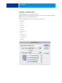
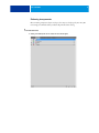
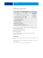
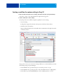
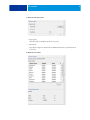
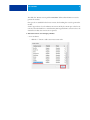
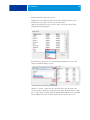
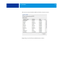
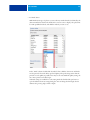
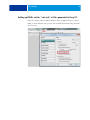
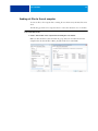
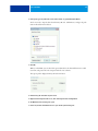
CUT CONTOURS
1
CUT CONTOURS
This document describes how to:
• Create a file with cut contours in the graphics application
• Set up a workflow for contour cutting in Fiery XF
• Set up ESKO i-cut for *.cut and *.ai files generated in Fiery XF
• Send cut files to the cut computer
For information on using print-and-cut devices, see the Fiery XF online user manual.
Creating a file with cut contours in the graphics application
Creating the cut contour
It is recommended that you save the path that describes a cut contour in a separate top layer
and that you select “Overprint stroke” in the Attributes menu for the spot color that is
assigned to the cut contour.
Adobe Illustrator® provides several methods for generating cut contours; use the tools you are
most comfortable with to draw contours around your image(s). If you are cutting around a
vector image, you should be able to use the vector contours themselves to create your outline.
You can also import cut contours created in another application, such as Adobe Photoshop®.
It is important that you align your cut contours to your print image when combining
print-and-cut information from multiple sources. Failure to do so will result in wrong
registrations during the cutting process.
Remember that the quality of your cut contours will directly affect your cutting results. Both
the efficacy and result quality of the cutting process depend directly on your cut contours, so
it is always a good idea to carefully inspect your work before sending it on to Fiery XF.
Good cut contours are smooth vector lines that wrap perfectly around both simple and
complex areas without any unnecessary details. Cut contours should always contain the
smallest amount of data necessary to produce the result you are trying to achieve.
Poor cut contours contain thousands of tiny movements that reduce the performance and
quality of the cutting process, and are often the result of raster-to-vector conversion. They
may also contain poor registration in critical areas, stray points, unnecessary paths, and paths
that overlap themselves. If you are using a bitmap-to-vector conversion tool to create your cut
contours, be sure to verify your results and perform the necessary clean-up before sending
your file to Fiery XF.
CUT CONTOURS
2
Assigning a named spot color
Fiery XF identifies cut contours using spot colors.
When the print file is imported into Fiery XF, the cut contours are extracted from the EPS or
PDF file to generate the cut path information.
Different default names for spot colors are supported in Fiery XF:
• Regmark
• Crease
• Kiss Cut
• Laser Cut
• Pen plot
• Router Cut
• Score
• Through Cut
• CutContour
• Die line
CUT CONTOURS
3
It is also possible to define custom spot colors to describe cut paths. You can add them to the
list of default names in Fiery XF. On the Finishing tab, open the Cut pane, and click the "+"
button.
Spot colors must be assigned to strokes. Remember to remove all fills assigned to those same
paths. To prevent any cut contour interpretation issues, all cut contour strokes should have a
minimum thickness of 0.01 points.
TO ASSIGN SPOT COLORS TO YOUR CUT CONTOURS
1 Select your cut contours and open the Swatches palette.
All cut contours should already have strokes applied.
2 Click New Swatch.
The Swatch Options dialog box opens.
3 Under “Swatch Name”, type the name of your spot color.
4 Change the color type to “Spot Color”.
5 Set the color mode to CMYK.
The associated values are not important.
6 Click OK to save your changes.
A new swatch appears in the palette.
It is a good idea to save all your Fiery XF supported contour spot colors in a single library that
can be recalled at any time. Doing so will reduce naming errors and inconsistencies.
CUT CONTOURS
Flattening transparencies
Files containing transparent objects and spot colors may not load properly into Fiery XF.
It is strongly recommended that you flatten all print files before saving.
TO FLATTEN PRINT FILES
1 Select your artwork, but do not select the cut contour layers.
4
CUT CONTOURS
5
2 On the Objects menu, click Flatten Transparency.
The Flatten Transparency dialog box opens.
3 Under “Preset”, make your preferred settings. Clear the “Convert All Strokes to Outlines”
check box to avoid double cut paths.
4 Select “Preserve Overprints and Spot Colors”.
5 Click Save Preset (optional).
It is recommended that you save your settings as a preset, e.g. Fiery_XF_Cutting.
6 Click OK to perform the action.
Saving the file
To save your file, on the File menu, click Save As, and choose either EPS or PDF for the file
format.
If you choose PDF, select the “Preserve Illustrator Editing Capabilities” check box in the Save
Adobe PDF dialog box.
If you choose EPS, on the Save As menu, select PostScript Level 3.
CUT CONTOURS
6
Creating a workflow for contour cutting in Fiery XF
1 Make sure that the Fiery XF server is running, launch the client and open System Manager.
To be able to do this, a user with administrative rights must be logged on.
2 Create a workflow for contour cutting.
Fiery XF provides some workflow templates especially for contour cutting.
• Contour Cutting
For all plotters supported by the Cut Server Option, and all i-cut-driven devices.
• Zund Cut Center Connectivity
Supports all Zund G3/S3 devices and enables direct communication through the network
to the ZCC software.
If you prefer to create your own contour cutting workflow, it is recommended that you make
the following settings in System Manager:
• On the Workflow tab, open the Preview pane, and set the preview to 72 dpi.
• On the Workflow tab, open the Speed pane, and set the RIP resolution to “High quality”.
• On the File tab, open the PS/EPS/PDF pane, and set in-RIP separation to “Force”.
CUT CONTOURS
7
3 On the Finishing tab, open the Cutting pane.
4 Select the cut device.
• Print between layout elements
This setting is required if i-cut is your device manufacturer and you want to output your
jobs as nestings or step & repeats. Selecting the check box ensures that additional marks
are placed between the elements of a nesting or a step & repeat job.
• Bleeding:
The default setting is 0.
This setting should be applied only to level1 cut contours that are based on the bounding
box. Applying a bleed value to level 2 cut contours that have been created in pre-press
could cause the cut contours to be cut off.
Entering a value changes the size of the bounding box that is used to generate the cut file.
The size of the bounding box increases if you select “Add frame”. It decreases if you select
“Cut image”.
It can be useful to enter a bleed value for “Cut image” to remove bleed that was defined in
the artwork.
CUT CONTOURS
5 Define the data export path.
• Export path:
Select the folder to which the cut files are exported.
• IP network
Fiery XF can output cut data directly to ZÜND G3/S3 devices via an IP network
connection.
6 Define the cut contour.
8
CUT CONTOURS
9
The check box “Extract contour path from EPS/PDF” defines what information is used to
generate the cut data.
If no spot color is available for level 2 cut contours, the bounding box is used to generate the
cut data.
A scissor sign in front of a color indicates cut contours. If the job contains spot colors for cut
contours, select the check box to ensure that Fiery XF recognizes them as contour colors to be
extracted as cut data. Cut contours are not printed.
7 Add custom contour colors and apply a method.
• For i-cut devices
– Click the "+" button to add a custom cut contour color.
CUT CONTOURS
10
– Define a method for each contour source.
Defining the correct method for each contour source enables Fiery XF to create
different layers of cut data to send to the i-cut-driven device.
Click on the method for a contour source to edit it. A drop-down list box with
predefined methods is displayed.
If the method you want to use is not listed, click User defined to create one. The
Custom cut methods dialog box opens.
Click the “+” button to add a new row to the table. Then, enter the name of the
custom contour cut method by overwriting “Enter custom cut method name”. Click
the “+” button again to confirm, and then click OK. (If the OK button is not available,
select a different cut contour in the list and then reselect the new cut contour.)
CUT CONTOURS
The new cut contour method is added to the list of contour sources.
Repeat the process for all your standard contour sources.
11
CUT CONTOURS
12
• For Zünd devices
With Zünd G3/S3 types of plotters, you can select any standard method, as defined by the
device manufacturer. Click on the method for a contour source to display a drop-down list
box with predefined methods, and click the method you want to use.
In the “Mode” column, double-click “Standard”. Then, click the down arrow and click a
mode (optional). The mode affects speed and quality. The speed setting ensures that the
printout is cut as quickly as possible, but it may not be exact. With the quality setting, the
cut is more precise, but it takes longer.
Advanced settings are available for some cutting methods. Click the blue pen button to
open the Advanced contour settings dialog box. You can change the line length, the bit
diameter, the grooving angle, and the z depth.
CUT CONTOURS
13
Setting up ESKO i-cut for *.cut and *.ai files generated in Fiery XF
In the i-cut software, make sure that the check box “Move to (0.0) after Import” is cleared.
Failing to do this will result in the position of the cut marks/camera marks being offset with
the cut contours.
CUT CONTOURS
14
Sending cut files to the cut computer
To write cut files to the computer that is running the cut software, Fiery XF must have write
access.
The following procedure is for computers that are on the same subnet but not on a domain.
TO ALLOCATE WRITE ACCESS
1 Create a shared folder on the computer that is running the i-cut software.
Make sure that the folder is shared and that the group “Everyone” has full control. In the
example below, the shared folder is Win7_XF_5.0 and the user is named EFI.
CUT CONTOURS
15
2 In Fiery XF, type the path name of the shared folder as \\IP_Address\ShareName.
You do not need to map the drive from the Fiery XF side. Click Browse, and type the path
name in the Folder name edit box.
3 Click OK.
When you click OK, you are asked for login credentials for the shared folder. Enter a valid
user name and password for the computer with the i-cut software.
The export path is displayed in Fiery XF as shown below:
4 Exit the Fiery XF client and stop the server.
5 Right-click the Fiery XF Control icon, and click Fiery XF Server Configuration.
6 The Windows Services dialog box opens.
7 In the list, double-click EFI XF Server to open the Properties dialog box.
CUT CONTOURS
8 On the Log On tab, set the Fiery XF server service to log in with the same user name and
password as an authorized user on the computer that is running the i-cut software.
9 Click OK.
10 Restart the Fiery XF server and the Fiery XF client.
16