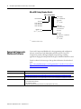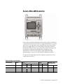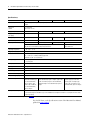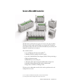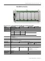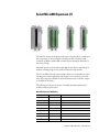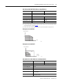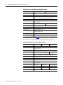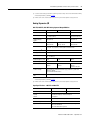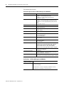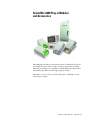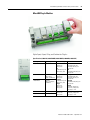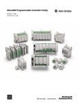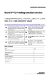
1
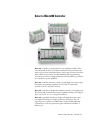
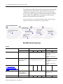
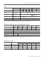
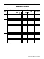
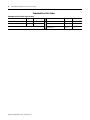
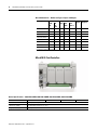
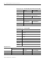
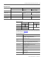
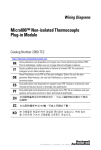
Micro800 Programmable Controller Family
Bulletin 2080
Selection Guide
Important User Information
Solid state equipment has operational characteristics differing from those of electromechanical equipment. Safety Guidelines for the Application,
Installation and Maintenance of Solid State Controls (publication SGI-1.1 available from your local Rockwell Automation sales office or online at
http://rockwellautomation.com/literature) describes some important differences between solid state equipment and hard-wired electromechanical
devices. Because of this difference, and also because of the wide variety of uses for solid state equipment, all persons responsible for applying this
equipment must satisfy themselves that each intended application of this equipment is acceptable.
In no event will Rockwell Automation, Inc. be responsible or liable for indirect or consequential damages resulting from the use or application of this
equipment.
The examples and diagrams in this manual are included solely for illustrative purposes. Because of the many variables and requirements associated
with any particular installation, Rockwell Automation, Inc. cannot assume responsibility or liability for actual use based on the examples and
diagrams.
No patent liability is assumed by Rockwell Automation, Inc. with respect to use of information, circuits, equipment, or software described in this
manual.
Reproduction of the contents of this manual, in whole or in part, without written permission of Rockwell Automation, Inc., is prohibited.
Throughout this manual, when necessary, we use notes to make you aware of safety considerations.
WARNING
Identifies information about practices or circumstances that can cause an explosion in a hazardous environment, which may
lead to personal injury or death, property damage, or economic loss.
IMPORTANT
Identifies information that is critical for successful application and understanding of the product.
ATTENTION
Identifies information about practices or circumstances that can lead to: personal injury or death, property damage, or
economic loss. Attentions help you identify a hazard, avoid a hazard, and recognize the consequence.
SHOCK HAZARD
Labels may be on or inside the equipment, such as a drive or motor, to alert people that dangerous voltage may be present.
BURN HAZARD
Labels may be on or inside the equipment, such as a drive or motor, to alert people that surfaces may reach dangerous
temperatures.
Allen-Bradley, Rockwell Automation, Micro800, Micro810, Micro830, Micro850, Connected Components Workbench, and TechConnect are trademarks of Rockwell Automation, Inc.
Trademarks not belonging to Rockwell Automation are property of their respective companies.
Select a Micro800 Controller
Micro800™ controllers are designed for low-cost, standalone machines. These
economical small-size PLCs are available in different form factors based on the
number of I/O points embedded in the base, with a range of features intended to
address different requirements. The Micro800 family shares programming
environment, accessories and plug-ins that allow machine builders to personalize
the controller for specific capabilities.
Micro810™ controllers function as a smart relay with high current relay outputs,
but with the programming capabilities of a micro PLC. The Micro810
controllers come in a 12-point form factor.
Micro830™ controllers are designed for standalone machine control applications.
They have flexible communications and I/O capabilities with up to five plug-ins.
They come as a 10-, 16-, 24-, or 48-point form factors.
Micro850™ expandable controllers are designed for applications that require
more digital and analog I/O or higher performance analog I/O. They can
support up to four expansion I/O. Micro850 controllers include additional
communication connection options through an embedded 10/100 Base-T
Ethernet port.
1
Publication 2080-SG001C-EN-P - September 2012
2
Micro800 Programmable Controller Family Selection Guide
Several Micro830 and Micro850 controllers support basic positioning through
embedded pulse train outputs (PTO). These controllers also allow you to
configure up to six high speed counters (HSC), and choose from nine HSC
operation modes. (HSC is supported on all Micro830 and Micro850 catalogs,
except on 2080-LCxx-xxAWB. PTO is only supported on Micro830 and
Micro850 catalog numbers that end in BB or VB.)
This selection guide serves to help you identify the right controller, plug-ins,
expansion I/O, and accessories, based on your requirements.
Choose a Micro800 Controller
2
1
Select a Micro810
controller (go to page 7)
Select a Micro800 controller
(go to page 2)
3
4
Select Micro800
Plug-Ins and
Accessories
(go to page 43)
Select a Micro830
controller (go to page 9)
Select Micro850
Expansion I/O
(go to page 25)
Select a Micro850
controller
(go to page 15)
Micro800 Controllers Comparison
Features
Attribute
Communication ports, embedded
Micro810
Micro830
Micro850
12-point
10-point
USB 2.0 (with USB adapter)
USB 2.0 (non-isolated)
RS232/RS485 non-isolated combo serial
16-point
24-point
48-point
24-point
48-point
USB 2.0 (non-isolated)
RS232/RS485 non-isolated
combo serial
10/100 Base T Ethernet port
(RJ-45)
Base programming port
USB 2.0 (with USB adapter).
Any standard USB printer
cable will work.
Embedded USB 2.0 (non-isolated)
Any standard USB printer cable will work
Embedded USB 2.0
(non-isolated)
Any standard USB printer cable
will work
10/100 Base T Ethernet port
(RJ-45)
Base digital I/O points
(see Number and Types of
Inputs/Outputs for Micro810,
Micro830, and Micro850 Catalogs
on page 5)
12
10
Base analog I/O channels
Four 24V DC digital inputs
can be configured as
0…10V analog inputs (DC
input models only)
via Plug-In Modules
Base number of plug-in modules
0
2
Publication 2080-SG001C-EN-P - September 2012
16
2
24
48
24
48
via Plug-in modules
and Expansion I/O
3
5
3
5
Micro800 Programmable Controller Family Selection Guide
3
Features
Attribute
Maximum digital I/O(1)
Types of accessories or plug-ins
supported
Micro810
Micro830
12-point
10-point
16-point
24-point
48-point
24-point
12
26
32
48
88
132
• LCD display with backup
memory module
• USB adapter
Micro850
48-point
All plug-in modules (see page 43)
Types of Expansion I/O supported
—
—
All expansion I/O modules
(see page 25)
Power supply
Embedded 120/240V AC and
12/24V DC options
Base unit has embedded 24V DC power supply, optional external 120/240V AC
power supply available
Basic instruction speed
2.5 μs per basic instruction
0.30 μs per basic instruction
Software
Connected Components Workbench
(1) For Micro830 controllers, the number of maximum digital I/O assumes 8-point digital I/O plug-ins (for example, 2080-IQ4OB4) are used on all available plug-in slots. For
Micro850 controllers, the maximum number of digital I/O supported between the base, plug-ins, and expansion I/O is 132.
Micro800 Controller Programming Comparison (with Connected Components Workbench)
Attribute
Micro810
12-point
Micro830
10/16-point
Micro830
24-point
Micro830
48-point
Micro850
24-point
Micro850
48-point
Program steps(1)
2K
4K
10 K
10 K
10 K
10 K
Data bytes
2 KB
8 KB
20 KB
20 KB
20 KB
20 KB
IEC 61131-3 languages
Ladder diagram, function block diagram, structured text
User defined function blocks
Yes
Floating point
32-bit & 64-bit
PID Loop Control
Yes
Yes
Embedded serial port protocols
None
Modbus Master/Slave, ASCII/Binary, CIP Serial Server
(1) Estimated Program and Data size are “typical” – program steps and variables are created dynamically. 1 Program Step = 12 data bytes. The number of bytes per instruction
can vary greatly from program to program and from programming language to programming language.
Micro800 Communication Options
Controller
USB progamming port
Embedded Serial Port, Serial Port Plug-In
CIP Serial
Modbus RTU
Modbus/TCP
EtherNet/IP
ASCII/Binary
Micro810
Yes (with adapter)
No
Micro830
Yes
Server (1)
(Release 2)
Master/Slave
No
No
Yes
Micro850
Yes
Server(1)
Master/Slave
Server(1)
Server(1)
Yes
(1) Client will be available at later release.
Publication 2080-SG001C-EN-P - September 2012
4
Micro800 Programmable Controller Family Selection Guide
Micro800 Power Requirements(1)
Controller/Module
Power Requirement
Micro810 12-point
(with or without LCD)
3 W (5V A for AC module)
Micro830 and Micro850
(without plug-in/expansion I/O)
10/16-point
24-point
48-point
5W
8W
11 W
Plug-in modules, each
1.44 W
Expansion I/O
(system bus power consumption)
2085-IQ16
2085-IQ32T
2085-IA8
2085-IM8
2085-OA8
2085-OB16
2085-OV16
2085-OW8
2085-OW16
2085-IF4
2085-IF8
2085-OF4
2085-IRT4
–
–
–
–
–
–
–
–
–
–
–
–
–
0.85 W
0.95 W
0.75 W
0.75 W
0.90 W
1.00 W
1.00 W
1.80 W
3.20 W
1.70 W
1.75 W
3.70 W
2.00 W
(1) When setting up a Micro800 system, verify that total power consumption of the controller,
plug-in and expansion I/O does not exceed the output power capacity of the power supply used.
See External Power Supply (2080-PS120-240VAC) on page 50 for power supply specifications.
Micro800 Controller Analog I/O comparison
Publication 2080-SG001C-EN-P - September 2012
Analog Accuracy Level Required
Component Recommended
Low
Micro810 – 4-channel embedded analog
- 10-bit non-isolated 0…10V inputs
- 2% accuracy with user calibration
- limited filtering
- each channel shared with digital input
Medium
Micro830 (with plug-ins)
- 12-bit non-isolated 0…10V, 0…20 mA
- 1% Accuracy, inputs and outputs
- 14-bit non-isolated RTD/TC (1 °C accuracy)
- 200 ms/ch, 50/60 Hz filtering
High
Micro850 (with expansion I/O)
- input: 14 bit, isolated, 0…10V, 4…20 mA
- 8 ms update rate with or without 50/60 Hz rejection
- output: 12 bit, isolated, -10…10V, 0…20 mA
- ±0.5…±3.0 °C accuracy for Thermocouple inputs
- ±0.2…±0.6 °C accuracy for RTD inputs
Micro800 Programmable Controller Family Selection Guide
5
Number and Types of Inputs/Outputs
Number and Types of Inputs/Outputs for Micro810, Micro830, and Micro850 Catalogs
Controller
Family
Catalogs
Micro810
2080-LC10-12QWB
Inputs
120V AC
Outputs
120 /
240V AC
24V
DC/
V AC
8
2080-LC10-12AWA
8
Micro850
6
2080-LC30-10QVB
6
10
10
2080-LC30-16QVB
10
2080-LC30-24QWB
14
2080-LC30-24QVB
14
2080-LC30-24QBB
14
28
4
4
4
4
2
4
1
2
6
2
6
1
10
2
4
10
10
2
4
2
4
20
2080-LC30-48QWB
28
2080-LC30-48QVB
28
2080-LC30-48QBB
28
14
20
6
20
3
6
20
3
6
10
2
4
2
4
10
2080-LC50-24QBB
14
2080-LC50-24QVB
14
2080-LC50-24QWB
14
2080-LC50-48AWB
4
6
2080-LC30-16QWB
2080-LC50-24AWB
24V DC
Sink
4
8
2080-LC30-10QWB
2080-LC30-48AWB
24V DC
Source
PTO
HSC
Support Support(1)
4
2080-LC10-12DWD
2080-LC30-16AWB
Relay
4
8
2080-LC10-12QBB
Micro830
12V
DC
Analog In
0…10V
(shared with
DC In)
28
10
10
4
20
2080-LC50-48QWB
28
2080-LC50-48QBB
28
2080-LC50-48QVB
28
20
6
20
20
3
6
3
6
(1) Maximum number of HSC supported.
Publication 2080-SG001C-EN-P - September 2012
6
Micro800 Programmable Controller Family Selection Guide
Micro800 Catalog Number Details
2080 - LC 30- 24 Q V B
Bulletin Number
Base Unit
LC10 = Micro810
LC30 = Micro830
LC50 = Micro850
Number of I/O
10, 12(1), 16, 24, 48
Power Supply
A(1) = 120/240V AC
B = 24V DC
D(1) = 12V DC
Output Type
B = 24V DC Source
V = 24V DC Sink
W = Relay
Input Type
A = 110V AC or 110/220V AC
Q = 24V AC/DC
D(1) = 12V DC
(1)
Connected Components
Workbench Software
Available for Micro810 only.
Connected Components Workbench™ is the programming and configuration
software environment for the Micro800 controllers and our Connected
Components products offering. It simplifies setup and usage, enabling
applications ranging from simple Smart Relay up to Standalone Machine control.
Visit the website for the most up-to-date product information, downloads and
tools:
http://ab.rockwellautomation.com/Programmable-Controllers/Connected-Co
mponents-Workbench-Software.
Attribute
Basic
Delivery
Download for FREE from the Connected Components Workbench web page at
http://ab.rockwellautomation.com/Programmable-Controllers/Connected-Components-Workbench-Software.
Packaging options
Available on DVD, orderable from Connected Components Workbench web page at
http://ab.rockwellautomation.com/Programmable-Controllers/Connected-Components-Workbench-Software.
Features
• LD, FBD and ST editors
• user-defined function blocks
• No activation needed
• Optional registration during installation (for product updates and notices)
Publication 2080-SG001C-EN-P - September 2012
Select a Micro810 Controller
As the smallest of the Micro800 family, the Micro810 controller is available in a
12-point version, with two 8 A and two 4 A outputs that eliminate the need for
external relays. The Micro810 features embedded smart relay function blocks
that can be configured from a 1.5” LCD and keypad. The function blocks
include Delay OFF/ON Timer, Time of Day, Time of Week and Time of Year
for applications requiring a programmable timer and lighting control.
Programming can also be done through a program download via USB
programming port, using Connected Components Workbench Software.
To help you select a Micro810 controller, consult the specifications for each
catalog in the next section.
Number and Types of Inputs/Outputs
Catalog Number
Power
Inputs
120V AC
7
Outputs
240V AC
12…24V DC /V AC Relay
2080-LC10-12QWB
24V DC
8
2080-LC10-12AWA
120…240V AC
2080-LC10-12QBB
12…24V DC
8
2080-LC10-12DWD
12V DC
8
8
24 V DC SRC
4
Analog In 0…10V
(shared with DC In)
4
4
4
4
4
4
Publication 2080-SG001C-EN-P - September 2012
8
Micro800 Programmable Controller Family Selection Guide
Specifications(1)
Attribute
2080-LC10-12AWA
2080-LC10-12QWB
Number of I/O
8 Input (4 digital, 4 analog/digital, configurable)
4 Output
Dimensions
HxWxD
91 x 75 x 59 mm
(3.58 x 2.95 x 2.32 in.)
Supply voltage range
85…263V DC
20.4…26.4V DC
Supply frequency range
(AC supply)
47…63 Hz
–
Voltage range
100…240V AC, 50/60 Hz
24V DC Class 2
Power consumption
5V A
3W
I/O rating
Input: 120…240V AC
Input: 24V DC, 8 mA
2080-LC10-12DWD
2080-LC10-12QBB
10.8V…13.2V DC
11.4V..26.4V DC
12V DC Class 2
12/24V DC Class 2
Input: 12V DC, 8 mA
Input: 24V DC, 8 mA
Output: Relay 00 & 01: 8 A @ 240V AC, B300, R300, General Use
Relay 02 & 03: 4 A @ 240V AC, C300, R150, General Use
Output: 24V DC 1A, 25 °C,
24V DC 0.5A 55 °C
Operating temperature
0…55 °C (32…131 °F)
Shipping weight, approx.
0.203 kg (0.448 lb)
Wire size
0.32...2.1 mm² (22...14 AWG) solid copper wire or
0.32...1.3 mm² (22...16 AWG) stranded copper wire
rated @ 90 °C (194 °F ) insulation max.
Wiring category
2 – on signal ports
2 – on power ports
Wiring torque
1.085 Nm (8 lb-in.)
Wire type
use Copper Conductors only
Fuse, type
Rated 250V 3.15 A-RADIAL
Enclosure type rating
Meets IP20
North American temp code
T5
Insulation stripping length
7 mm (0.28 in.)
Isolation voltage
250V (continuous),
Reinforced Insulation Type,
I/O to Aux and Network,
Inputs to Outputs. Type
tested for 60 s 3250V DC,
I/O to Aux and Network,
Inputs to Outputs
AC input filter setting
16 ms for all embedded inputs
(In Connected Components Workbench, go to the Embedded I/O configuration window to re-configure the filter setting
for each input group)
250V (continuous), Reinforced Insulation Type, I/O
to Aux and Network, Inputs to Outputs Type tested
for 60 s @ 720V DC, Inputs to Aux and Network,
3250V DC Outputs to Aux and Network, Inputs to
Outputs
50V (continuous), Reinforced
Insulation Type, I/O to Aux and
Network, Inputs to Outputs Type
tested for 60 s @ 720V DC, I/O to
Aux and Network, Inputs to Outputs
(1) See the Micro810 User Manual, publication 2080-UM001, for more Micro810 controller specifications.
For relay life chart, see the Specifications section of the Micro810 User Manual,
publication 2080-UM001.
Publication 2080-SG001C-EN-P - September 2012
Select a Micro830 Controller
The Micro830 controller allows integration of as many as five plug-in modules.
The plug-in modules enable machine builders to personalize the controllers to
increase functionality. It also offers removable terminal blocks (most models) and
simplified communication via serial port.
The controllers include:
• up to six High-Speed Counter inputs (HSC)(1)
• 100 kHz speed HSC available on 24V DC models
•
•
•
•
•
•
up to three embedded Pulse Train Outputs (PTO) for basic positioning(2)
High speed input interrupts
Modbus RTU protocol (serial port)
CIP Serial to allow tighter integration with PanelView Component
Embedded USB programming and serial port (RS232/485)
Plug-in slots to customize according to needs
To help you select a Micro830 controller, check out the specifications for each
catalog in the next section.
(1) HSC is supported on all Micro830 catalog numbers, except on 2080-LC30-xxAWB.
(2) PTO is supported on Micro830 catalog numbers ending in BB or VB only.
9Publication 2080-SG001C-EN-P - September 2012
10
Micro800 Programmable Controller Selection Guide
Inputs and Outputs
Micro830 Controllers – Number and Type of Inputs/Outputs
Catalog Number
Inputs
120V AC
Outputs
24V DC/V AC Relay
2080-LC30-10QWB
6
2080-LC30-10QVB
6
2080-LC30-16AWB
10
24V Source
4
HSC
Support(1)
2
4
1
2
6
2080-LC30-16QWB
10
2080-LC30-16QVB
10
2080-LC30-24QBB
14
2080-LC30-24QVB
14
2080-LC30-24QWB
14
2080-LC30-48AWB
24V Sink
PTO
Support
28
6
2
6
10
10
1
2
2
4
2
4
10
4
20
2080-LC30-48QBB
28
2080-LC30-48QVB
28
2080-LC30-48QWB
28
20
20
3
6
3
6
20
6
(1) Maximum number of HSC supported.
Micro830 Controllers General Features
Attribute
10-point
2080-LC30-10QWB
2080-LC30-10QVB
16-point
2080-LC30-16AWB
2080-LC30-16QWB
2080-LC30-16QVB
24-point
2080-LC30-24QWB
2080-LC30-24QVB
2080-LC30-24QBB
48-point
2080-LC30-48AWB
2080-LC30-48QWB
2080-LC30-48QVB
2080-LC30-48QBB
Number of I/O
10 (6 inputs, 4 outputs)
16 (10 inputs, 6 outputs)
24 (14 inputs, 10 outputs)
48 (28 inputs, 20 outputs)
Dimensions, HxWxD
90 x 100 x 80 mm
(3.54 x 3.94 x 3.15 in.)
90 x 100 x 80 mm
(3.54 x 3.94 x 3.15 in.)
90 x 150 x 80 mm
(3.54 x 5.91 x 3.15 in.)
90 x 230 x 80 mm
(3.54 x 9.06 x 3.15 in.)
Shipping weight, approx.
0.302 kg (0.666 lb)
0.302 kg (0.666 lb)
0.423 kg (0.933 lb)
0.725 kg (1.60 lb)
Operating temperature
-20…65 °C (-4…149 °F)
Wire size
0.14…2.5 mm2 (26…14 AWG) solid copper wire or
0.14…1.5 mm2 (26…16 AWG) stranded copper wire
rated @ 90 °C (194 °F ) insulation max
Wiring category(1)
2 – on signal ports; 2 – on power ports
Wire type
Use copper conductors only
Terminal screw torque
0.6 Nm (4.4 lb-in.) max
(using a 2.5 mm (0.10 in.) flat-blade screwdriver)
Power consumption
7.88 W
Power supply voltage range
20.4…26.4V DC Class 2
Insulation stripping length
7 mm (0.28 in.)
Enclosure type rating
Meets IP20
North American temp code
T4
(1)
0.2…2.5 mm2 (24…14 AWG) solid copper wire or
0.2…2.5 mm2 (24…14 AWG) stranded copper wire
rated @ 90 °C (194 °F ) insulation max
12.32 W
18.2 W
Use this Conductor Category information for planning conductor routing. Refer to Industrial Automation Wiring and Grounding Guidelines, publication 1770-4.1.
Publication 2080-SG001C-EN-P - September 2012
Micro800 Programmable Controller Selection Guide
11
Micro830 Controllers 10- and 16-Point Controllers
General Specifications – 10-point controllers
Attribute
2080-LC30-10QWB
Input circuit type
12/24V sink/source (standard)
24V sink/source (high-speed)
Output circuit type
Relay
2080-LC30-10QVB
24V DC sink transistor standard and high-speed
Event input interrupt support Yes
I/O rating
Input 24V DC, 8.8 mA
Output 2 A, 240V AC, general use
Input 24V DC, 8.8 mA
Output 2 A, 24V DC, 1 A per point
(Surrounding air temperature 30 °C)
24V DC, 0.3 A per point (Surrounding air temperature
65 °C)
Isolation voltage
250V (continuous), Reinforced Insulation Type, Outputs to
Aux and Network, Inputs to Outputs
Type tested for 60 s @ 720V DC, Inputs to Aux and Network,
3250V DC Outputs to Aux and Network, Inputs to Outputs
50V (continuous), Reinforced Insulation Type, I/O to Aux
and Network, Inputs to Outputs
Type tested for 60 s @ 720V DC, I/O to Aux and Network,
Inputs to Outputs
Pilot duty rating
C300, R150
—
General Specifications – 16-point controllers
Attribute
2080-LC30-16AWB
2080-LC30-16QWB
Input circuit type
120V AC
12/24V sink/source (standard)
24V sink/source (high-speed)
Output circuit type
Relay
Event input interrupt
support
Yes
2080-LC30-16QVB
12/24V DC sink transistor standard
and high-speed
Publication 2080-SG001C-EN-P - September 2012
12
Micro800 Programmable Controller Selection Guide
General Specifications – 16-point controllers
Attribute
2080-LC30-16AWB
2080-LC30-16QWB
2080-LC30-16QVB
I/O rating
Input 120V AC, 16 mA
Output 2 A, 240V AC, general use
Input 24V DC, 8.8 mA
Output 2 A, 240V AC, general use
Input 24V DC, 8.8 mA
Output 24V DC, 1 A per point
(Surrounding air temperature 30 °C)
24 V DC, 0.3 A per point (Surrounding
air temperature 65 °C)
Isolation voltage
250V (continuous), Reinforced Insulation Type, Outputs to Aux and Network,
Inputs to Outputs
2080-LC30-16AWB: Type tested for 60 s @ 3250V DC I/O to Aux and Network,
Inputs to Outputs
2080-LC30-16QWB: Type tested for 60 s @ 720V DC, Inputs to Aux and
Network, 3250V DC Outputs to Aux and Network, Inputs to Outputs
Pilot duty rating
C300, R150
50V (continuous), Reinforced
Insulation Type, I/O to Aux and
Network, Inputs to Outputs
Type tested for 60s @ 720V DC, I/O to
Aux and Network, Inputs to Outputs
—
Micro830 24-Point Controllers
General Specifications – 24-point controllers
Attribute
2080-LC30-24QWB
Input circuit type
24V DC sink/source standard and high-speed
Output circuit type
Relay
Event input interrupt
support
Yes
I/O rating
Input 24V DC, 8.8 mA
Output 2 A, 240 V AC, general use
Input 24V DC, 8.8 mA
Output 24V DC, Class 2, 1 A per point (Surrounding air temperature 30 °C)
24V DC, Class 2, 0.3 A per point (Surrounding air temperature 65 °C)
Isolation voltage
250V (continuous), Reinforced Insulation Type,
Outputs to Aux and Network, Inputs to Outputs
Type tested for 60 s @ 720V DC, Inputs to Aux
and Network, 3250V DC Outputs to Aux and
Network, Inputs to Outputs
50V (continuous), Reinforced Insulation Type, I/O to Aux and Network,
Inputs to Outputs
Type tested for 60 s @ 720V DC, I/O to Aux and Network, Inputs to Outputs
Publication 2080-SG001C-EN-P - September 2012
2080-LC30-24QVB
2080-LC30-24QBB
24V DC sink standard and
high-speed
24V DC source standard and
high-speed
Micro800 Programmable Controller Selection Guide
13
General Specifications – 24-point controllers
Attribute
2080-LC30-24QWB
2080-LC30-24QVB
Pilot duty rating
C300, R150 (2080-LC30-24QWB only)
—
2080-LC30-24QBB
Micro830 48-Point Controllers
General Specifications – 48-point controllers
Attribute
2080-LC30-48AWB
2080-LC30-48QWB
2080-LC30-48QVB
Input circuit type
120V AC
24V DC sink/source standard and high-speed
Output circuit type
Relay
Event input interrupt
support
Yes, inputs 0…15 only
I/O rating
Input 120V AC, 16 mA
Output 2 A, 240V AC,
general use
Pilot duty rating
C300, R150
Isolation voltage
250V (continuous),
Reinforced Insulation Type,
Outputs to Aux and Network,
Inputs to Outputs
Type tested for 60 s @
3250V DC I/O to Aux and
Network, Inputs to Outputs
24V DC sink standard and
high-speed
Input 24V DC, 8.8 mA
Output 2 A, 240V AC,
general use
2080-LC30-48QBB
24V DC source standard and
high-speed
Input 24V DC, 8.8 mA
Output 24V DC, 1 A per point (Surrounding air temperature 30 °C)
24 V DC, 0.3 A per point (Surrounding air temperature 65 °C)
–
250V (continuous),
Reinforced Insulation Type,
Outputs to Aux and
Network, Inputs to Outputs
Type tested for 60 s @
720V DC, Inputs to Aux and
Network, 3250V DC
Outputs to Aux and
Network, Inputs to Outputs
50V (continuous), Reinforced Insulation Type, I/O to Aux and
Network, Inputs to Outputs
Type tested for 60 s @ 720V DC, I/O to Aux and Network,
Inputs to Outputs
For relay life chart, see the Specifications section of the Micro830 and Micro850
User Manual, publication 2080-UM002.
Publication 2080-SG001C-EN-P - September 2012
14
Micro800 Programmable Controller Selection Guide
Embedded Serial Port Cables
Embedded Serial Port Cable Selection Chart
Connectors
Length
8-pin Mini DIN to 8-pin Mini DIN
8-pin Mini DIN to 8-pin Mini DIN
Connectors
Length
0.5 m (1.5 ft) 1761-CBL-AM00(1)
8-pin Mini DIN to 9-pin D Shell
0.5 m (1.5 ft) 1761-CBL-AP00(1)
2 m (6.5 ft)
8-pin Mini DIN to 9-pin D Shell
2 m (6.5 ft)
1761-CBL-PM02(1)
8-pin Mini DIN to 6-pin RS-485
terminal block
30 cm
(11.8 in.)
1763-NC01 series A
(1) Series C or later for Class 1 Div 2 applications.
Publication 2080-SG001C-EN-P - September 2012
Cat. No.
1761-CBL-HM02(1)
Cat. No.
Select a Micro850 Controller
A Micro850 controller with a power supply, plug-in
modules, and four expansion I/O modules attached
Micro850 controllers are suitable for applications that require more digital and
analog I/O or higher performance analog I/O. These controllers can support up
to four expansion I/O. It comes in a 24-point and 48-point form factor with an
embedded Ethernet port.
Micro850 controllers include:
• Expansion I/O support
• up to six High-Speed Counter inputs (HSC)(1)
• 100 kHz speed HSC available on 24V DC models
•
•
•
•
•
•
•
•
•
up to three embedded Pulse Train Outputs (PTO)(2) for basic positioning
High speed input interrupts
Modbus RTU protocol (serial port)
Modbus/TCP Server support
EtherNet/IP Server support
CIP Serial (Server)
Embedded USB programming and serial port (RS232/485)
Embedded 10/100 Base-T Ethernet port (RJ45)
Plug-in slots to customize according to needs
To help you select a Micro850 controller, see the following specifications.
(1) HSC is supported on all Micro850 catalog numbers, except on 2080-LC50-xxAWB.
(2) PTO is supported on Micro850 catalog numbers ending in BB or VB.
15
Publication 2080-SG001C-EN-P - September 2012
16
Micro800 Programmable Controller Family Selection Guide
Micro850 Controllers – Number and Types of Inputs and Outputs
Catalog Number
Inputs
120V
AC
2080-LC50-24AWB
Outputs
24V
DC/
V AC
14
24V
Sink
24V
Source
HSC
Support(1)
2
4
2
4
10
2080-LC50-24QBB
14
2080-LC50-24QVB
14
2080-LC50-24QWB
14
2080-LC50-48AWB
Relay
PTO
Support
28
10
10
10
4
20
2080-LC50-48QBB
28
2080-LC50-48QVB
28
2080-LC50-48QWB
28
20
20
20
3
6
3
6
6
(1) Maximum number of HSC supported.
Micro850 24-Point Controllers
General Specifications – 2080-LC50-24AWB, 2080-LC50-24QWB, 2080-LC50-24QVB, 2080-LC50-24QBB
Attribute
2080-LC50-24AWB
Number of I/O
24 (14 inputs, 10 outputs)
Dimensions, HxWxD
90 x 158 x 80 mm (3.54 x 6.22 x 3.15 in.)
Shipping weight, approx.
0.423 kg (0.933 lb)
Publication 2080-SG001C-EN-P - September 2012
2080-LC50-24QWB
2080-LC50-24QVB
2080-LC50-24QBB
Micro800 Programmable Controller Family Selection Guide
17
General Specifications – 2080-LC50-24AWB, 2080-LC50-24QWB, 2080-LC50-24QVB, 2080-LC50-24QBB
Attribute
2080-LC50-24AWB
2080-LC50-24QWB
2080-LC50-24QVB
2080-LC50-24QBB
Wire size
Min
Max
Solid
2 (24 AWG)
0.2 mm
2.5 mm2 (14 AWG)
Stranded
0.2 mm2 (24 AWG)
2.5 mm2 (14 AWG)
rated @ 90 °C (194 °F ) insulation max
Wiring category(1)
2 – on signal ports
2 – on power ports
2 – on communication ports
Wire type
Use copper conductors only
Terminal screw torque
0.6 Nm (4.4 lb-in.) max
(using a 2.5 mm (0.10 in.) flat-blade screwdriver)
Input circuit type
120V AC
Output circuit type
Relay
Power consumption
28 W
Power supply voltage range
20.4…26.4V DC Class 2
I/O rating
Input 120V AC 16 mA
Output 2 A, 240 V AC, 24V DC
Input 24V, 8.8 mA
Output 2 A, 240 V AC,
24V DC
Input 24V, 8.8 mA
Output 24V DC, Class 2, 1 A per point (surrounding
air temperature 30 °C)
24 V DC, Class 2, 0.3 A per point (surrounding air
temperature 65 °C)
Isolation voltage
250V (continuous), Reinforced
Insulation Type, Output to Aux and
Network, Inputs to Outputs.
Type tested for 60 s @ 3250V DC
Output to Aux and Network,
Inputs to Outputs
250V (continuous),
Reinforced Insulation Type,
I/O to Aux and Network,
Inputs to Outputs.
Type tested for 60 s @
3250V DC Output to Aux
and Network, Inputs to
Outputs.
50V (continuous), Reinforced Insulation Type, I/O to
Aux and Network, Inputs to Outputs.
Type tested for 60 s @ 720V DC, I/O to Aux and
Network, Inputs to Outputs.
150V (continuous), Reinforced
Insulation Type, Input to Aux and
Network.
Type tested for 60 s @ 1950V DC
Input to Aux and Network
Pilot duty rating
C300, R150
Insulation stripping length
7 mm (0.28 in.)
Enclosure type rating
Meets IP20
North American temp code
T4
24V DC sink/source standard and high-speed
24V DC sink standard
and high-speed
24V DC source standard
and high-speed
50V (continuous),
Reinforced Insulation Type,
Input to Aux and Network
Type tested for 60 s @
720V DC, Inputs to Aux
and Network.
—
(1) Use this Conductor Category information for planning conductor routing. Refer to Industrial Automation Wiring and Grounding Guidelines,
publication 1770-4.1.
Publication 2080-SG001C-EN-P - September 2012
18
Micro800 Programmable Controller Family Selection Guide
DC Input Specifications –2080-LC50-24QBB, 2080-LC50-24QVB, 2080-LC50-24QWB
Attribute
High-Speed DC Input
(Inputs 0…7)
Standard DC Input
(Inputs 8 and higher)
Number of Inputs
8
6
Voltage category
24V sink/source
Input group to backplane
isolation
Verified by one of the following dielectric tests: 720V DC for 2 s
50V DC working voltage (IEC Class 2 reinforced insulation)
On-state voltage range
16.8…26.4V DC @ 65 °C (149 °F)
16.8…30.0V DC @ 30 °C (86 °F)
Off-state voltage
5V DC, max
Off-state current
1.5 mA, max
On-state current
5.0 mA @ 16.8V DC, min
7.6 mA @ 24V DC, nom
12.0 mA @ 30V DC, max
1.8 mA @ 10V DC, min
6.15 mA @ 24V DC, nom
12.0 mA @ 30V DC, max
Nominal impedance
3 kΩ
3.74 kΩ
IEC input compatibility
Type 3
10…26.4V DC @ 65 °C (149°F)
10…30.0V DC @ 30 °C (86°F)
AC Input Specifications – 2080-LC50-24AWB
Attribute
Value
Number of inputs
14
On-state voltage
79V AC, min
132V AC, max
On-state current
5 mA, min
16 mA, max
Input frequency
50/60 Hz, nom
47 Hz, min
63 Hz, max
Off-state voltage
20V AC @ 120V AC, max
Off-state current
2.5 mA @ 120V AC, max
Inrush current
250 mA @ 120V AC, max
Inrush delay time
constant max
22 ms
IEC input
compatibility
Type 3
Output Specifications
Attribute
2080-LC50-24QWB, 2080-LC50-24AWB
2080-LC50-24QVB, 2080-LC50-24QBB
Relay Output
Hi-Speed Output
(Outputs 0...1)
Standard Output
(Outputs 2 and higher)
Number of outputs
10
2
8
Output voltage, min
5V DC, 5V AC
10.8V DC
10V DC
Output voltage, max
125V DC, 265V AC
26.4V DC
26.4V DC
Publication 2080-SG001C-EN-P - September 2012
Micro800 Programmable Controller Family Selection Guide
19
Output Specifications
Attribute
2080-LC50-24QWB, 2080-LC50-24AWB
2080-LC50-24QVB, 2080-LC50-24QBB
Relay Output
Hi-Speed Output
(Outputs 0...1)
Standard Output
(Outputs 2 and higher)
1.0 A @ 30 °C
0.3 A @ 65 °C (standard operation)
Load current, min
10 mA
Load current,
continuous, max
Refer to Relay Contacts Ratings on page 19
100 mA (high-speed operation)
1.0 A @ 30 °C
0.3 A @ 65 °C (standard operation)
Surge current, per point
Refer to Relay Contacts Ratings on page 19
4.0 A for 10 ms every 1 s @ 30 °C; every 2 s @ 65 °C(1)
Current, per common, max
5A
—
—
Turn on time/
Turn off time, max
10 ms
2.5 μs
0.1 ms
1 ms
(1) Applies for general purpose operation only; does not apply for high-speed operation.
Relay Contacts Ratings
Maximum Volts
Amperes
Make
Break
120V AC
15 A
1.5 A
240V AC
7.5 A
0.75 A
24V DC
1.0 A
125V DC
0.22 A
Amperes
Continuous
Volt-Amperes
Make
Break
2.0 A
1800V A
180V A
1.0 A
28V A
For relay life chart, see the Specifications section of the Micro830 and Micro850
User Manual, publication 2080-UM002.
Environmental Specifications
Attribute
Value
Temperature, operating
IEC 60068-2-1 (Test Ad, Operating Cold),
IEC 60068-2-2 (Test Bd, Operating Dry Heat),
IEC 60068-2-14 (Test Nb, Operating Thermal Shock):
-20…65 °C (-4…149 °F)
Temperature, surrounding
air, max
65 °C (149 °F)
Temperature, non-operating IEC 60068-2-1 (Test Ab, Unpackaged Nonoperating Cold),
IEC 60068-2-2 (Test Bb, Unpackaged Nonoperating Dry Heat),
IEC 60068-2-14 (Test Na, Unpackaged Nonoperating Thermal Shock):
-40…85 °C (-40…185 °F)
Relative humidity
IEC 60068-2-30 (Test Db, Unpackaged Damp Heat):
5…95% non-condensing
Vibration
IEC 60068-2-6 (Test Fc, Operating):
2 g @ 10…500 Hz
Shock, operating
IEC 60068-2-27 (Test Ea, Unpackaged Shock):
25 g
Shock, non-operating
IEC 60068-2-27 (Test Ea, Unpackaged Shock):
DIN mount: 25 g
PANEL mount: 35 g
Emissions
CISPR 11
Group 1, Class A
Publication 2080-SG001C-EN-P - September 2012
20
Micro800 Programmable Controller Family Selection Guide
Environmental Specifications
Attribute
Value
ESD immunity
IEC 61000-4-2:
6 kV contact discharges
8 kV air discharges
Radiated RF immunity
IEC 61000-4-3:
10V/m with 1 kHz sine-wave 80% AM from 80…2000 MHz
10V/m with 200 Hz 50% Pulse 100% AM @ 900 MHz
10V/m with 200 Hz 50% Pulse 100% AM @ 1890 MHz
10V/m with 1 kHz sine-wave 80% AM from 2000…2700 MHz
EFT/B immunity
IEC 61000-4-4:
±2 kV @ 5 kHz on power ports
±2 kV @ 5 kHz on signal ports
±1 kV @ 5 kHz on communication ports
Surge transient immunity
IEC 61000-4-5:
±1 kV line-line(DM) and ±2 kV line-earth(CM) on AC power ports
±1 kV line-line(DM) and ±2 kV line-earth(CM) on signal ports
±1 kV line-earth(CM) on communication ports
Conducted RF immunity
IEC 61000-4-6:
10V rms with 1 kHz sine-wave 80% AM from 150 kHz…80 MHz
Certifications
Certification (when
product is marked)(1)
Value
c-UL-us
UL Listed Industrial Control Equipment, certified for US and Canada.
See UL File E322657.
UL Listed for Class I, Division 2 Group A,B,C,D Hazardous Locations,
certified for U.S. and Canada. See UL File E334470.
CE
European Union 2004/108/EC EMC Directive, compliant with:
EN 61326-1; Meas./Control/Lab., Industrial Requirements
EN 61000-6-2; Industrial Immunity
EN 61000-6-4; Industrial Emissions
EN 61131-2; Programmable Controllers (Clause 8, Zone A & B)
European Union 2006/95/EC LVD, compliant with:
EN 61131-2; Programmable Controllers (Clause 11)
C-Tick
Australian Radiocommunications Act, compliant with:
AS/NZS CISPR 11; Industrial Emissions
EtherNet/IP
ODVA conformance tested to EtherNet/IP specifications
KC
Korean Registration of Broadcasting and Communications Equipment,
compliant with:
Article 58-2 of Radio Waves Act, Clause 3
(1) See the Product Certification link at http://www.rockwellautomation.com/products/certification for
Declaration of Conformity, Certificates, and other certification details.
Publication 2080-SG001C-EN-P - September 2012
Micro800 Programmable Controller Family Selection Guide
21
Micro850 48-Point Controllers
General Specifications – 2080-LC50-48AWB, 2080-LC50-48QWB, 2080-LC50-48QVB, 2080-LC50-48QBB
Attribute
Number of I/O
Dimensions, HxWxD
Shipping weight, approx.
Wire size
Wiring category(1)
Wire type
Terminal screw torque
Input circuit type
Output circuit type
Power consumption
Power supply voltage
range
I/O rating
2080-LC50-48AWB
2080-LC50-48QWB
48 (28 inputs, 20 outputs)
90 x 238 x 80 mm (3.54 x 9.37 x 3.15 in.)
0.725 kg (1.60 lb)
Min
Max
Solid
0.2 mm2 (24 AWG)
2.5 mm2 (14 AWG)
Stranded
0.2 mm2 (24 AWG)
2.5 mm2 (14 AWG)
2080-LC50-48QVB
rated @ 90°C (194 °F ), insulation max.
2 – on signal ports
2 – on power ports
2 – on communication ports
Use copper conductors only
0.4…0.5 Nm (3.5…4.4 lb-in.)
(using a 0.6 x 3.5 mm flat-blade screwdriver)
120V AC
24V DC sink/source standard and high-speed
Relay
24V DC sink standard
and high-speed
33 W
20.4…26.4V DC Class 2
Input 120V AC, 16 mA
Output 2 A, 240V AC,
2 A, 24V DC
Insulation stripping length 7 mm (0.28 in.)
Enclosure type rating
Meets IP20
Pilot duty rating
C300, R150
2080-LC50-48QBB
24V DC source standard and
high-speed
Input 24V DC, 8.8 mA
Input 24V DC, 8.8 mA
Output 2 A, 240V AC, 2 A, 24V DC Output 24V DC, 1 A per point (Surrounding air
temperature 30 °C)
24V DC, 0.3 A per point (Surrounding air
temperature 65 °C)
—
Publication 2080-SG001C-EN-P - September 2012
22
Micro800 Programmable Controller Family Selection Guide
General Specifications – 2080-LC50-48AWB, 2080-LC50-48QWB, 2080-LC50-48QVB, 2080-LC50-48QBB
Attribute
Isolation voltage
2080-LC50-48AWB
250V (continuous), Reinforced
Insulation Type, Output to Aux
and Network, Inputs to Outputs
Type tested for 60 s @ 3250V DC
Output to Aux and Network,
Inputs to Outputs.
150V (continuous), Reinforced
Insulation Type, Input to Aux and
Network
Type tested for 60 s @ 1950V DC
Input to Aux and Network
North American temp code T4
2080-LC50-48QWB
250V (continuous), Reinforced
Insulation Type, I/O to Aux and
Network, Inputs to Outputs
Type tested for 60 s @ 3250V DC
Output to Aux and Network, Inputs
to Outputs.
2080-LC50-48QVB
2080-LC50-48QBB
50V (continuous), Reinforced Insulation Type, I/O to
Aux and Network, Inputs to Outputs
Type tested for 60 s @ 720V DC, I/O to Aux and
Network, Inputs to Outputs.
50V (continuous), Reinforced
Insulation Type, Input to Aux and
Network
Type tested for 60 s @ 720V DC,
Inputs to Aux and Network
(1) Use this Conductor Category information for planning conductor routing. Refer to Industrial Automation Wiring and Grounding Guidelines,
publication 1770-4.1.
Input Specifications
Attribute
2080-LC50-48AWB
2080-LC50-48QWB / 2080-LC50-48QVB / 2080-LC50-48QBB
120V AC Input
High-Speed DC Input
(Inputs 0…11)
Standard DC Input
(Inputs 12 and higher)
Number of Inputs
28
12
16
Input group to backplane isolation
Verified by the following dielectric
tests: 1950V AC for 2 s
150V working voltage (IEC Class 2
reinforced insulation)
Verified by the following dielectric tests: 720V DC for 2 s
50V DC working voltage (IEC Class 2 reinforced insulation)
Voltage category
110V AC
24V DC sink/source
Operating voltage range
132V, 60Hz AC max
16.8…26.4V DC @ 65 °C (149 °F)
16.8…30.0V DC @ 30 °C (86 °F)
Off-state voltage, max
20V AC
5V DC
Off-state current, max
1.5 mA
1.5 mA
On-state current, min
5 mA @ 79V AC
5.0 mA @ 16.8V DC
1.8 mA @ 10V DC
On-state current, nom
12 mA @ 120V AC
7.6 mA @ 24V DC
6.15 mA @ 24V DC
On-state current, max
16 mA @ 132V AC
12.0 mA @ 30V DC
Nominal impedance
12 kΩ @ 50 Hz
10 kΩ @ 60 Hz
3 kΩ
IEC input compatibility
Type 3
Inrush current, max
250 mA @ 120V AC
—
Input frequency, max
63 Hz
—
10…26.4V DC @ 65 °C (149 °F)
10…30.0V DC @ 30 °C (86 °F)
3.74 kΩ
Output Specifications
Attribute
2080-LC50-48AWB / 2080-LC50-48QWB
2080-LC50-48QVB / 2080-LC50-48QBB
Relay Output
Hi-Speed Output
(Outputs 0 through 3)
Standard Output
(Outputs 4 and higher)
Number of outputs
20
4
16
Output voltage, min
5V DC, 5V AC
10.8V DC
10V DC
Output voltage, max
125V DC, 265V AC
26.4V DC
26.4V DC
Load current, min
10 mA
Publication 2080-SG001C-EN-P - September 2012
Micro800 Programmable Controller Family Selection Guide
23
Output Specifications
Attribute
2080-LC50-48AWB / 2080-LC50-48QWB
2080-LC50-48QVB / 2080-LC50-48QBB
Relay Output
Hi-Speed Output
(Outputs 0 through 3)
Standard Output
(Outputs 4 and higher)
Load current, max
2.0 A
100 mA (high-speed operation)
1.0 A @ 30 °C
0.3 A @ 65 °C (standard operation)
1.0 A @ 30 °C
0.3 A @ 65 °C (standard operation)
Surge current, per point
Refer to Relay Contacts Ratings on page 19
4.0 A for 10 ms every 1 s @ 30 °C; every 2 s @ 65 °C(1)
Current, per common, max
5A
—
—
Turn on time/
Turn off time, max
10 ms
2.5 μs
0.1 ms
1 ms
(1) Applies for general purpose operation only. Does not apply for high-speed operation.
Relay Contacts Ratings
Maximum Volts
Amperes
Make
Break
120V AC
15 A
1.5 A
240V AC
7.5 A
0.75 A
24V DC
1.0 A
125V DC
0.22 A
Amperes
Continuous
Volt-Amperes
Make
Break
2.0 A
1800V A
180V A
1.0 A
28V A
For relay life chart, see the Specifications section of the Micro830 and Micro850
User Manual, publication 2080-UM002.
Environmental Specifications
Attribute
Value
Temperature, operating
IEC 60068-2-1 (Test Ad, Operating Cold),
IEC 60068-2-2 (Test Bd, Operating Dry Heat),
IEC 60068-2-14 (Test Nb, Operating Thermal Shock):
-20…65 °C (-4…149 °F)
Temperature,
surrounding air, max
65 °C (149 °F)
Temperature,
non-operating
IEC 60068-2-1 (Test Ab, Unpackaged Nonoperating Cold),
IEC 60068-2-2 (Test Bb, Unpackaged Nonoperating Dry Heat),
IEC 60068-2-14 (Test Na, Unpackaged Nonoperating Thermal Shock):
-40…85 °C (-40…185 °F)
Relative humidity
IEC 60068-2-30 (Test Db, Unpackaged Damp Heat):
5…95% non-condensing
Vibration
IEC 60068-2-6 (Test Fc, Operating):
2 g @ 10…500 Hz
Shock, operating
IEC 60068-2-27 (Test Ea, Unpackaged Shock):
25 g
Shock, non-operating
IEC 60068-2-27 (Test Ea, Unpackaged Shock):
DIN mount: 25 g
PANEL mount: 35 g
Emissions
CISPR 11
Group 1, Class A
Publication 2080-SG001C-EN-P - September 2012
24
Micro800 Programmable Controller Family Selection Guide
Environmental Specifications
Attribute
Value
ESD immunity
IEC 61000-4-2:
4 kV contact discharges
8 kV air discharges
Radiated RF immunity
IEC 61000-4-3:
10V/m with 1 kHz sine-wave 80% AM from 80…2000 MHz
10V/m with 200 Hz 50% Pulse 100% AM @ 900 MHz
10V/m with 200 Hz 50% Pulse 100% AM @ 1890 MHz
10V/m with 1 kHz sine-wave 80% AM from 2000…2700 MHz
EFT/B immunity
IEC 61000-4-4:
±2 kV @ 5 kHz on power ports
±2 kV @5 kHz on signal ports
±1 kV @ 5 kHz on communication ports
Surge transient
immunity
IEC 61000-4-5:
±1 kV line-line(DM) and ±2 kV line-earth(CM) on power ports
±1 kV line-line(DM) and ±2 kV line-earth(CM) on signal ports
±1 kV line-earth(CM) on communication ports
Conducted RF immunity IEC 61000-4-6:
10V rms with 1 kHz sine-wave 80% AM from 150 kHz…80 MHz
Certifications
Certification (when
product is marked)(1)
Value
c-UL-us
UL Listed Industrial Control Equipment, certified for US and Canada.
See UL File E322657.
UL Listed for Class I, Division 2 Group A,B,C,D Hazardous Locations,
certified for U.S. and Canada. See UL File E334470.
CE
European Union 2004/108/EC EMC Directive, compliant with:
EN 61326-1; Meas./Control/Lab., Industrial Requirements
EN 61000-6-2; Industrial Immunity
EN 61000-6-4; Industrial Emissions
EN 61131-2; Programmable Controllers (Clause 8, Zone A & B)
European Union 2006/95/EC LVD, compliant with:
EN 61131-2; Programmable Controllers (Clause 11)
C-Tick
Australian Radiocommunications Act, compliant with:
AS/NZS CISPR 11; Industrial Emissions
EtherNet/IP
ODVA conformance tested to EtherNet/IP specifications.
KC
Korean Registration of Broadcasting and Communications Equipment,
compliant with:
Article 58-2 of Radio Waves Act, Clause 3.
(1) See the Product Certification link at http://www.rockwellautomation.com/products/certification for
Declaration of Conformity, Certificates, and other certification details.
Publication 2080-SG001C-EN-P - September 2012
Select Micro850 Expansion I/O
The 2085 I/O expansion modules provide superior functionality in a small-sized
low-cost package. A variety of digital and analog modules complement and
extend the capabilities of Micro850 controllers by maximizing the flexibility of
I/O count and type.
Micro850 expansion I/O modules include high density discrete and analog I/O
modules, including a high accuracy RTD and Thermocouple module.
There are available solid state output modules which are recommended to reduce
switching noise and for applications which require more switching cycles, than
relays. Triac outputs are available for AC loads. Sink and source transistor outputs
are available for DC loads.
The following section provides the list of available Micro850 expansion I/O
modules and their specifications.
Micro850 Expansion I/O Modules
Catalog Number
Type
Description
2085-IA8
Discrete
8-point, 120V AC input
2085-IM8
Discrete
8-point, 240V AC input
2085-OA8
Discrete
8-point, 120/240V AC Triac Output
2085-IQ16
Discrete
16-point, 12/24V DC Sink/Source Input
2085-IQ32T
Discrete
32-point, 12/24V DC Sink/Source Input
2085-OV16
Discrete
16-point, 12/24V DC Sink Transistor Output
2085-OB16
Discrete
16-point, 12/24V DC Source Transistor Output
2085-OW8
Discrete
8-point, AC/DC Relay Output
2085-OW16
Discrete
16-point, AC/DC Relay Output
25Publication 2080-SG001C-EN-P - September 2012
26
Micro800 Programmable Controller Family Selection Guide
Micro850 Expansion I/O Modules
Catalog Number
Type
Description
2085-IF4
Analog
4-channel, 14-bit isolated(2) voltage/current input
2085-IF8
Analog
8-channel, 14-bit isolated(2) voltage/current input
2085-OF4
Analog
4-channel, 12-bit isolated(2) voltage/current output
2085-IRT4
Specialty
4-channel, 16-bit RTD and TC isolated(2) input module
2085-ECR(1)
Terminator
2085 bus terminator
(1) The 2085-ECR bus terminator should always be the last module on the system, if any expansion I/O module is
attached to the system.
(2) Refers to isolation from field side wiring to controller, not channel-to-channel isolation.
Discrete Expansion I/O
2085-IQ16 and 2085-IQ32T DC Sink/Source Input Modules(1)
Attribute
2085-IQ16
2085-IQ32T
Number of inputs
16 sink/source
32 sink/source
Dimensions, HxWxD
44.5 x 90 x 87 mm
(1.75 x 3.54 x 3.42 in.)
Shipping weight,
approx.
220 g (7.76 oz)
Bus current draw, max
170 mA @ 5V DC
Wire size
0.25... 2.5 mm2 (22...14 AWG) solid or stranded copper wire rated @
190 mA @ 5V DC
75 °C (167 °F ), or greater, 1.2 mm (3/64 in.) insulation max
Publication 2080-SG001C-EN-P - September 2012
Wiring category(2)
2 – on signal ports
Terminal screw torque,
max
0.5…0.6 Nm
(4.4…5.3 lb-in.)(3)
Input circuit type
24V AC/DC sink/source
Power dissipation, total
4.5 W
Power supply
24V DC
Status indicators
16 yellow indicators
Isolation voltage
50V (continuous), Reinforced Insulation Type, channel to system
Type tested @ 720V DC for 60 s
Enclosure type rating
Meets IP20
North American temp
code
T4
Operating voltage range
10…30V DC, Class 2
21.6…26.4V AC, Class 2
See Derating Curve for 2085-IQ16 and Derating Curve for 2085-IQ32T on
page 27
Off-state voltage, max
5V DC
7W
32 yellow indicators
Micro800 Programmable Controller Family Selection Guide
27
2085-IQ16 and 2085-IQ32T DC Sink/Source Input Modules(1)
Attribute
2085-IQ16
2085-IQ32T
Off-state current, max
1.5 mA
1.2 mA
On-state current, min
1.8 mA @ 10V DC
On-state current, nom
6.0 mA @ 24V DC
5.2 mA @ 24V DC
On-state current, max
8.0 mA @ 30V DC
7.0 mA @ 30V DC
Input impedance, max
3.9 kΩ
4.6 kΩ
IEC input compatibility
Type 3
Type 1
(1) Meets IEC Type 1 24V DC Input Specifications.
(2) Use this Conductor Category information for planning conductor routing. Refer to Industrial Automation Wiring
and Grounding Guidelines, publication 1770-4.1.
(3) RTB hold down screws should be tightened by hand. They should not be tightened using a power tool.
Derating Curve for 2085-IQ16
Input voltage (V)
30
26.4
65°C
30°C
Temp
45302
Derating Curve for 2085-IQ32T
Input voltage (V)
30
30°C
26.4
24
65°C
18
24
32
Number
of inputs
45301
2085-OV16 Sink and 2085-OB16 Source DC Output Module
Attribute
2085-OV16
2085-OB16
Number of outputs
16 sinking
16 sourcing
Operating voltage range
10…30V DC
On-state voltage, min
10V DC
On-state voltage, nom
24V DC
On-state voltage, max
30V DC
On-state current, max
0.5 A @ 30V DC, per output
8 A, per module
Dimensions, HxWxD
44.5 x 90 x 87 mm
(1.75 x 3.54 x 3.42 in.)
Publication 2080-SG001C-EN-P - September 2012
28
Micro800 Programmable Controller Family Selection Guide
2085-OV16 Sink and 2085-OB16 Source DC Output Module
Attribute
2085-OV16
2085-OB16
Shipping weight, approx.
220 g (7.76 oz)
Bus current draw, max
200 mA @ 5V DC
Wire size
0.25... 2.5 mm2 (22...14 AWG) solid or stranded copper wire rated at
75 °C (167 °F ), or greater, 1.2 mm (3/64 in.) insulation max
Wiring category(1)
2 – on signal ports
Terminal screw torque, max
0.5…0.6 Nm
(4.4…5.3 lb-in.)(2)
Output circuit type
24V DC sink
Power dissipation, total
5W
Power supply
24V DC, Class 2
Status indicators
16 Yellow channel indicators
Isolation voltage
50V (continuous), Reinforced Insulation Type, channel to system Type
tested @ 720V AC for 60 s
Enclosure type rating
Meets IP20
North American temp code
T4
24V DC source
(1) Use this Conductor Category information for planning conductor routing. Refer to Industrial Automation Wiring
and Grounding Guidelines, publication 1770-4.1.
(2) RTB hold down screws should be tightened by hand. They should not be tightened using a power tool.
2085-IA8, 2085-IM8, 2085-OA8 AC Input/Output Modules
Attribute
2085-IA8
2085-IM8
2085-OA8
Number of inputs
8
Dimensions, HxWxD
28 x 90 x 87 mm
(1.10 x 3.54 x 3.42 in.)
Shipping weight, approx.
140 g (4.93 oz)
Bus current draw, max
5V DC, 150 mA
Wire size
0.25... 2.5 mm2 (22...14 AWG) solid or stranded copper wire rated @
5V DC, 180 mA
75 °C (167 °F ), or greater, 1.2 mm (3/64 in.) insulation max
Insulation stripping length
10 mm (0.39 in.)
Wiring category(1)
2 – on signal ports
Wire type
Copper
Terminal screw torque, max 0.5…0.6 Nm
(4.4…5.3 lb-in.)(2)
Publication 2080-SG001C-EN-P - September 2012
Input/output circuit type
120V AC input
240V AC input
120V/240V AC output
Power supply
120V AC
240V AC
120V/240V AC
Power dissipation, total
2.36 W
2.34 W
5.19 W
Enclosure type rating
Meets IP20
Micro800 Programmable Controller Family Selection Guide
29
2085-IA8, 2085-IM8, 2085-OA8 AC Input/Output Modules
Attribute
2085-IA8
2085-IM8
Status indicators
8 yellow indicators
Isolation voltage
150V (continuous),
Reinforced
Insulation Type,
channel to system
Type tested @
1950V DC for 60 s
North American temp code
T4
2085-OA8
240V (continuous), Reinforced Insulation Type,
channel to system
Type tested @ 3250V DC for 60 s
(1) Use this Conductor Category information for planning conductor routing. Refer to Industrial Automation Wiring
and Grounding Guidelines, publication 1770-4.1.
(2) RTB hold down screws should be tightened by hand. They should not be tightened using a power tool.
Input Specifications – 2005-IA8 and 2085-IM8
Attribute
2085-IA8
Number of Inputs
8
Voltage category
120V AC
2085-IM8
240V AC
Operating voltage range
74…120V AC
159…240V AC
Off-state voltage, max
20V AC
40V AC
Off-state current, max
2.5 mA
On-state current, min
5.0 mA @ 74V AC
4.0 mA @ 159V AC
On-state current, max
12.5 mA @ 120V AC
7.0 mA @ 240V AC
Input impedance, max
22.2 kΩ
Inrush current, max
450 mA
Input filter time
Off to On
On to Off
< 20 ms
IEC type compliance
Type 3
Output Specifications – 2085-OA8
Attribute
2085-OA8
Number of Inputs
8
Voltage category
120V/230V AC
Operating voltage range
120…240V AC
Output voltage, min
85V AC
Output voltage, max
240V AC
Off-state current, max
2.5 mA
On-state current, min
10 mA per output
On-state current, max
0.5 A per output
On-state current, per module, max
4A
Off-state voltage drop, max
1.5V AC @ 0.5 A
2.5V AC @10 mA
Publication 2080-SG001C-EN-P - September 2012
30
Micro800 Programmable Controller Family Selection Guide
Output Specifications – 2085-OA8
Attribute
2085-OA8
Fusing
Not protected. A suitable rating fuse is recommended
to protect outputs.
Output signal delay
Off to On
On to Off
9.3 ms for 60 Hz, 11 ms for 50 Hz
9.3 ms for 60 Hz, 11 ms for 50 Hz
Surge current, max
5A
2085-OW8 and 2085-OW16 Relay Output Module
Attribute
2085-OW8
2085-OW16
Number of outputs
8, relay
16, relay
Dimensions, HxWxD
28 x 90 x 87 mm
(1.10 x 3.54 x 3.42 in.)
44.5 x 90 x 87 mm
(1.75 x 3.54 x 3.42 in.)
Shipping weight,
approx.
140 g (4.93 oz)
220 g (7.76 oz)
Wire size
0.25... 2.5 mm2 (22...14 AWG) solid or stranded copper wire rated @ 75 °C
(167 °F ), or greater, 1.2 mm (3/64 in.) insulation max
Insulation strip length
10 mm (0.39 in.)
Wiring category(1)
2 – on signal ports
Wire type
Copper
Terminal screw
torque. max
0.5…0.6 Nm
(4.4…5.3 lb-in.)(2)
Bus current draw, max
5V DC, 120 mA
24V DC, 50 mA
Load current, max
2A
Power dissipation,
total
2.72 W
5V DC, 160 mA
24V DC, 100 mA
5.14 W
Relay contact, (0.35
power factor)
Minimum load, per
point
Max
Volts
Amperes
Make
Break
Continuous Make
Break
120V AC
15 A
1.5 A
2.0 A
1800V A
180V A
240V AC
7.5 A
0.75 A
1.0 A
28V A
24V DC
1.0 A
125V DC
0.22 A
Amperes
Volt Amperes
10 mA per point
Off-state leakage, max 1.5 mA
Publication 2080-SG001C-EN-P - September 2012
Status indicators
8 yellow indicators
16 yellow indicators
Isolation voltage
240V (continuous), Reinforced Insulation Type, channel to system
Type tested @ 3250V DC for 60 s
Pilot duty rating
C300, R150
Enclosure type rating
Meets IP20
North American temp
code
T4
Micro800 Programmable Controller Family Selection Guide
31
(1) Use this Conductor Category information for planning conductor routing. Refer to Industrial Automation Wiring
and Grounding Guidelines, publication 1770-4.1.
(2) RTB hold down screws should be tightened by hand. They should not be tightened using a power tool.
Analog Expansion I/O
2085-IF4, 2085-IF8, 2085-OF4 Analog Input and Output Modules
Attribute
2085-IF4
2085-OF4
2085-IF8
Number of I/O
4
8
Dimensions, HxWxD
28 x 90 x 87 mm
(1.1 x 3.54 x 3.42 in.)
44.5 x 90 x 87 mm
(1.75 x 3.54 x 3.42 in.)
Shipping weight,
approx.
140 g (4.93 oz)
220 g (7.76 oz)
Bus current draw, max
5V DC, 100 mA
24V DC, 50 mA
Wire size
0.25... 2.5 mm2 (22...14 AWG) solid or stranded copper wire rated @
75 °C (167 °F ), or greater, 1.2 mm (3/64 in.) insulation max
Wiring category(1)
2 – on signal ports
Wire type
Shielded
Terminal screw torque
0.5…0.6 Nm
(4.4…5.3 lb-in.)(2)
Power dissipation, total
1.7 W
Enclosure type rating
Meets IP20
Status indicators
1 green health
indicator
Isolation voltage
50V (continuous), Reinforced Insulation Type, channel to system and
channel to channel.
Type tested @ 720V DC for 60 s
North American temp
code
T4
5V DC, 160 mA
24V DC, 120 mA
5V DC, 110 mA
24V DC, 50 mA
3.7 W
1.75 W
1 green health
indicator
1 green health
indicator
8 red error indicators
(1) Use this Conductor Category information for planning conductor routing. Refer to Industrial Automation Wiring
and Grounding Guidelines, publication 1770-4.1.
(2) RTB hold down screws should be tightened by hand. They should not be tightened using a power tool.
Input Specifications – 2085-IF4 and 2085-IF8
Attribute
2085-IF4
2085-IF8
Number of inputs
4
8
Resolution
Voltage
Current
14 bits (13 bits plus sign bit)
1.28 mV/cnt unipolar; 1.28 mV/cnt bipolar
1.28 μA/cnt
Data format
Left justified, 16 bit 2s complement
Conversion type
SAR
Update rate
< 2 ms per enabled channel without 50 Hz/60 Hz rejection,
< 8 ms for all channel
8 ms with 50 Hz/60 Hz rejection
Publication 2080-SG001C-EN-P - September 2012
32
Micro800 Programmable Controller Family Selection Guide
Input Specifications – 2085-IF4 and 2085-IF8
Attribute
2085-IF4
2085-IF8
Step response time up to 63%
4…60 ms without 50Hz/60 Hz rejection – depends on
number of enabled channel and filter setting
600 ms with 50 Hz/60 Hz rejection
Input current terminal, user
configurable
4…20 mA (default)
0…20 mA
Input voltage terminal, user
configurable
±10V
0…10V
Input impedance
Voltage terminal >1 MΩ
Current terminal <100 Ω
Absolute accuracy
±0.10% Full Scale @ 25 ° C
Accuracy drift with temp
Voltage terminal – 0.00428 % Full Scale/° C
Current terminal – 0.00407 % Full Scale/° C
Calibration required
Factory calibrated. No customer calibration supported.
Overload, max.
30V continuous or 32 mA continuous, one channel at a
time.
Channel diagnostics
Over and under range or open circuit condition by bit
reporting
Output Specifications – 2085-OF4
Publication 2080-SG001C-EN-P - September 2012
Attribute
2085-OF4
Number of outputs
4
Resolution
Voltage
Current
12 bits unipolar; 11 bits plus sign bipolar
2.56 mV/cnt unipolar; 5.13 mV/cnt bipolar
5.13 μA/cnt
Data format
Left justified, 16 bit 2s complement
Step response time up to 63%
2 ms
Conversion rate, max
2 ms per channel
Output current terminal, user
configurable
0 mA output until module is configured
4…20 mA (default)
0…20 mA
Output voltage terminal, user
configurable
±10V
0…10V
Current load on voltage output, max
3 mA
Absolute accuracy
Voltage terminal
Current terminal
0.133 % Full Scale @ 25 ° C or better
0.425 % Full Scale @ 25 ° C or better
Accuracy drift with temp
Voltage terminal – 0.0045 % Full Scale/° C
Current terminal – 0.0069 % Full Scale/° C
Resistive load on mA output
15…500 ohm @ 24V DC
Micro800 Programmable Controller Family Selection Guide
33
Specialty Expansion I/O
2085-IRT4 Temperature Input Module
Attribute
2085-IRT4
Number of inputs
4
Dimensions, HxWxD
44.5 x 90 x 87 mm
(1.75 x 3.54 x 3.42 in.)
Shipping weight, approx.
220 g (7.76 oz)
Bus current draw, max
5V DC, 160 mA
24V DC, 50 mA
Wire size
0.25... 2.5 mm2 (22...14 AWG) solid or stranded copper wire rated
@ 75 °C (167 °F ), or greater, 1.2 mm (3/64 in.) insulation max
Wiring category(1)
2 – on signal ports
Terminal screw torque
0.5…0.6 Nm
(4.4…5.3 lb-in.)(2)
Input type
Thermocouple type: B, C, E, J, K, TXK/XK (L), N, R, S, T
RTD type:
100 Ω Pt α = 0.00385 Euro
200 Ω Pt α = 0.00385 Euro
100 Ω Pt α = 0.003916 U.S
200 Ω Pt α = 0.003916 U.S.
100 Ω Nickel 618
200 Ω Nickel 618
120 Ω Nickel 672
10 Ω Copper 427
mV range: 0…100 mV
Ohm input: 0…500 Ω
Resolution
16 bits
Channel update time, typical
12…500 ms per enabled channel
Input impedance
> 10 M Ω
Accuracy
±0.5…±3.0 °C accuracy for Thermocouple inputs
±0.2…±0.6 °C accuracy for RTD inputs
Power dissipation, total
2W
Enclosure type rating
Meets IP20
Status indicators
1 green health indicator
Isolation voltage
50V (continuous), Reinforced Insulation Type, channel to system.
Type tested @ 720V DC for 60 s
North American temp code
T4
(1) Use this Conductor Category information for planning conductor routing. Refer to Industrial Automation Wiring
and Grounding Guidelines, publication 1770-4.1.
(2) RTB hold down screws should be tightened by hand. They should not be tightened using a power tool.
Publication 2080-SG001C-EN-P - September 2012
34
Micro800 Programmable Controller Family Selection Guide
Environment Specifications
Environment Specifications for Micro850 Expansion I/O Modules
Attribute
Value
Temperature, operating
IEC60068-2-1 (Test Ad, Operating Cold),
IEC60068-2-2, (Test Bd, Operating Dry Heat),
IEC 60068-2-14 (Test Nb, Operating Thermal Shock):
-20...65 °C (-4…149 °F)
Temperature, nonoperating
IEC 60068-2-1 (Test Ab, Unpackaged Nonoperating Cold),
IEC 60068-2-2 (Test Bb, Unpackaged Nonoperating Dry Heat),
IEC 60068-2-14 (Test Na, Unpackaged Nonoperating Thermal
Shock):
-40...85 °C (-40…185 °F)
Temperature, surrounding air, max. 65 °C (149 °F)
Relative humidity
IEC 60068-2-30 (Test Db, Unpackaged Damp Heat):
5…95% noncondensing
Vibration
IEC 60068-2-6 (Test Fc, Operating):
2 g @ 10…500 Hz
Shock, operating
IEC 60068-2-27 (Test Ea, Unpackaged Shock):
25 g
Shock, nonoperating
IEC 60068-2-27 (Test Ea, Unpackaged Shock):
25 g for DIN Rail Mounting
35 g for Panel Mounting
Emissions
CISPR 11:
Group 1, Class A
ESD Immunity
IEC 61000-4-2:
6 kV contact discharges
8 kV air discharges
Radiated RF Immunity
IEC 61000-4-3:
10V/m with 1 kHz sine-wave 80% AM from 80…2000 MHz
10V/m with 200 Hz 50% Pulse 100% AM @ 900 MHz
10V/m with 200 Hz 50% Pulse 100% AM @ 1890 MHz
10V/m with 1 kHz sine-wave 80% AM from 2000…2700 MHz
EFT/B Immunity
IEC 61000-4-4:
±2 kV @ 5 kHz on signal ports
Surge Transient Immunity
IEC 61000-4-5:
±1 kV line-line(DM) and ±2 kV line-earth(CM) on power ports
±2 kV line-earth(CM) on shielded ports
Conducted RF Immunity
IEC 61000-4-6:
10V rms with 1 kHz sine-wave 80% AM from 150 kHz…80 MHz
Certifications – All Micro800 Expansion I/O Modules
Certification (when
product is marked)(1)
Value
c-UL-us
UL Listed Industrial Control Equipment, certified for US and Canada.
See UL File E322657.
UL Listed for Class I, Division 2 Group A,B,C,D Hazardous Locations,
certified for U.S. and Canada. See UL File E334470
Publication 2080-SG001C-EN-P - September 2012
Micro800 Programmable Controller Family Selection Guide
35
Certifications – All Micro800 Expansion I/O Modules
Certification (when
product is marked)(1)
Value
CE
European Union 2004/108/EC EMC Directive, compliant with:
EN 61326-1; Meas./Control/Lab., Industrial Requirements
EN 61000-6-2; Industrial Immunity
EN 61000-6-4; Industrial Emissions
EN 61131-2; Programmable Controllers (Clause 8, Zone A & B)
C-Tick
Australian Radiocommunications Act, compliant with:
AS/NZS CISPR 11; Industrial Emissions
KC
Korean Registration of Broadcasting and Communications Equipment,
compliant with:
Article 58-2 of Radio Waves Act, Clause 3
(1) See the Product Certification link athttp://www.rockwellautomation.com/products/certification/ for
Declaration of Conformity, Certificates, and other certification details.
Publication 2080-SG001C-EN-P - September 2012
36
Micro800 Programmable Controller Family Selection Guide
Publication 2080-SG001C-EN-P - September 2012
Select Micro800 Plug-in Modules
and Accessories
Micro800 plug-in modules extend the functionality of embedded I/O without
increasing the footprint of the controller. It improves performance by adding
additional processing power or capabilities and adds additional communication
functionality. Micro830 controllers support plug-in modules.
Micro800 accessories consist of an LCD with keypad, a USB adapter, and an
expansion power supply.
43Publication 2080-SG001C-EN-P - September 2012
44
Micro800 Programmable Controller Family Selection Guide
Micro800 Plug-In Modules and Accessories – Feature and Compatibility
Plug-in / Accessory
Supported by Micro810
Supported by
Micro830/Micro850
Feature
1.5" LCD and Keypad
2080-LCD
Yes
No
• backup module for Micro810 controllers
Micro810 USB Adapter
2080-USBADAPTER
Yes
—
USB programming access
External Power Supply
2080-PS120-240VAC
Yes
Yes
optional controller power supply
RS232/485 Isolated Serial Port
2080-SERIALISOL
No
Yes
• adds additional serial communications with Modbus
RTU and ASCII (RS232 only) protocols
• configure Smart Relay Function Blocks
• isolated for increased noise immunity
Digital Input, Output, Relay, and
Combination Modules
2080-IQ4, 2080-IQ4OB4,
2080-IQ4OV4, 2080-OB4, 2080-OV4,
2080-OW4I
No
Yes
• 4-channel inputs/outputs or combination modules
• configurable as voltage and current inputs
• sink or source output
• 4 channel relay outputs
Non-isolated Unipolar Analog
Input/Output
2080-IF2, 2080-IF4, 2080-OF2
No
Yes
• adds up to 20 embedded analog I/O with 12-bit
resolution (with 48-point controllers)
• 2 channels for 2080-IF2, 2080-OF2
• 4 channels for 2080-IF4
Non-isolated Thermocouple
2080-TC2
No
Yes
Non-isolated RTD
2080-RTD2
No
Yes
Memory Module with RTC
2080-MEMBAK-RTC
No
Yes
6-Channel Trim Potentiometer Analog
Input
2080-TRIMPOT6
No
• for temperature control, when used with PID
• 2 channels for 2080-TC2 and 2080-RTD2
• backup project data and application code
• high accuracy real-time clock
Publication 2080-SG001C-EN-P - September 2012
Yes
adds six analog presets for speed, position and
temperature control
Micro800 Programmable Controller Family Selection Guide
45
Micro800 Plug-In Modules
Digital Input, Output, Relay, and Combination Plug-Ins
Specifications (2080-IQ4, 2080-IQ4OB4, 2080-IQ4OV4, 2080-OB4, 2080-OV4)
Catalog
Input / Output
On-state voltage
On-state current
2080-IQ4
4 inputs
DC
9.0V DC, min
30V DC, max
AC
10.25V AC (rms), min
30V AC (rms), max
DC
2.0 mA @ 9V DC, min
3.0 mA @ 24V DC, nom
5.0 mA, max
AC
2.0 mA @ 9V AC (rms), min
5.0 mA, max
2080-IQ4OB4
4 channel
inputs/source
outputs combination
2080-IQ4OV4
4 channel
inputs/sink outputs
combination
DC Input
9.0V DC, min
30V DC, max
AC Input
10.25V AC (rms), min
30V AC (rms), max
Output
10V DC, min
24V DC, nom
30V DC, max
DC Input
2.0 mA @ 9V DC, min
3.0 mA @ 24V DC, nom
5.0 mA, max
AC Input
2.0 mA @ 9V AC (rms), min
5.0 mA, max
Output
5.0 mA @ 10V DC, min
0.5 A max, steady state
2 A surge, 2 s min
2080-OB4
4 source outputs
2080-OV4
4 sink outputs
10V DC, min
24V DC, nom
30V DC, max
5.0 mA @ 10V DC, min
0.5 A max, steady state
2 A surge, 2 s min
Publication 2080-SG001C-EN-P - September 2012
46
Micro800 Programmable Controller Family Selection Guide
Specifications (2080-IQ4, 2080-IQ4OB4, 2080-IQ4OV4, 2080-OB4, 2080-OV4)
Catalog
Off-state voltage
Off-state
current
2080-IQ4
DC
1.5 mA, max
2080-IQ4OV4
DC
5V DC, max
AC
3.5V AC (rms)
2080-OB4, 2080-OV4
–
–
2080-IQ4OB4
Power supply
voltage
10.8V DC, min
30V DC, max
Mounting torque
Status
indicators
North American
temp code
0.2 Nm
(1.48 lb-in.)
4 yellow
T4
8 yellow
4 yellow
Catalog
Terminal base screw torque
Isolation voltage
Wire size
2080-IQ4
0.22…0.25 Nm
(1.95…2.21 lb-in.)
using a 2.5 mm (0.10 in.)
flat-blade screwdriver
50V (continuous), Basic Insulation Type, Inputs to
Backplane
Type tested for 60 s @ 720V DC, Inputs to Backplane
0.2... 2.5 mm2 (24...12 AWG) solid or
stranded copper wire rated @ 90 °C
(194 °F), or greater, insulation max
2080-IQ4OB4
50V (continuous), Basic Insulation Type, Inputs to
Outputs, I/Os to Backplane
Type tested for 60 s @ 720V DC, I/Os to Backplane
2080-IQ4OV4
2080-OB4
2080-OV4
Catalog
Operating
temperature
Non-operating
temperature
Surrounding
air, max
Relative
humidity
2080-IQ4
-20...65 °C
(-4…149 °F)
-40...85 °C
(-40…185 °F)
65 °C (149 °F)
5…95%
2 g @ 10…500 Hz
noncondensing
2080-IQ4OB4
Vibration
Shock,
operating
Shock,
non-operating
25 g
25 g
2080-IQ4OV4
2080-OB4
2080-OV4
Specifications (2080-OW4I)
Catalog
Input/Output
Inrush current
2080-OW4I
4-channel
relay output
<120 mA @ 3.3V 3.3 VDC,
<120 mA @ 24V 38 mA
Publication 2080-SG001C-EN-P - September 2012
Backplan
e power
Output current,
resistive
Output current,
inductive
Output power, resistive, max
2 A @ 5…30V DC
0.5 A @ 48V DC
0.22 A @ 125V DC
2 A @ 125V AC
2 A @ 240V AC
1.0 A steady state @
5…28V DC
0.93 A steady state @
30V DC
0.5 A steady state @
48V DC
0.22 A steady state @
125V DC
2.0 A steady state, 15 A
make @ 125V AC,
PF – cos θ = 0.4
2.0 A steady state, 7.5
A make @ 240V AC, PF
– cos θ = 0.4
250V A for 125V AC resistive loads
480V A for 240V AC resistive loads
60V A for 30V DC resistive loads
24V A for 48V DC resistive loads
27.5V A for 125V DC resistive loads
Micro800 Programmable Controller Family Selection Guide
Catalog
Output power, inductive break, max
Pilot duty
rating
Minimum load, per
point
Initial contact
resistance of relay,
max
Output delay time,
max
2080-OW4I
180 VA for 125V AC inductive loads
180 VA for 240V AC inductive loads
28 VA for 28.8V DC inductive loads
28 VA for 48V DC inductive loads
28 VA for 125V DC inductive loads
C300, R150
10 mA
30 mΩ
10 ms ON or OFF
Catalog
47
Relay contact, (0.35 power factor)
Volts, max
Amperes
Amperes
Continuous
Volt-Amperes
Make
Break
120V AC
15 A
1.5 A
240V AC
7.5 A
0.75 A
24V DC
1.0 A
125V DC
0.22 A
Catalog
Operating
temperature
Non-operating
temperature
Surrounding
air, max
Relative
humidity
2080-OW4I
-20...65 °C
(-4…149 °F)
-40...85 °C
(-40…185 °F)
65 °C (149 °F)
5…95%
2 g @ 10…500 Hz
noncondensing
2080-OW4I
Make
Break
2.0 A
1800V A
180V A
1.0 A
28V A
Vibration
Shock,
operating
Shock,
non-operating
10 g
DIN rail
mounting: 25 g
Panel mounting:
35 g
Voltage
resistive load
Analog Input and Output Plug-ins
Specifications (2080-IF2, 2080-IF4, 2080-OF2)
Catalog
Number of
inputs/
outputs
Voltage
range
Current
range
Power
consumption
Input impedance
2080-IF2
2 inputs, unipolar
non-isolated
0…10V
0…20 mA
<60 mA @
3.3V
2080-IF4
4 inputs, unipolar
non-isolated
>100 kΩ for voltage
mode
250 Ω for current
mode
2080-OF2
2 outputs, unipolar
non-isolated
<60 mA @ 24V
–
Catalog
Current Mounting
resistive torque
load
Terminal screw
torque
Wire size
2080-IF2
–
0.22…0.25 Nm
(1.95…2.21
lb-in.)
using a 2.5 mm
(0.10 in.)
flat-blade
screwdriver
Solid:
-20...65 °C
0.14 mm2 (26 AWG), min (-4…149 °F)
1.5 mm2 (16 AWG), max
Stranded:
0.14 mm2 (26 AWG), min
1.0 mm2 (18 AWG), max
rated @ 90 °C
(194 °F ) insulation max
2080-IF4
2080-OF2
500 Ω
0.2 Nm
(1.48 lb-in.)
Operating
temp.
1 kΩ, min
Non-operating
temp.
Surrounding
air, max
North
American
temp code
-40...85 °C
(-40…185 °F)
65 °C (149 °F)
T4
Publication 2080-SG001C-EN-P - September 2012
48
Micro800 Programmable Controller Family Selection Guide
Thermocouple and RTD (2080-TC2, 2080-RTD2)
Specifications (2080-RTD2, 2080-TC2)
Type
Common mode
rejection ratio
Normal mode
rejection ratio
2080-RTD2
2-channel non-isolated RTD
70 dB @ 50/60 Hz
2080-TC2
2-channel non-isolated Thermocouple
100 dB @
50/60Hz
Catalog
Type
2080-RTD2
2-channel
100 dB @
non-isolated RTD 50/60Hz
2080-TC2
2-channel
non-isolated
Thermocouple
Catalog
Wire size
Operating
temperature
Non-operating
temperature
Surrounding air, max
North American
temp code
2080-RTD2
Solid:
0.14 mm2 (26 AWG), min
1.5 mm2 (16 AWG), max
Stranded:
0.14 mm2 (26 AWG), min
1.0 mm2 (18 AWG), max
rated @ 90 °C (194 °F ) insulation max
-20...65 °C
(-4…149 °F)
-40...85 °C
(-40…185 °F)
65 °C (149 °F)
T4
2080-TC2
Common mode
rejection ratio
Catalog
Normal mode
rejection ratio
RTD types
supported
70 dB @ 50/60 Hz 100 Ω Platinum 385,
200 Ω Platinum 385,
500 Ω Platinum 385,
1000 Platinum 385,
100 Ω Platinum 392,
200 Ω Platinum 392,
500 Ω Platinum 392,
1000 Ω Platinum 392,
10 Ω Copper 427,
120 Ω Nickel 672,
604 Ω Nickel-Iron 518
–
Thermocouple
types supported
Terminal screw torque
–
0.22…0.25 Nm
(1.95…2.21 lb-in.)
using a 2.5 mm (0.10 in.)
flat-blade screwdriver
J, K, N, T, E, R, S, B
Trimpot Analog Input (2080-TRIMPOT6)
Specifications (2080-TRIMPOT6)
Publication 2080-SG001C-EN-P - September 2012
Numberof
inputs
Mounting
torque
Operating
temperature
Non-operating
temperature
Surrounding
air, max
North
American
temp code
6-channel,
Trimpot
0.2 Nm
(1.48 lb-in.)
-20...65 °C
(-4…149 °F)
-40...85 °C
(-40…185 °F)
65 °C (149 °F)
T4
Micro800 Programmable Controller Family Selection Guide
49
Memory Backup and High Accuracy RTC Plug-In (2080-MEMBAK-RTC)
Specifications (2080-MEMBAK-RTC)
Mounting
torque
Terminal
screw torque
Operating
temperature
Non-operating
temperature
Surrounding North
air, max
American
temp code
0.2 Nm
(1.48 lb-in)
0.22....0.25 Nm
(1.95…2.21
lb-in.) using a 2.5
mm (0.10 in.)
flat-blade
screwdriver
-20...65 °C
(-4…149 °F)
-40...85 °C
(-40…185 °F)
65 °C
(149 °F)
T4
RS232/485 Serial Port Plug-in (2080-SERIALISOL)
Specifications (2080-SERIALISOL)
Mounting
torque
Terminal screw torque
Wire size
Isolation
voltage
0.2 Nm
(1.48 lb-in)
0.22…0.25 Nm
(1.95…2.21 lb-in)
using a 2.5 mm
(0.10 in.) flat-blade
screwdriver
Solid:
0.14…1.5 mm2 (26…16 AWG)
Stranded:
0.14…1.0 mm2 (26…18 AWG)
rated @ 90 °C (194 °F ) insulation max
500V AC
Operating temperature
Non-operating
temperature
Surrounding air, max
North American
temp code
-20...65 °C (-4…149 °F)
-40...85 °C
(-40…185 °F)
65 °C (149 °F)
T4
Publication 2080-SG001C-EN-P - September 2012
50
Micro800 Programmable Controller Family Selection Guide
Micro800 Accessories
Micro800 LCD (2080-LCD)
Temperature,
operating
Temperature,
surrounding air, max
Temperature,
nonoperating
North American
temp code
-20..55 °C
(-4…131 °F)
55 °C (131 °F)
-40...85 °C (-40…185 °F)
T5
Micro810 USB Adapter (2080-USBADAPTER)
USB cable
connector type
Temperature, Temperature,
Temperature,
operating
surrounding air, max non-operating
North
American
temp code
USB Type A-B
Male-Male
-20…55 °C
(-4…131 °F)
T5
55 °C (131 °F)
-40…85 °C
(-40…185 °F)
External Power Supply (2080-PS120-240VAC)
Attribute
Value
Dimensions, HxWxD
90 x 45 x 80 mm (3.55 x 1.78 x 3.15 in)
Shipping weight
0.34 kg (0.75 lb)
Supply voltage range(1)
100V…120V AC, 1A
200…240V AC, 0.5A
Supply frequency
47…63 Hz
Supply power
24V DC, 1.6 A
Inrush current, max
24 A @ 132V for 10 ms
40 A @ 263V for 10 ms
Power consumption(2)
(Output power)
38.4 W @ 100V AC, 38.4 W @ 240V AC
Power dissipation
(Input power)
45.1 W @ 100V AC, 44.0W @ 240V AC
Isolation voltage
250V (continuous), Primary to Secondary: Reinforced
Insulation Type
Type tested for 60s @ 2300V AC primary to secondary and
1480V AC primary to earth ground.
Output ratings
24V DC, 1.6 A, 38.4 W max.
(1) Any fluctuation in voltage source must be within 85V...264V. Do not connect the adapter to a power
source that has fluctuations outside of this range.
(2) When setting up a Micro800 system, verify that total power consumption of the controller, plug-in and
expansion I/O does not exceed the output power capacity of the power supply used.
Publication 2080-SG001C-EN-P - September 2012
Micro800 Programmable Controller Family Selection Guide
For More Information
51
Visit the Micro800 website at
http://ab.rockwellautomation.com/Programmable-Controllers/Micro800 to
learn more about Micro800 products and download Connected Component
Workbench software and Micro800 firmware updates.
If you would like a manual, you can:
• download a free electronic version from the Internet:
http://rockwellautomation.com/literature.
• purchase a printed manual by contacting your local Allen-Bradley
distributor or Rockwell Automation representative.
You can also visit the following websites for additional technical information:
• Sample Code Library
http://samplecode.rockwellautomation.com/idc/groups/public/docume
nts/webassets/sc_home_page.hcst
• Technical Forums
http://www.rockwellautomation.com/forums/
• Connected Component Accelerator Toolkit
http://www.rockwellautomation.com/components/connected/ccat.html
Additional Resources
These documents contain additional information concerning related
Rockwell Automation products.
Resource
Description
Micro810 Programmable Controllers
User Manual, publication
2080-UM001 xxxxx
A more detailed description of how to install and use your
Micro810 programmable controller.
Micro830 and Micro850
Programmable Controllers User
Manual, publication 2080-UM002
xxxxxxx
A more detailed description of how to install and use your
Micro830 and Micro850 programmable controller.
Industrial Automation Wiring and
Grounding Guidelines, publication
1770-4.1
Provides general guidelines for installing a Rockwell
Automation industrial system.
Product Certifications website,
http://www.rockwellautomation.com/
products/certification/
Provides declarations of conformity, certificates, and other
certification details.
Publication 2080-SG001C-EN-P - September 2012
52
Micro800 Programmable Controller Family Selection Guide
Publication 2080-SG001C-EN-P - September 2012
Rockwell Automation Support
Rockwell Automation provides technical information on the Web to assist you in using its products.
At http://www.rockwellautomation.com/support/, you can find technical manuals, a knowledge base of FAQs, technical and
application notes, sample code and links to software service packs, and a MySupport feature that you can customize to make the
best use of these tools.
For an additional level of technical phone support for installation, configuration, and troubleshooting, we offer TechConnect
support programs. For more information, contact your local distributor or Rockwell Automation representative,
or visit http://www.rockwellautomation.com/support/.
Installation Assistance
If you experience a problem within the first 24 hours of installation, review the information that is contained in this manual.
You can contact Customer Support for initial help in getting your product up and running.
United States or Canada
1.440.646.3434
Outside United States or
Canada
Use the Worldwide Locator at http://www.rockwellautomation.com/support/americas/phone_en.html, or contact
your local Rockwell Automation representative.
New Product Satisfaction Return
Rockwell Automation tests all of its products to ensure that they are fully operational when shipped from the manufacturing facility.
However, if your product is not functioning and needs to be returned, follow these procedures.
United States
Contact your distributor. You must provide a Customer Support case number (call the phone number above to obtain
one) to your distributor to complete the return process.
Outside United States
Please contact your local Rockwell Automation representative for the return procedure.
Documentation Feedback
Your comments will help us serve your documentation needs better. If you have any suggestions on how to improve this document,
complete this form, publication RA-DU002, available at http://www.rockwellautomation.com/literature/.
Rockwell Otomasyon Ticaret A.Ş., Kar Plaza İş Merkezi E Blok Kat:6 34752 İçerenköy, İstanbul, Tel: +90 (216) 5698400
Publication 2080-SG001C-EN-P - September 2012 56
Copyright © 2012 Rockwell Automation, Inc. All rights reserved. Printed in the U.S.A.