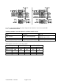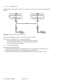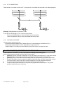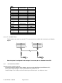
1
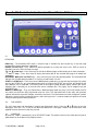
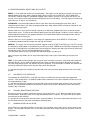
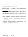
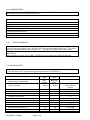
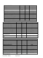
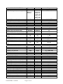
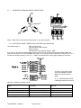
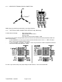
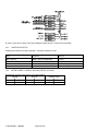
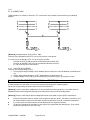
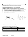
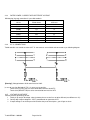
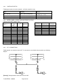
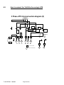
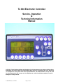
Te 804 Electronic Controller Service, Operation & Technical Information Manual WARNING! Technical descriptions and data given in this document are accurate, to the best of our knowledge, but can be subject to change without prior notice so no liabilities for errors, omissions or contingencies arising there from are accepted. Moreover, the TE804 should be set up and used by trained personnel and, in any case, in compliance to current installation standards, to avoid damages or safety hazards. Te 804 REV02sas 10-4-2004 Page 1 of 38 1. OPERATING PROCEDURES FOR AUTOMATIC CONTROL PANEL [Warning!] Carefully study the instructions of your automatic control panel before starting your Genset set, so you will be able to operate your Genset safely. [Warning!] Before starting your generator, check that there are no obstructions around it. [Caution!] When starting the Genset the first time or after a long storage, let the engine warm up at least 5 minutes. This prolongs the life of the Genset. [Warning!] The automatic control panel should only be set up and operated by trained personnel. Local codes must be followed in order to avoid equipment damage, and /or personal injury up to and including death. [Caution!] Always check that the technical data printed on the nameplate corresponds to your specific requirements. These products have been manufactured to minimize RFI that could damage or interfere with equipment. Note: Due to a constant drive to improve the product through research and development, all procedures, specifications and equipment are subject to change without notice. 1.1 OPERATING PROCEDURES - GENERAL - • • • • • • • 1.2 Trained personnel should do programming of the control panel. Any programming done to the control panel should be performed with the Engine off and the load disconnected. Electrical connections must be carried out in compliance with local codes. AC cables, particularly, must be sized and placed so that the cable does not attain temperatures over 50° C Ambient temperature. It is necessary to check that cables have not loosened at the respective terminals and to remove any dust or other materials that have fouled the control panel during installation. The cleaning must be done by means of a vacuum, avoiding blowing dust into the control panel with air. Connections to the terminal board must be made using a cable of correct cross section, per electric diagram. To open the control panel front door use the special key supplied with the control panel. Only trained personnel should have access to this key. To protect from electric shocks and any atmospheric discharges, it is necessary to provide adequate earthen ground. TECHNICAL TERM DEFINITION Refer to the following definitions whenever these terms are mentioned in the manual: Set-up: This is the set up of the controller. This is done before or during the installation of the Genset. There are three different menus in order to have access to the parameters setting and relative data. All operating times and calculations that affect the system functioning can be set up and the parameters are stored in a permanent memory. Only trained personnel can reach this function and it is password protected. Starting Cycles: The sequence of diesel Genset starting is as follows: First glow plugs are energized (programmable duration), and then the fuel solenoid valve is activated. After these two steps the control panel enters into a start interval (programmable duration), alternating with intervals of cool down (programmable duration). Once the engine is on, the starting attempts stop immediately. The sequence of gaseous Genset starting is as follows: First the gas valve is activated; for the first starting attempt primer is energized. The Electronic Ignition is energized at the same time as the gas Te 804-REV02 – 10/04/04 Page 2 of 38 valve; to avoid over-speed alarm RPM governor (this device is described in Appendix B) is energized after a time delay (after cranking). After these steps the control panel enters into a start interval (programmable duration), alternating with intervals of cool down (programmable duration). Once the engine is on, the starting attempts stop immediately. Genset Stopping Procedure: The transfer switch opens and the Genset continues to run for a cool down period (programmable) at the end of which the fuel solenoid valve or the gas valve + Electronic Ignition + rpm governor are switched off and the engine stops. In case of emergency stop, the above-mentioned procedure takes place without considering the cool down time. Engine On: The engine is considered on when the “engine ON “signal, which comes out of the engine alternator battery charger, exceeds the programmed value. Its led shows the engine-on signal. For safety reason generator output voltage is also monitored to verify that the engine is running. Alarms On: Oil pressure and high temperature alarms are enabled after a delay time (programmable) greater than the engine-on signal time. The “engine ON” led flashing indicates the engine is on but the alarms are not enabled, and becomes on steady when the engine is running and the alarms are enabled. During the stopping cycle, the alarms are disabled and the fuel solenoid valve close simultaneously. Utility-Off: The utility-off signal occurs when the utility voltage / frequency is out of the fixed limits (lower than the minimum fixed values or higher than the maximum fixed values) and remains in that state longer than the programmable time. This causes the transfer switch to transfer to the emergency position (after the Generating set has started and met requirements). Utility-On: In the same way, the utility-on signal occurs when (as a programmable time is exceeded) the voltage / frequency are inside the fixed limits. The transfer switch function will depend on the selected operating procedure. Generator-On: Generator-On signal works as the utility-on signal described above. Frequencies and delay intervals are independent. The Voltages / Utility/Genset and Generator/Utility Switching: The remote control switches between the utility and Genset. A delay time occurs to avoid simultaneous connections. 1.3 OPERATING MODES Note: Please refer to Te804 controller instructions if you need more information. The digital controller has 4 different modes: Reset Automatic Manual Test You select the mode you need by pressing the corresponding button and its LED lights up. It is always possible to skip from one operating procedure to another. Warning! For safety reasons, on controller power-up, the operating Mode will always be RESET. When one of the four operating Mode LED’s is flashing, it indicates that the unit is being controlled by a supervision system (remote control). Te 804-REV02 – 10/04/04 Page 3 of 38 2. Te 804 Controller Instructions for HS and Master GU Series 2.1 KEYBOARD HELP key – The illuminated LED means a help message is available. By pressing the key, a help message concerning the current operation is displayed. ENTER and EXIT keys - Press ENTER to confirm operations or to enter the menu. Press EXIT to refuse an operation or to exit a menu and help message. ⇓” and “⇑ ⇑” arrow keys – Press these keys to shift to the different pages of data display or to select parameters. “⇓ “–“ and “+” keys – Press these keys to display alternative data of the selected data page or to modify the parameters. OFF/RESET, MAN, AUT and TEST keys – Press these keys to select the operating mode. The illuminated LED indicates the selected operating mode; if it is flashing, remote control is active. START and STOP keys – These keys work in MAN operating mode only, to start and stop the engine. By quickly pressing the START key, one start attempt takes place; by keeping the START key pressed, the duration of the start attempts can be extended. The flashing LED of the engine symbol denotes engine started, with alarms inhibited; and is constantly on at the end of the alarms inhibition time. The engine can be stopped using the OFF/RESET key. MAINS and GEN keys – They are enabled only in MAN operating mode only, they are used to control the ATS and switch the load from utility to generator and vice versa. The illuminated Leds of the utility and generator symbols indicate the respective voltages are within preset limits. The illuminated Leds of the changeover symbols indicate the actual closing of switching devices; when flashing, there is a incorrect feed-back signal for the actual closing or opening of the switching devices. 2.2 LCD SCREEN ⇓” or “⇑ ⇑” keys to view the The LCD shows data and information in graphic and alphanumeric forms. Press the “⇓ data pages. Press the “–“or “+” keys to see alternative data on the same page. Te804 is set to return to the main page 60 seconds after the last key was pressed. 2.3 POWER-UP At power-up, Te804 is automatically set to OFF/RESET mode. The option to return to the mode present prior to power down can be enabled in the program section. Te 804-REV02 – 10/04/04 Page 4 of 38 2.4 OPERATING MODES: RESET, MAN, AUT and TEST RESET: In reset mode, the controls are not operational. The engine can not operate. If the utility is present, the load will default to the utility. When changing modes with the engine running from TEST, AUT or MAN to the OFF/RESET mode the engine is immediately stopped and the alarms are reset. If the cause of the alarm is still present, it can not be reset and will continue to be displayed on the LCD display. The LCD display will continue to show measures as well as any valid alarms. AUTOMATIC: In the Automatic mode the Genset starts when the utility voltage goes out of limits and its respective control switch is off. After the (programmed) delay, Utility remote control switch gets switched off and the Genset start cycle begins. When the Genset is running and its voltage / frequency are within the (programmed) limits, the Genset remote control switch closes. The Genset will continue operating until the utility voltage is restored. Once the utilities are within (programmed) limits for the (programmed) time, the remote control switches exchange position, and the Genset carries out the stop cycle. When the Genset is running, however, it can always be stopped by means of the RESET or STOP buttons. In automatic procedure both the remote start and stop are enabled. MANUAL: The engine can be manually started or stopped using the START and STOP keys. The ATS can only be switched by holding down on the Manual key and then pressing the MAINS or the GEN keys. Keeping the key pressed for an extended time can prolong the preset starting time. Keeping the Stop key pressed for more than 6 seconds will result in the fuel valve being disabled for 4 minutes. The start button begins the start cycle while the stop button begins the stop cycle. After pushing the stop button you can stop it from beginning the stop cycle by immediately pushing the start button. TEST: In test mode the Genset begins the start cycle (even if the utility is present). If the Utility power drops out while the Genset is in test mode the controller will over ride this function and switch the Generator to the load. Once the Utility voltage returns, the load will stay on the generator. If the auto mode is enabled, the controller will transfer the load to the Utility and will start the stop cycle of the generator. It is possible to program the controller so that the load will be transferred from utility to Genset even if the utility is present. 2.5 AUTOMATIC TEST (EXERCISE) The automatic test (EXERCISE) is a periodic check that is carried out by the control panel at programmed intervals. If the control panel is in automatic mode and the automatic test has been enabled, the Genset runs for a fixed period before it stops. It is possible to program the controller so that the load will be transferred from utility to Genset even if the utility is present. It is also possible to program the controller in order to carry out the automatic test even if the external (remote) stop is activated. 2.6 PERIODIC MAINTENANCE INTERVAL By means of set up, a periodic maintenance interval, expressed in hours, is set. When the working hours reach the fixed amount, the display shows a message noting maintenance is required. The System will not shut down and continues to work normally. It is possible to reset anytime the remaining hours (Command Menu). This means that periodic maintenance can be carried out before the end of the fixed amount of working hours. 2.7 WORKING HOUR CALCULATION As the Engine runs the working minutes are counted. The calculation, expressed in hours, can be shown on the display. The calculation continues even in case of disconnection of the electrical input and cannot be set to zero by the user. Te 804-REV02 – 10/04/04 Page 5 of 38 2.8 ALARMS When an alarm arises, the alarm is displayed in the lower section of the display. In case of two alarms or more, they are individually shown in sequence. A help message is available for every alarm, to assist in locating the possible alarm source. Alarm conditions can be reset by means of the OFF/RESET key; this is to prevent any unintentional engine starting during alarm conditions. If the alarm does not reset, this means the cause of the alarm is still present. During event-log sessions and set-up operations, no alarms are displayed. 2.9 ALARM PROPERTIES Eight different properties can be assigned to each user alarm, including User Alarms: Alarm enabled. If not enabled, the alarm will not work. Retentive alarm. The alarm is latched even if the cause of the alarm is removed. Global alarm. It activates the output assigned to this function. Siren. It activates the output assigned to this function. Immediate Engine shutdown. Shutdown with Engine cool-down. Active only with engine running. Modem auto-call. A modem connection is performed according to the modality scheduled by preset parameters. All these properties are preset to a default value for the specific applications (Diesel or Gaseous Generating set). To change these properties, enter the ADVANCED MENU, find the ALARMS menu, press the “⇓” or “⇑” key to select the alarm, press the “-“or “+” key to select the property and then press the ENTER key to enable or disable the property. Press the EXIT key to return to the previous menu. [Warning!] Changing the Alarm Properties could result in equipment damage or personal injury and loss of warranty coverage. 2.10 SET-UP VIA KEYBOARD There are three different menus in order to have access to the parameters setting and related data. User’s menu: Access the setting of those parameters that final user can modify. To enter the menu, press the OFF/RESET key for 5 seconds then release it. Commands menu: Access to data resetting, parameter copy and their restore. It is necessary to access this menu for maintenance hours reset. To enter the menu, press the OFF/RESET key and simultaneously the ENTER key for 5 seconds and then release them. Press the EXIT key to exit the menu. Advanced menu: Access to all parameters setting. This menu is protected by a password. To enter the menu, keep the OFF/RESET key pressed, then push, in the following sequence, “-“ key twice, “+” key three times and “⇓” key four times then finally release the OFF/RESET key. [Warning!] Only trained personnel should do the parameters set-up. Changing the Set up Values could result in equipment damage or personal injury and loss of warranty coverage. Moving within the menu: After entering the menu, press the “⇓” or “⇑” keys to select a sub-menu (or a command in the case of “Commands menu”). Press the ENTER key to access parameter setting (or to perform the command). Press “⇓” or “⇑” keys to select the parameter and press “–“or “+” to modify it. Press the EXIT key to close the sub-menu and push it again to close the set-up. Data safety copy: A safety copy of the adjustable keyboard set-up data can only be made in Te804 flash memory. The same data can be restored, whenever required, to Te804 work memory. The commands and data restore of the safety copy are available in the Commands menu. Te 804-REV02 – 10/04/04 Page 6 of 38 2.11 SET-UP BY MEANS OF PERSONAL COMPUTER (PC) The set-up can be more easily done/ modified via PC connected to Te804 RS-232 port. Using the software setup, it is possible to transfer parameters (previously set) from Te804 to the PC and vice versa. In addition to the parameters set-up, with the PC it is possible to define: Help text of the alarms, descriptions and help text of the User Alarms. All the data related to the curve characteristic of the pressure, temperature, fuel level sensors and generator thermal protection. Custom logo, that appears on the display at power-up and at set-up exit via keypad. An information page, where one can write information, data, characteristics, etc., concerning a certain application. 2.12 RECOMMENDATIONS ABOUT SET-UP Safety copy of set-up data: It is highly recommended to save the set-up data on the PC hard disk and make a safety copy on floppy disk because of the large amounts of data involved with Te804 set-up. Moreover, it is advisable to update set-up data files each time data parameters are adjusted via keyboard. Bear in mind that a safety copy of adjustable keyboard set-up data can only be made in Te804 flash memory. This same data can be restored, whenever required, to Te804 work memory. The commands of safety copy and data restore are available in the commands menu. 2.13 DIGITAL PROGRAMMABLE INPUTS AND OUTPUTS All the outputs and a part of the inputs are assigned (set) to specific functions depending on specific application. See the table in the following pages. To change the function assignment, enter INPUTS or OUTPUTS menu, press the “⇓” or “⇑” keys to select the exact input or output and press “–“or “+” keys to select the function. The following properties can be assigned to each input: NO (Normally Open), command at the input contact closing or NC (Normally closed), command at the input contact opening Delay before the contact closes Delay before the contact opens To set these properties, enter the INPUTS menu, press the “⇓” or “⇑” key to select the exact input, press the ENTER key to access the parameter properties, press the “⇓” or “⇑” key to select the parameter property and then “–“or “+” key to change it. Press the EXIT key to return to the previous menu. Te 804-REV02 – 10/04/04 Page 7 of 38 2.14 COMMANDS MENU To enter the menu, press the OFF/RESET key and simultaneously the ENTER key for 5 seconds and then release them. Press the EXIT key to exit the menu. C01 Energy meter reset C02 Maintenance reset C03 Engine hour meter reset C04 Starting counter reset C05 Parameters to default C06 Save parameters to flash C07 Load parameters from flash C08 Rent hours reset 2.14.a HIDDEN COMMANDS Maintenance hour counter setting To set the maintenance counter, press the OFF/RESET key and subsequently, ENTER and “⇓” keys for 5s; after that release them. Set the hours using the “-“or “+” key and press the EXIT key to store and exit. RPM / W ratio When the engine is running, press START + ENTER keys to self-configure the RPM / W ratio value. 2.15 ADVANCED MENU To enter the menu, keep the OFF/RESET key pressed, then push, in the following sequence, “-“ key twice, “+” key three times and “⇓” key four times then finally release the OFF/RESET key. Default HS “01” UTILITY (LANGUAGES) HS= Home StandBy D= Diesel Units, G= Gaseous Units, P0101 Languages P0102 Year P0103 Month P0104 Day of the month P0105 Day of the week P0106 Hour P0107 Minutes P0108 Seconds P0109 Clock setting at power-up P0110 Default page return (s) P0111 Display contrast (%) Te 804-REV02 – 10/04/04 Page 8 of 38 Default GU Range GU= Masters GU Series English English ON 60 50 OFF 60 50 English/Italian/ French/German/ Spanish 1989-2089 1-12 1-31 1-7 0-23 0-59 0-59 OFF/ON OFF/5-999 0-100 “02” GENERAL Default HS P0201 CT ratio 20.0 P0202 VT ratio P0203 Wiring configuration P0204 Rated voltage (V) P0205 Frequency (Hz) P0206 RPM / “W” ratio 1.0 L1-L2-L3-N 208 60 D=4.444 G=29.464 D=1800 G=2400 °F/psi 0.5 5 ON OFF OFF P0207 Rated engine speed (RPM) P0208 Unit of measure P0209 MAINS/GEN interlock (s) P0210 M/G feedback delay (s) P0211 RESET mode at power-up P0212 Siren time (s) P0213 Siren before starting (s) Default GU GU26L=10 GU30J=16 GU42J=16 GU65J=20 GU85J=30 GU105J=30 GU125J=50 1.0 L1-L2-L3-N 208 60 Range 1.0-2000.0 1.0-500.0 3N-3-2N-1N 100-50000 50/60 0.001-50.000 1800 750-3600 °F/psi 0.5 5 ON 5 5 °C/bar-°F/psi 0.0-60.0 1-60 OFF/ON OFF/1-60 OFF/1-60 Caution! The calculation system of the TE804 can handle power value up to 999 000 000 VA (999MVA). “03” BATTERY P0301 Battery voltage (V) P0302 MAX voltage limit (%) P0303 MIN voltage limit (%) P0304 MIN/MAX voltage delay (s) “04” ENGINE STARTING P0401 Alternator voltage engine started (V) P0402 Generator voltage engine started (%) P0403 Generator frequency engine started (%) P0404 “W” signal engine started(RPM) P0405 Glow-plugs preheating (s) P0406 Starting attempts number P0407 Attempts starting time(s) P0408 Pause between starting(s) P0409 Aborted starting & subsequent(s) P0410 Deceleration time (s) P0411 Cooling time (s) P0412 Stop magnet time (s) P0413 Gas valve delay (s) P0414 Priming time (s) P0415 Choke valve time (s) P0416 Choke OFF limit (%) Te 804-REV02 – 10/04/04 Default HS Default GU Range 12 130 75 10 12 130 75 10 12/24 110-140% 60-100% 0-30 Default HS Default GU Range 6 20 20 20 8 5 8 10 3 OFF 10 OFF OFF D=OFF G=1 OFF 5 6 20 20 20 8 5 8 10 3 OFF 10 OFF OFF OFF OFF/3-30 OFF/10-100% OFF/10-100% OFF/10-100% OFF/1-60 1-10 1-30 1-30 OFF/1-20 OFF/1-180 1-3600 OFF/1-60 OFF/1-10 OFF/1-10 OFF 5 OFF/1-10 0-100 Page 9 of 38 “05” ENGINE CONTROL P0501 Pressure sensor selection P0502 Temperature sensor selection P0503 Fuel sensor selection P0504 MIN pressure warning P0505 MIN pressure limit P0506 MAX temperature warning P0507 MAX temperature limit P0508 MIN fuel warning (%) P0509 MIN fuel level (%) P0510 Alarms inhibition at starting (s) P0511 MAX “W” speed limit (%) P0512 MAX “W” speed delay (s) P0513 MIN “W” speed limit (%) P0514 MIN “W” speed delay (s) Default HS Default GU Range VEGLIA VEGLIA D=DATCOM G=OFF 11.6 4.4 203 230 20 10 8 110 3 90 5 VEGLIA VEGLIA DATCOM (1) (1) (1) 11.6 4.4 203 230 20 10 8 110 3 90 5 0.1-180.0 0.1-180.0 40-285 40-285 0-100 0-100 1-30 100-120 3-20 80-100 0-600 “06” MAINS CONTROL Default HS Default GU Range P0601 MIN voltage limit (%) P0602 MIN voltage delay (s) P0603 MAX voltage limit (%) P0604 MAX voltage delay (s) P0605 MAINS into limits delay(s) P0606 MIN/MAX hysteresis limits (%) P0607 MAX asymmetry limit (%) P0608 MAX asymmetry delay (s) P0609 MAX frequency limit (%) P0610 MIN frequency limit (%) P0611 MIN/MAX frequency delay (s) P0612 MAINS control OFF/internal/external) P0613 MAINS control in RESET/OFF mode P0614 MAINS control in MAN mode 90 5 110 5 10 3.0 15 5 103 97 5 INTERNAL 90 5 110 5 10 3.0 15 5 103 97 5 INTERNAL 70-100 0-600 100-120 0-600 1-600 0.0-5.0 5-20 0-600 100-120/OFF OFF/80-100 0-600 OFF/INT/EXT OFF OFF OFF/ON/OFF+GLOB/ON+GLOB OFF OFF OFF/ON/OFF+GLOB/ON+GLOB Note! The phase sequence control can be enabled by means of the alarm properties table menu. “07” GEN CONTROL Default HS Default GU Range P0701 MIN voltage limit (%) P0702 MIN voltage delay (s) P0703 MAX voltage limit (%) P0704 MAX voltage delay (s) P0705 Generator into limits delay (s) P0706 MIN/MAX hysteresis limits (%) P0707 MAX asymmetry limit (%) P0708 MAX asymmetry delay (s) P0709 MAX frequency limit (%) P0710 MAX frequency delay (s) P0711 MIN frequency limit (%) P0712 MIN frequency delay (s) P0713 Gen. Control (OFF/internal/external) 90 5 110 5 10 3.0 15 5 105 3 95 5 INTERNAL 90 5 110 5 10 3.0 15 5 110 0 95 5 INTERNAL 70-100 0-600 100-120 0-600 0-600 0.0-5.0 5-20 0-600 100-120/OFF 0-200 OFF/80-100 0-600 OFF/INT/EXT Te 804-REV02 – 10/04/04 Page 10 of 38 “08” GENERATOR PROTECTION Default HS Default GU Range OFF/5-10000 250 3 P3 20 GU26L=85 GU30J=94 GU42J=132 GU65J=212 GU85J=257 GU105J=344 GU125J=386 250 3 P3 20 Default HS Default GU Range MONDAY 12 0 MONDAY 12 0 1-7 00-23 00-59 07 07 1-30 OFF OFF 50 OFF OFF 50 OFF/1-60 OFF/ON OFF/1-999 OFF OFF OFF/ON Default HS Default GU Range P1001 Serial port address P1002 RS-232 baud rate P1003 RS-485 baud rate P1004 Modem channel 01 9600 OFF RS232 01 9600 OFF RS232 1-99 OFF/1200-38400 OFF/1200-38400 RS232/RS485 “11” MISCELLANEOUS Default HS Default GU Range OFF 0 0 0 0 OFF 0 0 0 0 OFF NORMAL 25 5 OFF OFF 0 0 0 0 OFF 0 0 0 0 OFF NORMAL 25 5 OFF OFF/ON 0-9999 0-999 0-9999 0-999 OFF/ON 0-9999 0-999 0-9999 0-999 0-60000 Normal/EJP/EJP-T/SCR 0-99 0-30 OFF/ON P0801 Rated generator current (A) D=76.3 NG=62.5 LPG=69 P0802 MAX current limit (%) P0803 MAX current delay (s) P0804 Thermal protection curve selection P0805 Generator protection reset time (s) “09” EXERCISE AND MAINTENANCE P0901 EXERCISE beginning day P0902 EXERCISE beginning hour (h) P0903 EXERCISE beginning Minutes (m) P0904 Interval between EXERCISES (days) P0905 EXERCISE duration (m) P0906 EXERCISE with load P0907 Maintenance interval (h) P0908 EXERCISE with remote / external stop “10” COMUNICATION PORT P1101 Max engine power starting P1102 Engine start threshold (kW) P1103 Engine start threshold delay (s) P1104 Engine stop threshold (kW) P1105 Engine stop threshold delay (s) P1106 Dummy load P1107 Dummy load ON (kW) P1108 Dummy load ON delay (s) P1109 Dummy load OFF (kW) P1110 Dummy load OFF delay (s) P1111 Rent hours (h) P1112 Mode select P1113 Start motor delay P1114 Changeover delay P1115 Changeover block Te 804-REV02 – 10/04/04 Page 11 of 38 100-500/OFF 0.0-60.0 (1) 0-5000 “12” PROGRAMMABLE INPUTS Default HS Default GU Range P1201 Input terminal 8.1 8.1 Contact type 8.1 Opening delay (s) 8.1 Closing delay (s) P1202 Input terminal 8.2 EMERG. STOP NC 0.0 0.0 REMOTE STAR. (1) NO/NC 0.0-6000.0 0.0-6000.0 (1) 8.2 Contact type 8.2 Opening delay (s) 8.2 Closing delay (s) P1203 Input terminal 8.3 8.3 Contact type 8.3 Opening delay (s) 8.3 Closing delay (s) P1204 Input terminal 8.4 8.4 Contact type 8.4 Closing delay (s) 8.4 Opening delay (s) P1205 Input terminal 8.5 8.5 Contact type 8.5 Closing delay (s) 8.5 Opening delay (s) P1206 Input terminal 8.6 EMERG. STOP NC 0.0 0.0 REMOTE STAR. NO 0.0 0.0 DISABLED NO 0.0 0.0 DISABLED NO 0.0 0.0 DISABLED NO 0.0 0.0 REMOTE STOP NO 0.0 0.0 DISABLED NO 0.0 0.0 UA1 NO 0.0 0.0 UA2 NO 0.0 0.0 D=DISABLED G=Remote Stop NO NO 0.0 0.0 0.0 0.0 DISABLED DISABLED NO NO 0.0 0.0 0.0 0.0 DISABLED DISABLED NO NO 0.0 0.0 0.0 0.0 DISABLED DISABLED NO NO 0.0 0.0 0.0 0.0 WATER TEMP. WATER TEMP. NO NO 0.0 0.0 0.0 0.0 OIL PRESSURE OIL PRESSURE NC NC 1.0 1.0 1.0 1.0 FUEL LEVEL FUEL LEVEL NO NO 0.0 0.0 0.0 0.0 8.6 Contact type 8.6 Closing delay (s) 8.6 Opening delay (s) P1207 Input terminal 8.7 8.7 Contact type 8.7 Closing delay (s) 8.7 Opening delay (s) P1208 Input terminal 8.8 8.8 Contact type 8.8 Closing delay (s) 8.8 Opening delay (s) P1209 Input terminal 8.9 8.9 Contact type 8.9 Closing delay (s) 8.9 Opening delay (s) P1210 Input terminal 9.1 9.1 Contact type 9.1 Closing delay (s) 9.1 Opening delay (s) P1211 Input terminal 9.2 9.2 Contact type 9.2 Closing delay (s) 9.2 opening delay (s) P1212 Input terminal 9.3 9.3 Contact type 9.3 Closing delay (s) 9.3 Opening delay (s) (1) See the list of the available functions in the “Programmable inputs” table. Programmable inputs – (Function…) Disable Oil pressure Engine temperature Te 804-REV02 – 10/04/04 Page 12 of 38 NO/NC 0.0-6000.0 0.0-6000.0 (1) NO/NC 0.0-6000.0 0.0-6000.0 (1) NO/NC 0.0-6000.0 0.0-6000.0 (1) NO/NC 0.0-6000.0 0.0-6000.0 (1) NO/NC 0.0-6000.0 0.0-6000.0 (1) NO/NC 0.0-6000.0 0.0-6000.0 (1) NO/NC 0.0-6000.0 0.0-6000.0 (1) NO/NC 0.0-6000.0 0.0-6000.0 (1) NO/NC 0.0-6000.0 0.0-6000.0 (1) NO/NC 0.0-6000.0 0.0-6000.0 (1) NO/NC 0.0-6000.0 0.0-6000.0 Fuel level Emergency stop Remote stop Remote starting Remote starting without cooling Automatic test start Generator protection Supervision Off Setup block External MAINS control External GEN control Automatic changeover MAINS contactor feed-back GEN contactor feed-back Fuel tank too empty Fuel tank empty Fuel tank filled Fuel tank too full User’s alarm 1 User’s alarm 2 User’s alarm 3 User’s alarm 4 “13” PROGRAMMABLE OUTPUTS P1301 Output terminal 5.3 (Function...) P1302 Output terminal 6.2 (Function...) P1303 Output terminal 6.3 (Function...) P1304 Output terminal 6.5 (Function…) P1305 O-A.6 P1306 O-A.8 Default HS Default GU GLOBAL ALARM D=SIREN G=PRIMING VALVE D=GLOW-PLUGS G= N/A D=FUEL VALVE G= GAS VALVE Disabled Disabled GLOBAL ALARM (1) FUEL VALVE (1) Programmable outputs – (Function…) Te 804-REV02 – 10/04/04 Page 13 of 38 (1) (1) SIREN GLOW-PLUGS (1) See the list of the available functions in the “Programmable outputs” table. Disable Global alarm Fuel solenoid valve Siren Decelerator Stop magnet Glow-plugs Gas valve Air valve Priming valve Filling pump Dummy load A1-A43 and UA1-UA4 alarms Range Engine temperature warning (analog sensor) High engine temperature (analog sensor) Temperature analog sensor fault High engine temperature (digital sensor) Oil pressure warning (analog sensor) Low oil pressure (analog sensor) Pressure analog sensor fault Low oil pressure (digital sensor) Pressure digital sensor fault Fuel level warning(analog sensor) Low fuel level(analog sensor) Level analog sensor fault Low fuel level(digital sensor) High battery voltage Low battery voltage Inefficient battery Charger alternator failure “W” signal failure Low engine “W” speed High engine “W” speed Starting failure Emergency stop Unexpected stop Engine stop failure Low generator frequency High generator frequency Low generator voltage High generator voltage Generator asymmetry Generator short-circuit Generator overload External generator protection tripping Incorrect generator phase sequence Incorrect utility phase sequence Wrong system frequency setting Generator contactor failure Utility contactor failure Maintenance requested System error Fuel transfer too empty Fuel transfer too full Rent hours exhausted User’s alarm 1 User’s alarm 2 (Dirty air filter) User’s alarm 3 User’s alarm 4 Te 804-REV02 – 10/04/04 Page 14 of 38 X X X X X X X X X X X X X X X X X X X X X X X X X X X X X X X X X X X X X X X X X X X X X X X X X X X X X X X X X X X X X X X X X X X X X X X X X X X X X X X X X X X X X X X X X X X X X X X X X X X X X X X Modem auto call X X X X X X X X X X X X X X X X X X X X X X X X X X X X X X X X X Active with engine running X X X X X X X X X X X X X X X X X X X X X X X X X X X X X X X X X Engine cool down X Engine shutdown X X Siren A01 A02 A03 A04 A05 A06 A07 A08 A09 A10 A11 A12 A13 A14 A15 A16 A17 A18 A19 A20 A21 A22 A23 A24 A25 A26 A27 A28 A29 A30 A31 A32 A33 A34 A35 A36 A37 A38 A39 A40 A41 A42 UA1 UA2 UA3 UA4 Global alarm List of the alarms for HSD Latched alarm Alarm properties ⇒ Alarm enabled 2.16 X X X X X X X X X X X X X X X X X X X X X X X X X X X X X X X X X X X X X X X X X X X X X Engine temperature warning (analog sensor) High engine temperature (analog sensor) Temperature analog sensor fault High engine temperature (digital sensor) Oil pressure warning (analog sensor) Low oil pressure (analog sensor) Pressure analog sensor fault Low oil pressure (digital sensor) Pressure digital sensor fault Fuel level warning(analog sensor) Low fuel level(analog sensor) Level analog sensor fault Low fuel level(digital sensor) High battery voltage Low battery voltage Inefficient battery Charger alternator failure “W” signal failure Low engine “W” speed High engine “W” speed Starting failure Emergency stop Unexpected stop Engine stop failure Low generator frequency High generator frequency Low generator voltage High generator voltage Generator asymmetry Generator short-circuit Generator overload External generator protection tripping Incorrect generator phase sequence Incorrect utility phase sequence Wrong system frequency setting Generator contactor failure Utility contactor failure Maintenance requested System error Fuel transfer too empty Fuel transfer too full Rent hours exhausted User’s alarm 1 User’s alarm 2 (Dirty air filter) User’s alarm 3 User’s alarm 4 Te 804-REV02 – 10/04/04 Page 15 of 38 X X X X X X X X X X X X X X X X X X X X X X X X X X X X X X X X X X X X X X X X X X X X X X X X X X X X X X X X X X X X X X X X X X X X X X X X X X X X X X X X X X X X X X X X X X X X X X X X X X X X X X X X X X X X X X X X X X X Modem auto call X X X Active with engine running X X X X X X X X X X X X X X X X X X X X X X X X X X X X X X X X X Engine cool down X X X X X X X X X X X X X X X X X X X X X X X X X X X X X X X X X Engine shutdown Siren A01 A02 A03 A04 A05 A06 A07 A08 A09 A10 A11 A12 A13 A14 A15 A16 A17 A18 A19 A20 A21 A22 A23 A24 A25 A26 A27 A28 A29 A30 A31 A32 A33 A34 A35 A36 A37 A38 A39 A40 A41 A42 UA1 UA2 UA3 UA4 Global alarm List of the alarms for HSG Latched alarm Alarm properties ⇒ Alarm enabled 2.17 X X X X X X X X X X X X X X X X X X X X X X X X X X X X X X X X X X X X X X X X Engine temperature warning (analog sensor) High engine temperature (analog sensor) Temperature analog sensor fault High engine temperature (digital sensor) Oil pressure warning (analog sensor) Low oil pressure (analog sensor) Pressure analog sensor fault Low oil pressure (digital sensor) Pressure digital sensor fault Fuel level warning(analog sensor) Low fuel level(analog sensor) Level analog sensor fault Low fuel level(digital sensor) High battery voltage Low battery voltage Inefficient battery Charger alternator failure “W” signal failure Low engine “W” speed High engine “W” speed Starting failure Emergency stop Unexpected stop Engine stop failure Low generator frequency High generator frequency Low generator voltage High generator voltage Generator asymmetry Generator short-circuit Generator overload External generator protection tripping Incorrect generator phase sequence Incorrect utility phase sequence Wrong system frequency setting Generator contactor failure Utility contactor failure Maintenance requested System error Fuel transfer too empty Fuel transfer too full Rent hours exhausted Low Radiator Level User’s alarm 1 User’s alarm 2 User’s alarm 3 User’s alarm 4 Te 804-REV02 – 10/04/04 Page 16 of 38 X X X X X X X X X X X X X X X X X X X X X X X X X X X X X X X X X X X X X X X X X X X X X X X X X X X X X X X X X X X X X X X X X X X X X X X X X X X X X X X X X X X X X X X X X X X X X X X X X X X X X X X X X X X X Modem auto call X X X X X X X X X X Active with engine running X X X X X X X X X X X X X X X X X X X X X X X X X X X X X X X X X Engine cool down X X X X X X X X X X X X X X X X X X X X X X X X X X X X X X X X X Engine shutdown Siren A01 A02 A03 A04 A05 A06 A07 A08 A09 A10 A11 A12 A13 A14 A15 A16 A17 A18 A19 A20 A21 A22 A23 A24 A25 A26 A27 A28 A29 A30 A31 A32 A33 A34 A35 A36 A37 A38 A39 A40 A41 A42 A43 UA1 UA2 UA3 UA4 Global alarm List of the alarms for GU Latched alarm Alarm properties ⇒ Alarm enabled 2.18 X X X X X X X X X X X X X X X X X X X X X X X X X X X X X X X 2.19 TECHNICAL CHARACTERISTICS Power supply Battery rated voltage 12 VDC Voltage range 9…15.6 VDC Minimum voltage at the starting 6.7VDC Maximum current consumption 320mA at 12VDC Stand-by current 150mA at 12VDC Micro interruption immunity 200ms Digital inputs Input type Negative Current input ≤10mA Input “low” voltage ≤1.5V (typical 2.9V) Input “high” voltage ≥5.3V (typical 4.3V) Input delay ≥50ms Speed input “W” Input type AC coupling Voltage range 5…50Vpp Frequency range 40…2000Hz Engine running input for pre-excited generator (D+) Voltage range 0…40VDC Maximum input current 12mA Maximum voltage at +D terminal 12 VDC (battery voltage) Pre-excitation current 170mA 12VDC Relay output 4.1-4.2 / 4.3-4.4 terminals (voltage free) Contact type 1 NC for utility + 1 NO for generator Rated voltage 250VAC (440VAC max) Rated current at 250VAC 8A AC1 (2A AC15) Relay output 5.3-5.4-5.5 terminals (voltage free) Contact type 1 changeover Rated voltage 250VAC max Rated current at 250VAC 8A AC1 (2A AC15) Relay output 6.2 / 6.3 / 6.4 / 6.5 terminals (+ battery voltage output) Contact type 1 NO Rated voltage 30VDC Rated current at 30VDC 5A DC1 Analog inputs Pressure sensor current 20mA max Temperature sensor current 7mA max Level sensor current 10mA max Analog ground voltage -0.5V…+0.5V Voltage inputs Maximum rated voltage 480VAC L-L (277VAC L-N) Measuring range 50…620V L-L (358VAC L-N) Frequency range 45…65Hz Measuring method True RMS Te 804-REV02 – 10/04/04 Page 17 of 38 Measuring input impedance Wiring mode Current inputs Rated current Ie Measuring range Measuring method Overload capacity Overload peak Power consumption >1.1MΩ L-L (>570kΩ L-N) 1, 2 or 3 phases, with or without neutral 5A 0.02…6A True RMS +20% Ie 50A for 1 second <0.3VA Measuring characteristics (-10…+45°C) Voltage ±1% ±1digit Frequency ±0.2% ±1digit Current ±1% ±1digit Power ±2% ±1digit Energy ±2% ±1digit Ambient operating conditions Operating temperature -20…+60°C Storage temperature -30…+80°C Relative humidity <90% Maximum pollution degree 3 Reference standards IEC/EN 60255-6, IEC 60664-1, IEC/EN 61000-4-5, IEC/EN 61000-4-4, IEC/EN 61000-4-3, IEC/EN 61000-4-6, IEC/EN 60255-22-2, IEC/EN 55011, IEC/EN 60255-21-2, IEC/EN 60068-2-6 (LROS-Lloyd’s Register Of Shipping), IEC/EN 60068-2-52 (RINA-Italian Naval Register), IEC/EN 60028-2-61 and IEC/EN 61010-1. 3. 3.1 CONNECTIONS INSTRUCTIONS (HS SERIES ONLY) LOW WYE (DOUBLE STAR) CONNECTIONS 120/208V 3PH (Factory Default) This is the “on factory set” connection. In order to verify /remake this connection it is necessary to proceed according to the following points. Do not run the generating set before all these steps have been checked / done. [Warning!] Internal connections modification can only be made by trained personnel. Local codes must be followed in order to avoid equipment damage, and /or personal injury up to and including death. [Warning!] Always check that the Genset voltage/connection corresponds to your specific requirements. Electrical connections must be carried out in compliance with local codes. AC cables, particularly, must be sized and placed so that the cable does not attain temperatures over 50° C Ambient temperatures. It is necessary to check that cables have not loosened at the respective terminals. To open the control panel front door use the special key supplied with the control panel. Only trained personnel should have access to this key. Te 804-REV02 – 10/04/04 Page 18 of 38 3.1.1 GENERATOR TERMINAL BOARD CONNECTIONS: Verify / modify internal terminal board connections as per above drawing. 3.1.2 ELECTRICAL PANEL CONNECTIONS (SEE B0172.dwg, B0192.dwg) To avoid damages to - Utility presence lamp Zero start device (block heater) Battery charger Other devices with maximum voltage = 240V it is necessary to maintain voltage between terminals 30 and 31 of internal terminal board between 208V and 240V. For this reason, in case of 120/208V connection it is necessary to connect terminal 31 with terminal 11 (L1) and terminal 30 with terminal 12 (L2) (V30-31 = 208V). All above devices will be supply between phase-phase. As soon as you connect utility verify input voltage on above devices: it must not exceed 240V. 13.1.3 CONTROLLER SETUP Following parameters have to be adjusted – verified on controller set-up: Menu Parameter Adjust to M02 - General P0203 – Wiring configuration P0204 – Nominal voltage (V) P0801 – Nom. Gen Current (A) L1-L2-L3-N 208 (or 220) See following table (Amax) M08 – Generator Protection Te 804-REV02 – 10/04/04 Page 19 of 38 3.1.3 RATED POWER / CURRENT WITH DIFFERENT VOLTAGE With low wye connection it is possible to obtain: Voltage VLL 208 3.1.4 HSD 22 VLN 120 Amax 76.3 KVA max 27.5 HSG 20 (LPG) Amax 69.4 KVA max 25 A.T.S. CONNECTIONS Te804 controller can control an external A.T.S.: two contacts are available and connected as per following diagram. [Warning!] Voltage between 42/44 and N is 120V. Carefully verify compatibility with ATS. If necessary connect a transformer. In case of use of an No Logic A.T.S. it is necessary to consider: Terminal 42 (UTILITY ON) has to be connected to terminal 30 of ATS Terminal 44 (GENSET ON) has to be connected to terminal 32 of ATS It is not necessary to use transformers 3.1.5 VOLTAGE ADJUSTMENT Carefully start the generating set and: 2 Check ph-ph and ph-N voltage: values between phase has not to be different (max difference= 2%) 2 Quickly adjust output voltage on “VOLT” potentiometer on generator A.V.R. 2 If output voltage is not inside preset limits before the preset time expires, you will get an alarm. 3.2 HIGH WYE (STAR) CONNECTIONS /240V-277/480V 3PH In order to obtain this connection it is necessary to proceed according to the following points. Do not run the generating set before all these steps have been done. [Warning!] Internal connections modification can only be made by trained personnel. Local codes must be followed in order to avoid equipment damage, and /or personal injury up to and including death. [Warning!] Always check that the Genset voltage/connection corresponds to your specific requirements. Electrical connections must be carried out in compliance with local codes. AC cables, particularly, must be sized and placed so that the cable does not attain temperatures over 50°C Ambient temperature. It is necessary to check that cables have not loosened at the respective terminals. To open the control panel front door use the special key supplied with the control panel. Only trained personnel should have access to this key. Te 804-REV02 – 10/04/04 Page 20 of 38 3.2.1 GENERATOR TERMINAL BOARD CONNECTIONS: Modify internal terminal board connections as per above drawing. 3.2.2 ELECTRICAL PANEL CONNECTIONS (SEE B0172.dwg, B0192.dwg) In order to do not damage - utility presence lamp zero start device (block heater) battery charger other devices with maximum voltage = 240V it is necessary to maintain voltage between terminals 30 and 31 of internal terminal board between 208V and 240V. For this reason: in case of 240/416V it is necessary to connect terminal 30 with terminal 14 (V30-31 = 240V). All above devices will be supply between phase-neutral. in case of 254/440V – 266/460V - 277/480V it is necessary to connect a suitable step-down transformer (transformer rated power Minimum 1.2kVA) As soon as you connect utility verify input voltage on above devices: it must not exceed 240V Te 804-REV02 – 10/04/04 Page 21 of 38 3.2.3 CONTROLLER SETUP Following parameters have to be adjusted – verified on controller set-up: Menu Parameter Adjust to M02 - General P0203 – Wiring configuration P0204 – Nominal voltage (V) P0801 – Nom. Gen Current (A) L1-L2-L3-N 440, or 460, or 480) See following table (Amax) M08 – Generator Protection 3.2.4 RATED POWER / CURRENT WITH DIFFERENT VOLTAGE With high wye connection it is possible to obtain: Voltage VLL 440 460 480 3.2.5 HSD 22 VLN 254 266 277 Amax 36.1 34.5 33.0 KVA max “ “ “ HSG 20 (LPG) Amax 32.8 31.4 30.0 KVA max “ “ “ A.T.S. CONNECTIONS Te804 controller can control an external A.T.S.: two contacts are available and connected as per following diagram. [Warning!] Voltage between 42/44 and N is 277V (with 480V Ph-PH). Carefully verify compatibility with ATS. If necessary connect a step-down transformer. In case of use of an No Logic A.T.S. it is necessary to consider: Terminal 42 (UTILITY ON) has to be connected to terminal 30 of ATS Terminal 44 (GENSET ON) has to be connected to terminal 32 of ATS It is necessary to use step-down transformers to reduce voltage up to 120V 3.2.6 VOLTAGE ADJUSTMENT Carefully start the generating set and: 1. Check ph-ph and ph-N voltage: values between phase have not to be different (max difference= 2%) 2. Quickly adjust output voltage on “VOLT” potentiometer on generator A.V.R. 3. If output voltage is not inside preset limits before the preset time expires, you will get an alarm. Te 804-REV02 – 10/04/04 Page 22 of 38 3.3 DOG LEG (ZIG ZAG) CONNECTIONS 120/240V 1ph In order to obtain this connection it is necessary to proceed according to the following points. Do not run the generating set before all these steps have been done. [Warning!] Internal connections modification can only be made by trained personnel. Local codes must be followed in order to avoid equipment damage, and /or personal injury up to and including death. [Warning!] Always check that the Genset voltage/connection corresponds to your specific requirements. 3.3.1 Electrical connections must be carried out in compliance with local codes. AC cables, particularly, must be sized and placed so that the cable does not attain temperatures over 50°C Ambient temperature. It is necessary to check that cables have not loosened at the respective terminals. To open the control panel front door use the special key supplied with the control panel. Only trained personnel should have access to this key. GENERATOR TERMINAL BOARD CONNECTIONS: Modify internal terminal board connections as per above drawing. 3.3.2 ELECTRICAL PANEL CONNECTIONS (SEE B0172.dwg, B0192.dwg) In order to do not damage - Utility presence lamp Zero start device (block heater) Battery charger Other devices with maximum voltage = 240V it is necessary to maintain voltage between terminals 30 and 31 of internal terminal board between 208V and 240V. For this reason, in case of 120/240V (1ph) connection it is necessary to connect terminal 31 with terminal 11 (L1) and terminal 30 with terminal 12 (L2) (V30-31 = 240V). All above devices will be supply between phasephase. Te 804-REV02 – 10/04/04 Page 23 of 38 As soon as you connect utility verify input voltage on above devices: it must not exceed 240V 3.3.3 CONTROLLER SETUP Following parameters have to be adjusted – verified on controller set-up: Menu Parameter Adjust to M02 - General P0203 – Wiring configuration P0204 – Nominal voltage (V) P0801 – Nom. Gen Current (A) L1-N-L2 240 See following table (Amax) M08 – Generator Protection 3.3.4 RATED POWER / CURRENT WITH DIFFERENT VOLTAGE With dog-leg (zig-zag) connection it is possible to obtain: Voltage VL1-L2 240 HSD 22 VLN 120 Te 804-REV02 – 10/04/04 Amax 88 KW max 21 Page 24 of 38 HSG 20 (LPG) Amax 75 KW max 18 3.3.5 A.T.S. CONNECTIONS Te804 controller can control an external A.T.S.: two contacts are available and connected as per following diagram. [Warning!] Voltage between 42/44 and N is 120V. Carefully verify compatibility with ATS. If necessary connect a transformer. In case of use of an No Logic A.T.S. it is necessary to consider: Terminal 42 (UTILITY ON) has to be connected to terminal 30 of ATS Terminal 44 (GENSET ON) has to be connected to terminal 32 of ATS It is not necessary to use transformers 3.3.6 VOLTAGE ADJUSTMENT Carefully start the generating set and: 1. Check ph-ph and ph-N voltage: values between phases-neutral has not to be different (max difference= 2%) 2. Quickly adjust output voltage on “VOLT” potentiometer on generator A.V.R 3. If output voltage is not inside preset limits before the preset time expires, you will get an alarm. 3.4 HIGH DELTA CONNECTIONS 240V 3ph - 120/240V 1ph In order to obtain this connection it is necessary to proceed according to the following points. Do not run the generating set before all these steps have been done. [Warning!] Internal connections modification can only be made by trained personnel. Local codes must be followed in order to avoid equipment damage, and /or personal injury up to and including death. [Warning!] Always check that the Genset voltage/connection corresponds to your specific requirements. Electrical connections must be carried out in compliance with local codes. AC cables, particularly, must be sized and placed so that the cable does not attain temperatures over 50° C Ambient temperatures. It is necessary to check that cables have not loosened at the respective terminals. To open the control panel front door use the special key supplied with the control panel. Only trained personnel should have access to this key. Te 804-REV02 – 10/04/04 Page 25 of 38 3.4.a HIGH DELTA CONNECTIONS 240V 3ph - 120/240V 1ph In order to obtain this connection it is necessary to proceed according to the following points. Do not run the generating set before all these steps have been done. [Warning!] Internal connections modification can only be made by trained personnel. Local codes must be followed in order to avoid equipment damage, and /or personal injury up to and including death. [Warning!] Always check that the Genset voltage/connection corresponds to your specific requirements. Electrical connections must be carried out in compliance with local codes. AC cables, particularly, must be sized and placed so that the cable does not attain temperatures over 50°C Ambient temperature. It is necessary to check that cables have not loosened at the respective terminals. To open the control panel front door use the special key supplied with the control panel. Only trained personnel should have access to this key. 3.4.1 GENERATOR TERMINAL BOARD CONNECTIONS: Modify internal terminal board connections as per above drawing. 3.4.2 ELECTRICAL PANEL CONNECTIONS (SEE B0172.dwg, B0192.dwg) In order to do not damage - utility presence lamp zero start device (block heater) battery charger other devices with maximum voltage = 240V it is necessary to maintain voltage between terminals 30 and 31 of internal terminal board between 208V and 240V. For this reason, in case of this connection it is necessary to connect terminal 31 with terminal 11 (L1) and terminal 30 with terminal 12 (L2) (V30-31 = 240V). All above devices will be supply between phase-phase. Te 804-REV02 – 10/04/04 Page 26 of 38 As soon as you connect utility verify input voltage on above devices: it must not exceed 240V 3.4.3 CONTROLLER SETUP Following parameters have to be adjusted – verified on controller set-up: Menu Parameter Adjust to M02 – General P0203 – Wiring configuration P0204 – Nominal voltage (V) M08 – Generator Protection P0801 – Nom. Gen Current (A) 3.4.4 RATED POWER / CURRENT WITH DIFFERENT VOLTAGE 240 3ph: L1-L2-L3 120/240V 1ph: L1-N-L2 240 See following table (Amax) With high delta connection it is possible to obtain: Voltage HSD 22 System 3ph L1-L2-L3 V 240 Amax 66.2 1ph L1-N-L2 VL1-L2=240V VL1-M=120V 88 44 L1-M Te 804-REV02 – 10/04/04 KVA max 27.5 KW max 21 5.3 Page 27 of 38 HSG 20 (LPG) Amax 60.1 75 37 KVA max 25 KW max 18 4.5 3.4.5 A.T.S. CONNECTIONS Te804 controller can control an external A.T.S.: two contacts are available and connected as per following diagram. [Warning!] Voltage between 42/44 and N is 120V. Carefully verify compatibility with ATS. If necessary connect a transformer. In case of use of a no logic A.T.S. it is necessary to consider: Terminal 42 (UTILITY ON) has to be connected to terminal 30 of ATS Terminal 44 (GENSET ON) has to be connected to terminal 32 of ATS it is not necessary to use transformers 3.4.6 VOLTAGE ADJUSTMENT Carefully start the generating set and: Check ph-ph and ph-N voltage: values between phase has not to be different (max difference= 2%) Quickly adjust output voltage on “VOLT” potentiometer on generator A.V.R. If output voltage is not inside preset limits before the preset time expires, you will get an alarm. Te 804-REV02 – 10/04/04 Page 28 of 38 4 4.1.0 CONNECTIONS INSTRUCTIONS (GU SERIES ONLY) LOW WYE (DOUBLE STAR) CONNECTIONS 120/208V 3PH (Factory Default) This is the “on factory set” connection. In order to verify /remake this connection it is necessary to proceed according to the following points. Do not run the generating set before all these steps have been checked / done. [Warning!] Internal connections modification can only be made by trained personnel. Local codes must be followed in order to avoid equipment damage, and /or personal injury up to and including death. [Warning!] Always check that the Genset voltage/connection corresponds to your specific requirements. Electrical connections must be carried out in compliance with local codes. AC cables, particularly, must be sized and placed so that the cable does not attain temperatures over 50° C Ambient temperatures. It is necessary to check that cables have not loosened at the respective terminals. To open the control panel front door use the special key supplied with the control panel. Only trained personnel should have access to this key. 4.1.1 GENERATOR TERMINAL BOARD CONNECTIONS: Verify / modify internal terminal board connections as per above drawing. 4.1.2 CONTROLLER SETUP Following parameters have to be adjusted – verified on controller set-up: Menu Parameter Adjust to M02 - General P0203 – Wiring configuration P0204 – Nominal voltage (V) P0801 – Nom. Gen Current (A) L1-L2-L3-N 208 See following table (Amax) M08 – Generator Protection 4.1.3 RATED POWER / CURRENT WITH DIFFERENT VOLTAGE With low wye connection it is possible to obtain: 208 VLL 120 VLN PO801 Amax KVA max GU26L GU30J GU42J 85 94 132 Te 804-REV02 – 10/04/04 31 34 48 Page 29 of 38 208 VLL 120 VLN GU65J GU85J GU105J GU125J PO801 Amax 212 257 344 368 KVA max 76 93 124 139 4.1.4 A.T.S. CONNECTIONS Te804 controller can control an external A.T.S.: two contacts are available and connected as per following diagram. [Warning!] Voltage between 42/44 and N is 120V. In case of use of an No Logic A.T.S. it is necessary to consider: Terminal 42 (UTILITY ON) has to be connected to terminal 30 of ATS Terminal 44 (GENSET ON) has to be connected to terminal 32 of ATS 4.1.5 VOLTAGE ADJUSTMENT Carefully start the generating set and: Check ph-ph and ph-N voltage: values between phase has not to be different (max difference= 2%) Quickly adjust output voltage on “VOLT” potentiometer on generator A.V.R. If output voltage is not inside preset limits before the preset time expires, you will get an alarm. 4.2 HIGH WYE (STAR) CONNECTIONS /240V-277/480V 3PH In order to obtain this connection it is necessary to proceed according to the following points. Do not run the generating set before all these steps have been done. [Warning!] Internal connections modification can only be made by trained personnel. Local codes must be followed in order to avoid equipment damage, and /or personal injury up to and including death. [Warning!] Always check that the Genset voltage/connection corresponds to your specific requirements. Electrical connections must be carried out in compliance with local codes. AC cables, particularly, must be sized and placed so that the cable does not attain temperatures over 50°C Ambient temperature. It is necessary to check that cables have not loosened at the respective terminals. To open the control panel front door use the special key supplied with the control panel. Only trained personnel should have access to this key. Te 804 REV02sas 10-4-2004 Page 30 of 38 4.2.1 GENERATOR TERMINAL BOARD CONNECTIONS: Modify internal terminal board connections as per above drawing. When the System is set up for 254/440V – 266/460V - 277/480V it is necessary to use a standard 2 wire logic ATS 4.2.2 CONTROLLER SETUP Following parameters have to be adjusted – verified on controller set-up: Menu Parameter Adjust to M02 - General P0203 – Wiring configuration P0204 – Nominal voltage (V) P0801 – Nom. Gen Current (A) L1-L2-L3-N 440, or 460, or 480) See following table (Amax) M08 – Generator Protection 4.2.3 RATED POWER / CURRENT WITH DIFFERENT VOLTAGE High wye connection Controller values : 440 VLL 254 VLN GU26L GU30J GU42J GU65J GU85J GU105J GU125J PO801 Amax 40 44 62 100 121 162 182 Te 804-REV02 – 10/04/04 KVA max 31 34 48 76 93 124 139 Page 31 of 38 460 VLL 266 VLN GU26L GU30J GU42J GU65J GU85J GU105J GU125J PO801 Amax 38 42 59 95 116 155 174 480 VLL 277 VLN GU26L GU30J GU42J GU65J GU85J GU105J GU125J KVA max 31 34 48 76 93 124 139 PO801 Amax 37 41 57 92 111 149 167 KVA max 30.8 33.8 47.5 76.3 92.5 123.8 138.8 4.2.4 A.T.S. CONNECTIONS Te804 controller can control an external A.T.S.: two contacts are available and connected as per following diagram. 4.2.5 When the System is configured for this voltage it is necessary to use a Standard 2 wire ATS. VOLTAGE ADJUSTMENT Carefully start the generating set and: Check ph-ph and ph-N voltage: values between phase have not to be different (max difference= 2%) Quickly adjust output voltage on “VOLT” potentiometer on generator A.V.R. If output voltage is not inside preset limits before the preset time expires, you will get an alarm. Te 804-REV02 – 10/04/04 Page 32 of 38 4.3 DOG LEG (ZIG ZAG) CONNECTIONS 120/240V 1ph In order to obtain this connection it is necessary to proceed according to the following points. Do not run the generating set before all these steps have been done. [Warning!] Internal connections modification can only be made by trained personnel. Local codes must be followed in order to avoid equipment damage, and /or personal injury up to and including death. [Warning!] Always check that the Genset voltage/connection corresponds to your specific requirements. 4.3.1 Electrical connections must be carried out in compliance with local codes. AC cables, particularly, must be sized and placed so that the cable does not attain temperatures over 50°C Ambient temperature. It is necessary to check that cables have not loosened at the respective terminals. To open the control panel front door use the special key supplied with the control panel. Only trained personnel should have access to this key. GENERATOR TERMINAL BOARD CONNECTIONS: Modify internal terminal board connections as per above drawing. 4.3.2 CONTROLLER SETUP Following parameters have to be adjusted – verified on controller set-up: Menu Parameter Adjust to M02 - General P0203 – Wiring configuration P0204 – Nominal voltage (V) P0801 – Nom. Gen Current (A) L1-N-L2 240 See following table (Amax) M08 – Generator Protection Te 804-REV02 – 10/04/04 Page 33 of 38 4.3.3 RATED POWER / CURRENT WITH DIFFERENT VOLTAGE With dog-leg (zig-zag) connection it is possible to obtain: 240 VL1-L2 120 VLN PO801 Amax 4.3.4 KVA max GU26L 103 24.6 GU30J 113 27 GU42J 158 38 GU65J 254 61 GU85J GU105J GU125J 308 412 465 74 99 111 A.T.S. CONNECTIONS Te804 controller can control an external A.T.S.: two contacts are available and connected as per following diagram. [Warning!] Voltage between 42/44 and N must be 120V. In case of use of an No Logic A.T.S. it is necessary to consider: Terminal 42 (UTILITY ON) has to be connected to terminal 30 of ATS Terminal 44 (GENSET ON) has to be connected to terminal 32 of ATS 4.3.5 VOLTAGE ADJUSTMENT Carefully start the generating set and: 1 Check ph-ph and ph-N voltage: values between phases-neutral has not to be different (max difference= 2%) 2 Quickly adjust output voltage on “VOLT” potentiometer on generator A.V.R 3 If output voltage is not inside preset limits before the preset time expires, you will get an alarm. Te 804-REV02 – 10/04/04 Page 34 of 38 4.4 HIGH DELTA CONNECTIONS 240V 3ph - 120/240V 1ph In order to obtain this connection it is necessary to proceed according to the following points. Do not run the generating set before all these steps have been done. [Warning!] Internal connections modification can only be made by trained personnel. Local codes must be followed in order to avoid equipment damage, and /or personal injury up to and including death. [Warning!] Always check that the Genset voltage/connection corresponds to your specific requirements. Electrical connections must be carried out in compliance with local codes. AC cables, particularly, must be sized and placed so that the cable does not attain temperatures over 50° C Ambient temperatures. It is necessary to check that cables have not loosened at the respective terminals. To open the control panel front door use the special key supplied with the control panel. Only trained personnel should have access to this key. 4.4a HIGH DELTA CONNECTIONS 240V 3ph - 120/240V 1ph In order to obtain this connection it is necessary to proceed according to the following points. Do not run the generating set before all these steps have been done. [Warning!] Internal connections modification can only be made by trained personnel. Local codes must be followed in order to avoid equipment damage, and /or personal injury up to and including death. [Warning!] Always check that the Genset voltage/connection corresponds to your specific requirements. Electrical connections must be carried out in compliance with local codes. AC cables, particularly, must be sized and placed so that the cable does not attain temperatures over 50°C Ambient temperature. It is necessary to check that cables have not loosened at the respective terminals. To open the control panel front door use the special key supplied with the control panel. Only trained personnel should have access to this key. 4.4.1 GENERATOR TERMINAL BOARD CONNECTIONS: Modify internal terminal board connections as per above drawing. Te 804-REV02 – 10/04/04 Page 35 of 38 4.4.2 CONTROLLER SETUP Following parameters have to be adjusted – verified on controller set-up: Menu Parameter M02 – General P0203 – Wiring configuration M08 – Generator Protection P0204 – Nominal voltage (V) P0801 – Nom. Gen Current (A) 4.4.3 240 3ph: L1-L2-L3 120/240V 1ph: L1-N-L2 240 See following table (Amax) RATED POWER / CURRENT WITH DIFFERENT VOLTAGE High delta connection Program values 1ph L1-N-L2PO801 120 VLN Amax 240VL1-L2 Current 240VL1-L2 GU26L 74 37 GU30J 81 41 GU42J 114 57 GU65J 184 92 GU85J 223 111 GU105J 298 149 GU125J 334 167 4.4.4 Adjust to KVA max 17.8 4.4 19.4 4.9 27.4 6.8 44.1 11 53.5 13.3 71.5 17.9 80.1 20 240 VLL 3ph L1-L2-L3 GU26L GU30J GU42J GU65J GU85J GU105J GU125J PO801 Amax KVA max 74 81 114 184 223 298 334 30.7 33.6 47.3 76.4 92.5 123.7 138.8 A.T.S. CONNECTIONS Te804 controller can control an external A.T.S.: two contacts are available and connected as per following diagram. [Warning!] Voltage between 42/44 and N must be 120V. Te 804-REV02 – 10/04/04 Page 36 of 38 4.4.5 VOLTAGE ADJUSTMENT Carefully start the generating set and: 1. Check ph-ph and ph-N voltage: values between phase has not to be different (max difference= 2%) 2 Quickly adjust output voltage on “VOLT” potentiometer on generator A.V.R. 3 If output voltage is not inside preset limits before the preset time expires, you will get an alarm. 5.0 5.1 ATS CONECTIONS How to program the TE804 to operate with an Intelligent ATS Program the Te 804 as follows: • Press and hold the Reset button • Press the “-“ button 2 times • Press the “+” button 3 times • Press the “down arrow” button 4 times • Release the Reset button This will place you in the Extended Menu • Scroll down (with the down arrow) to “M06 UTILITY CONTROL • Press Enter button • Scroll down to P0612 “MAINS control” • Right side will read “INTERNAL” • Press – button and this will change to “OFF” • Press the EXIT button You have now turned off the internal ATS control • Scroll down to “M12 Programmable input” • Press enter • Scroll down to “P1202 I8.2 Disabled” • Press the + button 6 times or until the “Disabled” changes to “Remote starting” • Press enter this will get you into the definition of the input change NA to NO • Press the Exit button 2 times • All the lights will blink and the Te 804 will restart with the changes in place This has programmed the 8.2 contact to be the remote Start input. The Remote start contact is 8.2 on the back of the Te 804 controller. Place the system in AUTO mode When 8.2 contact is shorted to ground the unit will start and run When 8.2 is disconnected from ground the unit will shut down Auto exercise will be enabled when the unit is in the AUTO mode Te 804-REV02 – 10/04/04 Page 37 of 38 5.2 How to connect the Te 804 to the no-logic ATS 3 Phase ATS Interconnection diagram (Z) LOAD N1 N2 N3 E1 Ground E2 E3 21 22 23 Normal Limit Switch NLS Emergency Limit Switch ELS Optional L1 L2 L3 11 12 13 N1 N2 N3 Neutral L1 L2 L3 30 32 = ATS connections 42 = Genset Connections Te 804-REV02 – 10/04/04 Page 38 of 38 44