1
.....
J
Model No. PFEL39030
Seriat No.
Serial_
Number
Decal
if you have questions, or if there
are missing parts, we will guarantee complete satisfaction
through direct assistance from
our factory.
TO AVOID DELAYS, PLEASE
CALL DIRECT TO OUR TOLLFREE CUSTOMER HOT LINE,
The trained technicians on our
customer hot line will provide
immediate assistance, free of
charge to you.
CUSTOMER
HOT LINE:
1°800°999°3756
Mon.=Fri.,
6 a.m.=6 p.m. MST
Patent Pending
CAUTION
Read all precautions and instructions in this manual before using
this equipment. Keep this manual for future reference.
, Visit our website
at
www.proform.com
new products,
prizes,
fitness tips, and much more!
TABLE OF CONTENTS
PROFORM is a registered trademark of iCON Health & Fitness, inc.
2
IMPORTANT
PRECAUTIONS
'_ WARN ING: Toreduce
theHskofseHou_
_.jury,
read
thefo.ow_ng
important precautionsbefore using the elliptical crosstrainer.
1. Read all instructions
in this manual before
using the elliptical crosstrainer,
2. It Is the responsibility
of the owner to ensure
that aH users of the ellipticaJ crosstrainer
are adequately informed of aH precautions,
3. The elliptical crosstrainer
is intended for
home use onlyo Do not use the elliptical
crosstrainer
in a commercial, rental, or institutional setting.
4.
Place the elliptical crosstrainer on a level
surface, with a mat beneath it to protect the
floor or carpet. Keep the elliptical crosstrain=
er indoors, away from moisture and dust,
5. Inspect and properly tighten aH parts regu=
ladyo Replace any worn parts immediately.
&
heart rate readings. The pulse sensor is
intended only as an exercise aid in determining heart rate trends in general
11. Keep your back straight when using the eIHptical crosstrainet;
do not arch your back,
t2. ifyou feel pain or dizziness while exercising, stop immediateJy and begin cooling
down.
13. When you stop exercising,
to slowly come to a stop.
allow the pedaJs
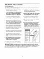
14. The decal shown below has been placed on
the eIHptical
crosstrainer,
ifthe decal is
missing, or if it is not legible, please call our
Customer Service Department toll-free at
1-800-999-3758 to order a free replacement
decal Apply the decal inthe locationshown.
Keep childrenunder i2 and pets away from
the elliptical
crosstrainerat aH times,
7. The eHiptica_
crosstrainer
should not be used
by persons weighing more than 250 pounds.
8_
Wear appropriate exercise clothes when
using the elliptical crosstrainero Nways wear
athletic
shoes forfoot protectionwhile exercising.
9.
Hold the handgdp puJse sensor or the bandJebars when mounting, dismounting,
or
using the elliptical crosstrainer.
10. The pulse sensor is not a medical device.
Various factors may affect the accuracy of
A WARN ING: Before
beginning
thisoranyexercise
program,
consuUf
yourphysician.
This is especiallyimportantfor persons over the age of 35 or persons with pre-existing
healthproblems, Read aH instructions
before using. ICON assumes no responsibility
for personaJ injury ot
propertydamage sustained by or through the use of thisproduct.
BEFORE YOU BEGIN
Congratulations for selecting the new PROFORM "_
800 CARDIO CROSSTRAINER. The PROFORM _'800
is an incredibly smooth exerciser that moves your feet
in a natural elliptical path, minimizing the impact on
your knees and ankles. And the unique PROFORM "_
800 features adjustable resistance and a statezoFthe z
art console to help you get the most from your exercise. Welcome to a whole new world of natural, elliptF
caFmotion exercise from PROFORM
questions after reading this manual, call our Customer
Service Department toIFfree at 1-800-999-3756,
Monday through Friday, 6 a.m. until 6 p.m. Mountain
Time (excluding holidays). To help us assist you,
please note the product model number and serial
number before calling. The model number is
PFEL39030. The serial number can be found on a
decal attached to the elliptical crosstrainer (see the
front cover of this manual for the location of the decal).
For your benefit, read this manuat carefully before
you use the ellipticaJ crosstrainer,
if you have
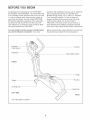
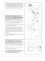
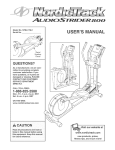
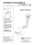
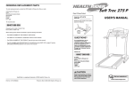
Before reading further, please familiarize yourself with
the parts that are labeled in the drawing below.
Handgdp
Pulse Sensor
Console
Handlebar
Water Bottle Holder*
FRONT
Pedal
Flex Bar
Wheel
Leveling Foot
l
_.,.,
Pedal Disk
LEFT SIDE
BACK
*No water bottle is included
4
Assembly requires two persons Place all parts of the elliptical crosstrainer in a cleared area and remove the
packing materials Do not dispose of the packing materials until assembly is completed In addition to the
included allen wrenches, assembly requires a phitlips screwdriver
_
_,
an adjustable
wrench __,
and a rubber mallet
J
E
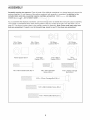
As you assemble the elliptical crosstrainer, use the drawings below to identify the small parts used in assembly
The number in parenthesis below each drawing refers to the key number of the part, from the PART LiST on
page 22 The second number refers to the quantity needed for assembly Note: Some smalm parts may have
been pre-assembled
If a part is not in the parts bag, check to see if it has been pre-assembled
M4 x 16mm
Screw (66)-=4
M4 x 22mm
Screw (93)-2
M8 Nylon
Locknut (46)-4
\_
Frame Spacer (83)-1
MI0 Split
Washer (70)-1
/
MI0 Nylon
Locknut (29)-6
/'
M103 Black
Washer (53)-2
MI0
Washer (38)=6
[
M8 x 19mm Shoulder
Screw (22)=2
M8 x 45mm Button Bolt (50)--4
MI0 x 33mm Carriage
Bolt (20)=2
\,,
i
i
i
_i
i'
....
i
M10 x 78mm Button Bolt (27)-2
/
i
/
/
./'
\
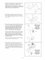
1. Identify the Front Stabilizer (3). While another person
lifts the front of the Frame (1), attach the Front
Stabilizer to the Frame with two M10 x 112mm
1
32
34
Carriage Bolts (34) and two M10 Nylon Locknuts (29).
Make sure that the Front Stabilizer is turned so the
Whee{s (32) are not touching the floor.
2. While another person lifts the back of the Frame (1),
attach the Rear Stabilizer (4) to the Frame with two
MI0 x 112mm Carriage Bolts (34) and two M10 Nylon
Locknuts (29).
2
1
3. While another person holds the Upright (2) in the position shown, connect the Upper Wire Harness (86) to
the Lower Wire Harness (87). Carefully pull the
upper end of the Upper Wire Harness to remove
any slack. While holding the upper end of the
Upper Wire Harness, insert the Upright into the
Frame (1). Do not pinch the Wire Harnesses.
91
Slide an M10 Split Washer (70) and a Frame Spacer
(83) onto an M10 x 88mm Button Bolt (63). Insert the
Button Bolt into the Frame (1) and the Upright (2).
Make sure that the concave end of the Frame
Make sure the
wire harnesses
do not get
pinched and
damaged during
this step.
793
Spacer is turned toward the Frame. Do not tighten
the Button Bolt yet.
Attach the Water Bottle Holder (91) to the Upright
(2) with two M4 x 22mm Screws (93).
4. While another person holds the Console (5) in the
position shown, connect the wire harness on the
Console to the Upper Wire Harness (86). Insert the
excess wire harness into the Upright (2). Next, attach
the Console to the Upright with four M4 x 16mm
Screws (66). Be careful to avoid p{nching the wire
harnesses.
4
Wire
Harness
/5
86
Make sure the
wire harnesses
do not get
pinched and
damaged during
this step.
66
66
i
6
i
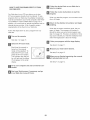
5. The Console (5) requires four "D" batteries (not includ=
ed); alkaline batteries are recommended. Pull the bat=
tery drawer open. Insert four batteries into the battery
drawer. Make sure that the batteries are oriented as
shown by the diagram inside the battery drawer.
Close the battery drawer. Note: When the batteries are
installed correctly, the fan will turn on for a moment.
Batteries
Battery
Drawer
6. Identify the Left Handlebar (9), which is marked with a
sticker. Insert the Left Handlebar into one of the
Handlebar Legs (79); make sure that the Handlebar
Leg is turned so the hexagonam homes are on the
indicated side. Attach the Left Handlebar to the
Handlebar Leg with two M8 x 45mm Button Bolts (50)
and two M8 Nylon Locknuts (46). Make sure that the
Nylon Locknuts are inside of the hexagonN holes.
Do not fully tighten the Button Bolts yet.
Apply a small amount of the included grease to the left
and right axles on the Upright (2).
Grease
\
J
53
26
25
22
Carefully slide an Upright Spacer (26), a Handlebar
Spacer (25), the Left Handlebar (9), and a Handlebar
Cap (23) onto the left axle on the Upright (2) as shown.
Slide an M10.3 Black Washer (53) onto an M8 x 19mm
Shoulder Screw (22), and tighten the Shoulder Screw
into the axJe.
_46
!
tgonN
Holes
/-79
Attach the Right Handlebar and the other Handlebar Leg
(not shown) in the same way.
7. Hold the lower end of the left Handlebar Leg (79) inside
of the left Front Flex Bracket (17). Apply a small
amount of grease to an MI0 x 78mm Button Bolt (27).
Attach the left Handlebar Leg to the left Front Flex
Bracket with the Button Bolt, two MI0 Washers (38),
and an MI0 Nylon Locknut (29). Bo not overtighten
the Nylon Locknut; the left Handlebar Leg must be
able to pivot free{y.
79
/
L
17
!
38
27
Attach the right Handlebar Leg (79) to the right Front
Flex Bracket (17) in the same way.
Refer to step 6. Tighten the M8 x 45mm Button Bolts
(50) in the Handlebar Legs (79). Refer to step 3.
Tighten the M10 x 88mm Button Bolt (63).
Grease
\
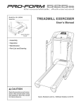
8. identify the Left Pedal (13). Attach the Left Pedal to the
left Flex Bar (14) with an MI0 x 33mm Carriage Bolt
(20), an M10 Washer (38), and a Pedal Knob (15) as
shown. Note: The Left Pedal can be attached in any of
five positions (see HOW TO ADJUST THE PEDALS on
page 9).
Attach the Right Pedal (not shown) in the same way.
Make sure that both Pedals are in the same position.
14
15
9. Make sure that all parts of the elliptical crosstrainer are properly tightened. Note: Some hardware may
be left over after assembly is completed. To protect the floor or carpet from damage, place a mat under the
elliptical crosstrainer.
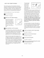
HOW TO USE THE ELUPTICAL
HOW TO ADJUST THE PEDALS
The motion of the
pedals is deter z
mined by their
positions on the
flex bars. There
Bolt
Flex Bar
are five positions.
To adjust each
pedal, first loosen
the knob beneath
Pedal
the pedal. Next,
Knob
push the bolt
upward, slide the
pedal forward or backward to the desired position, and
then retighten the knob. Make sure that both pedals
are in the same position.
HOW TO EXERCISE ON THE ELLiPTiCAL
CROSSTRAINER
To mount the elliptical crosstrainer, hold the handgrip
pulse sensor and step onto the pedal that is in the Iowz
est position. Then, step onto the other pedal. Push the
pedals until they begin to move with a continuous
motion. Note: The pedam disks can turn in either
direction, it is recommended that you move the
pedal disks in the direction shown by the arrow
below; however, for variety, you can turn the pedam
disks in the opposite direction.
Handgrip
Pulse Sensor
CROSSTRAtNER
To dismount the elliptical crosstrainer, wait until the
pedals come to a complete stop. Note: The elliptical
crosstrainer
does not have a free wheel; the pedals will continue to move until the flywheel stops.
When the pedals are stationary, step off the highest
pedal first. Then, step off the lowest pedal.
HOW TO USE THE HANDLEBARS
The handlebars are
designed to add
upper-body exercise to your workouts. Push and pull
the handlebars as
you exercise to
work your arms,
shoulders, and
back.
Handlebars
To exercise only
your lower body,
hold the handgrip
pulse sensor as
you exercise.
A CAUTION: Before
using
thee. pt cal crosstrainer,
tions ....
read the following
precau-
• Always hold the handgrip pulse sensor or the
handlebars when mounting, dismounting,
or
using the elliptical crosstrainer.
, When you stop exercising,
sJowly come to a stop.
Pedals
Handgrip
Pulse
Sensor
The pu_se sensor is
Various factors may
heart rate readings.
intended only as an
ing heart rate trends
allow the pedals to
not a medical device.
affect the accuracy of
The pulse sensor is
exercise aid in determinin general,
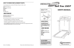
Button
f
.........................................
_
i, -,_
v
_ i
Stoat±Programs
VVeightLoss
Interval
WeightLoss
Plateau
\
1
3
4
Aerobic
Aerobic
Progressfve
Interval
5
6
Performanoe
PeCrormance
Progressive
Interval
I
DisplayButtons
On/Reset Button
Resistance Buttons
FEATURES OF THE CONSOLE
portable stereo, computer, or VCR and play special
iFIT.com CD and video programs (iFIT.com CDs and
videocassettes are available separately), iFF.com CD
and video programs automatically control the resistance of the pedals and prompt you to vary your pace
as a personal trainer coaches you through every step
of your workout. High-energy music provides added
motivation. To purchase iFIT.com CDs and videocassettes, call toll-free 1-800-735-0768.
The advanced console offers a selection of features
designed to make your workouts more enjoyable and
effective. When the manual mode of the console is
selected, the resistance of the pedals can be changed
with the touch of a button. As you pedal, the console
will provide continuous exercise feedback. You can
even measure your heart rate using the built-in handgrip pulse sensor.
in addition, the console offers six Smart programs. Each
program automatically changes the resistance of the
pedals and prompts you to increase or decrease your
pace as it guides you through an effective workout.
With the elJiptical crosstrainer connected to your computer, you can also go to our Web site at
www.iFF.com and access programs directly from the
internet. Explore www.iFIT.com for more information.
The console also features iFF.com interactive technology. Having iFF.com interactive technology is like having a personal trainer in your home. Using a stereo
audio cable (available at electronics stores), you can
connect the elliptical crosstrainer to your home stereo,
To use the manual mode of the console, see page
11. To use a Smart program, see page 13. To use
an iF_T.com CD or videocassette,
see page 17. To
use a program directly from our Web site, see page
18.
10
seconds, if you use the handgrip pulse sensor,
the display will also show your heart rate (see
step 5 on page 12).
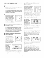
HOW TO USE THE MANUAL MODE
Turn on the consoJe.
To view only the distance
Upper Button
you have pedaled or the
number of calories or fat
calories you have burned,
press the upper button on
the left side of the large
display until only the word
DISTANCE, CALORIES, or
FAT CALORIES appears in the upper section of
the large display. Make sure that the word SCAN
does not appear. To again view the distance you
have pedaled and the numbers of calories and
fat calories you have burned, press the upper
button until the word SCAN reappears.
Note: The console requires four 1.5V "D" batteries
(see assembly step 5 on page 7).
To turn on the console, press the On/Reset button
or begin pedaling. (See the drawing on page 10 to
identify the On/Reset button.)
Select the manual mode.
Each time the console is
turned on, the manual
mode will be selected, if a
program has been selected, select the manual
mode by pressing the
Program button repeatedly until the letters RPM
appear in the small display.
Begin pedaling and change the resistance
the pedals as desired.
The center of
the _arge display
will show the
elapsed time and
your current pace
(pace is shown in
minutes per mile). The display will change from
one number to the other every few seconds.
Note: When a program is selected, the display
will show the time remaining in the program
instead of the elapsed time.
of
As you pedal, change the resistance of the ped=
ais by pressing the + and - buttons below the
large display. There are ten resistance levels-level 10 is the most challenging. Note: After the
buttons are pressed, it will take a few seconds for
the resistance to reach the selected setting.
To view only the elapsed time or your pace, press
the center button on the left side of the large display until only the word TIME or PACE appears.
Make sure that the word SCAN does not appear.
To view both the elapsed time and your pace,
press the center button until the word SCAN
reappears.
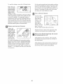
FoJtow your progress with the small display
and the large display.
The small display wHJ
show your pedaling pace,
in revolutions per minute
(RPM). The indicator bar
in the small display will
increase or decrease in
The lower section of the marge
display will show
your pedaling
speed and the
resistance level.
indicator Bar
length as you increase or
decrease your pedaling
pace.
The display will change from one number to the
other every few seconds.
The upper section of the
To view only your pedaling speed or the resistance level, press the lower button on the left
side of the large display until only the word
SPEED or RESISTANCE appears. Make sure
that the word SCAN does not appear. To view
both your pedaling speed and the resistance
level, press the lower button until the word SCAN
reappears.
large display
wiJJshow the
distance you
have pedaled
and the numbers of calories and fat ca[odes you
have burned (see FAT BURNING on page 20 for
an explanation of fat calories). The display will
change from one number to the next every few
11
To reset the displays, press the On/Reset button.
For the most accurate heart rate reading, continue
to hold the handgdps for about 30 seconds. Note:
When you first hold the handgrips, the large display will show your heart rate continuously for 30
seconds. The display will then show your heart
rate along with other feedback modes.
Note: The console can show
speed and dis=
',,SPEED
tance in either
miles or kilometers. The let=
ters MPH or KM/H will appear in the lower section
of the large display to show which system of mea=
surement is selected. To change the system of
measurement, hold down the On/Reset button for
about six seconds. Note: When the button is held
down, the fan will turn on for a moment. When the
batteries are replaced, it may be necessary to res=
elect the desired system of measurement.
Turn on the fan if desired.
To turn on the
fan at low speed,
press the fan
button. To turn
on the fan at
high speed,
Thumb
Wheel
press the fan
Button
button a second
time. To turn off
the fan, press the fan button a third time.
Measure your heart rate if desired.
if there are
thin sheets of
plastic on the
metam contacts
on the handgrips, peel off
Metal
Contacts
the plastic. To
use the handgrip pulse sensor, hold the handgrips with your palms resting
against the metal contacts. Avoid moving your
hands. When your pulse is detected, the heartshaped indicator in the large display will flash
each time your heart beats. After a moment, two
dashes (= =) will appear and then your heart rate
will be shown.
Rotate the thumb wheel on the right side of the
console to pivot the fan to the desired angle.
When you are finished exercising,
witl automatically
turn off.
the console
if the pedals are not moved for a few seconds,
the displays wiJJpause and the time will flash in
the large display.
If the pedals are not moved and the console but=
tons are not pressed for a few minutes, the con=
sole will turn off to conserve the batteries.
12
The target pace
for the current
period will be
shown by the
arrows in the
small display. To
pedal at the target
pace, simply
increase or decrease your pace until there is one
arrow pointing to each segment of the indicator
bar (see the drawing above). At the end of each
period, the number of arrows will change if a dif=
ferent target pace is programmed for the next
period. When the number of arrows changes,
change your pace until there is again one arrow
pointing to each segment of the indicator bar.
important: The target pace is intended only to
provide a goa!. Your actual pace may be slower than the target pace, especially during the
first few months of your exercise program.
Make sure to pedal at a pace that is comfortable for you.
HOW TO USE A SMART PROGRAM
Each Smart program will automatically change the
resistance of the pedals and prompt you to increase or
decrease your pace as it guides you through an effective workout. Programs 1 and 2 are weight Joss programs, programs 3 and 4 are aerobic programs, and
programs 5 and 6 are high-performance programs.
Follow the steps below to use a Smart program.
Turn on the console.
See step 1 on page 11.
Select one of the Smart programs.
Each time the console is
turned on, the manual
mode will be selected. To
select a Smart program,
press the Program button
repeatedly until the num=
ber 1, 2, 3, 4, 5, or 6
appears in the small dis=
play.
Begin pedaling
During the program, the center of the large dis=
play will show the time remaining in the program.
If you stop pedaling for a few seconds, the dis=
plays will pause and the time will flash. If you
continue pedaling after the program is completed,
the displays will continue to show exercise feedback.
to start the program.
To start the program, simply begin pedaling. Each
Smart program consists of 20 or 30 one-minute
periods. One resistance level and one target pace
are programmed for each period. (The same
resistance level and/or target pace may be programmed for two or more consecutive periods.)
Follow your progress with the large display.
See step 4 on page 11.
Measure your heart rate if desired.
See step 5 on page 12.
At the end of each period of the program, the
resistance of the pedals will automatically change
if a different resistance level is programmed for
the next period. Note: if the resistance level is too
high or too low, you can change it by pressing the
+ and = buttons below the large display. However,
when the current period is completed, the resistance of the pedals will automatically change if a
different resistance level is programmed for the
next period.
Turn on the fan if desired.
See step 6 on page 12.
When you are finished exercising,
witl automatically
turn off.
See step 7 on page 12.
13
the console
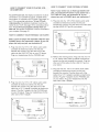
HOW TO CONNECT YOUR PORTABLE STEREO
HOW TO CONNECT
OR COMPUTER
YOUR CD PLAYER,
VCR,
To use iF_T.com CDs, the elliptical crosstrainer must be
connected to your portable CD player, portable stereo,
home stereo, or computer with CD player. See pages 14
and 15 for connecting instructions. To use iHT.com
videocassettes, the elliptical crosstrainer must be conz
nected to your VCR. See page 16 for connecting instrucz
tions. To use iF_T.com programs directly from our
Web site, the elliptical crosstrainer must be connected to
your computer. See page 15.
Note: if your stereo has an RCA-type AUDIO OUT
jack, see instruction A below, if your stereo has a
118" LiNE OUT jack, see instruction B. if your
stereo has only a PHONES jack, see instruction C.
A. Plug one end of a 1/8" to RCA stereo audio cable
(available at electronics stores) into the jack
beneath the console. Plug the other end of the cable
into the AUDIO OUT jack on your stereo.
C
HOW TO CONNECT YOUR PORTABLE CD PLAYER
AUDIOOUT
LI_EOUT
Note: If your CD player has separate LiNE OUT and
PHONES jacks, see instruct{on A below, if your CD
player has only one jack, see instruction B.
Cable
A. Plug one end of a 1/8" to 1/8" stereo audio cable
(available at electronics stores) into the jack
beneath the console. Plug the other end of the
cable into the LiNE OUT jack on your CD player.
Plug your headphones into the PHONES jack.
Audio
B.
C.
B. Plug one end of a 1/8" to 1/8" stereo audio cable
(available at electronics stores) into the jack
beneath the console. Plug the other end of the
cable into a 1/8" Y-adapter (available at electronics
stores). Plug the Y-adapter into the PHONES jack
on your CD player. Plug your headphones into the
other side of the Y-adapter.
14
__
Refer to the drawing above. Plug one end of a 1/8"
to 1/8" stereo audio cable (available at electronics
stores) into the jack beneath the console. Plug the
other end of the cable into the LINE OUT jack on
your stereo.
Plug one end of a 1/8" to 1/8" stereo audio cable
(available at electronics stores) into the jack
beneath the console. Plug the other end of the
cable into a 1/8" Y=adapter (available at electronics
stores). Plug the Y=adapter into the PHONES jack
on your stereo. Plug your headphones into the
other side of the Y=adapter.
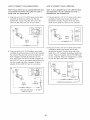
HOW TO CONNECT YOUR HOME STEREO
HOW TO CONNECT YOUR COMPUTER
Note: if your stereo has an unused LiNE OUT jack,
see instruction A below. Jf the LiNE OUT jack is
being used, see instruction B.
Note: if your computer has a 1/8" LINE OUT jack,
see instruction A. If your computer has only a
PHONES jack, see instruction B.
A. Plug one end of a 1/8" to RCA stereo audio cable
(available at electronics stores) into the jack
beneath the console. Plug the other end of the
cable into the LiNE OUT jack on your stereo.
A. Plug one end of a 1/8" to 1/8" stereo audio cable
(available at electronics stores) into the jack
beneath the console. Plug the other end of the
cable into the LiNE OUT jack on your computer.
A
.......
!!%
lu.....
u
........
Cable
Audio %_
l
B. Plug one end of a 1/8" to 1/8" stereo audio cable
(available at electronics stores) into the jack
beneath the console. Plug the other end of the
cable into a 1/8" Y-adapter (available at electronics
stores). Plug the Y-adapter into the PHONES jack
on your computer. Plug your headphones or speakers into the other side of the Y-adapter.
B. Plug one end of a 1/8" to RCA stereo audio cable
(available at electronics stores) into the jack beneath
the console. Plug the other end of the cable into an
RCA Y=adapter (available at electronics stores).
Next, remove the wire that is currently plugged into
the LiNE OUT jack on your stereo and plug the wire
into the unused side of the Y=adapter. Plug the Y=
adapter into the LiNE OUT jack on your stereo.
_® .......
Audio
Cable
__
n .........
Cable
Audio
RCA
Y-adapter
Wire removed from _E:_
LINE OUT jack
_
15
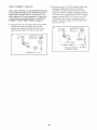
HOW TO CONNECT YOUR VCR
Note: Ifyour VCR has an unused AUDIO OUT jack,
see instruction
A below. IftheAUDIO OUT jack is
being used, see instruction B. If you have a TV
with a buHtqn VCR, see instructionB. if your VCR
is connected to your home stereo,see HOW TO
CONNECT YOUR HOME STEREO on page 15.
A. Plug one end of a 1/8" to RCA stereo audio cable
(available at electronics stores) into the jack
beneath the console. Plug the other end of the
cable into the AUDIO OUT jack on your VCR.
B. Plug one end of a 1/8" to RCA stereo audio cable
(available at electronics stores) into the jack
beneath the console. Plug the other end of the
cable into an RCA Yzadapter (available at electronics stores). Next, remove the wire that is currently
plugged into the AUDIO OUT jack on your VCR
and plug the wire into the unused side of the Yadapter. Plug the Y-adapter into the AUDIO OUT
jack on your VCR.
B
A
Audio
Cable
AUDIO OUT jack
16
The program will function in almost the same way
as a Smart program (see step 3 on page 13).
However, an electronic "chirping" sound will alert
you when the resistance level and/or the target
pace is about to change.
HOW TO USE IFIT.COM CD AND VIDEO
PROGRAMS
To use iFF.com CDs or videocassettes, the elliptical
crosstrainer must be connected to your portable CD
player, portable stereo, home stereo, computer with
CD player, or VCR. See HOW TO CONNECT YOUR
CD PLAYER, VCR, OR COMPUTER on page 14. To
purchase iFIT.com CDs and videocassettes,
call
toll-free 1-800-735-0768.
Note: If the resistance of the pedals and/or the
target pace does not change when a "chirp" is
heard:
Make sure that the indicator near the iFiT.com
button is lit.
, Adjust the volume of your CD player or VCR.
If the volume is too high or too low, the console may not detect the program signams.
Follow the steps below to use an iFF.com CD or
video program.
Turn on the console.
, Make sure that the audio cable is properly
connected and that it is fulty plugged in.
See step 1 on page 11.
Select the iF_T.com mode.
Follow your progress with the large display.
Each time the console is
turned on, the manual
mode will be selected. To
select the iFIT.com mode,
press the iFF.com button.
The indicator near the but=
See step 4 on page
11.
Measure your heart rate if desired.
See step 5 on page 12.
Turn on the fan if desired.
ton will light and the letters
iF will appear in the small
display.
See step 6 on page 12.
When you are finished exercising,
witl automatically turn off.
insert the iF_T.com CD or videocassette.
if you are using an iFIT.com CD, insert the CD
into your CD player, if you are using an iFIT.com
videocassette, insert the videocassette into your
VCR.
See step 7 on page 12.
Press the play button on your CD player or
VCR.
A moment after the play button is pressed, your
personal trainer will begin guiding you through
your workout. Simply follow your personal trainer's
instructions.
17
the console
Fol!ow the desired
HOW TO USE PROGRAMS
OUR WEB SiTE
DIRECTLY FROM
links on our Web site to
select a program.
Follow the on-line instructions
to start the
program.
Our Web site at www.iFF.com allows you to play
iFIT.com programs directly from the internet. To use
programs from our Web site, the elliptical crosstrainer
must be connected to your home computer. See HOW
TO CONNECT YOUR COMPUTER on page 16. In
addition, you must have an internet connection and an
internet service provider. A list of specific system
requirements will be found on our Web site.
When you start the program, an on-screen countdown will begin.
Return to the eIHptical crosstrainer
pedaling.
and begin
When the on-screen countdown ends, the program will begin. The program will function in
almost the same way as a Smart program (see
step 3 on page 13). However, an electronic "chirping" sound will alert you when the resistance level
and/or the target pace is about to change.
Follow the steps below to use a program from our
Web site.
Turn on the console.
See step 1 on page 11.
Follow your progress with the large display.
Select the iF_T.com mode.
See step 4 on page
11.
Each time the console is
turned on, the manual
mode will be selected. To
Measure your heart rate if desired.
select the iFF.com mode,
press the iFF.com button.
The indicator near the but-
See step 5 on page 12.
When you are finished exercising,
automatically turn off.
ton will light and the letters
iF will appear in the small
display
Go to your computer
nection.
See step 7 on page 12.
and start an internet con=
Start your Web browser, if necessary, and go
to our Web site at www.iFIT.com.
18
the console
MAINTENANCE
AND TROUBLESHOOTING
HANDGRIP PULSE SENSOR TROUBLESHOOTING
inspect and tighten all parts of the elliptical crosstrainer
regularly Replace any worn parts immediately
Avoid moving your hands while using the handgdp
pulse sensor. Excessive movement may interfere
with heart rate readings.
To clean the elliptical crosstrainer, use a damp cloth
and a small amount of mild soap. Important: To
avoid damage to the console, keep liquids away
from the console and keep the console out of
direct sunlight.
Do not hold the metal contacts too tightly; doing so
may interfere with heart rate readings.
BATTERY REPLACEMENT
For the most accurate heart rate reading, hold the
metal contacts for about 30 seconds.
if the console displays become dim, the batteries
should be replaced; most console problems are the
result of low batteries. Refer to assembly step 5 on
page 7 for replacement instructions.
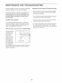
HOW TO LEVEL THE ELLIPTICAL
For optimal performance of the handgrip pulse sensor, keep the metal contacts clean. The contacts
can be cleaned with a soft cloth--never use alcohol,
abrasives, or chemicals.
CROSSTRAINER
After the elliptical
crosstrainer has
been moved to
the location
where it will be
used, make sure
that the ends of
both stabilizers
are touching the
floor, if the elliptical crosstrainer
Leveling Foot
rocks slightly during use, turn one or both of the leveling feet under the front stabilizer until the rocking
motion is eliminated.
19
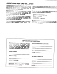
CONDITIONING
GUIDELINES
During the first few minutes of exercise, your body
uses easily accessible carbohydrate calories for energy. Only after the first few minutes of exercise does
your body begin to use stored fat calories for energy.
If your goal is to burn fat, adjust the intensity of your
exercise until your heart rate is near the lowest number in your training zone as you exercise.
_WARNING:
Before beginning this or any exercise pro=
gram, consult your physician. This is especially important for persons over the age of
35 or persons with pre-existing health problems.
For maximum fat burning, adjust the intensity of your
exercise until your heart rate is near the middle num=
bet in your training zone as you exercise.
o The pulse sensor is not a medical device.
Various factors may affect the accuracy of
heart rate readings. The pulse sensor is
intended only as an exercise aid in determining heart rate trends in general.
Aerobic
If your goal is to strengthen your cardiovascular sys=
tem, your exercise must be "aerobic." Aerobic exercise is activity that requires large amounts of oxygen
for prolonged periods of time. This increases the
demand on the heart to pump blood to the muscles,
and on the lungs to oxygenate the blood. For aerobic
exercise, adjust the intensity of your exercise until
your heart rate is near the highest number in your
training zone as you exercise.
The following guidelines will help you to plan your
exercise program. Remember that proper nutrition
and adequate rest are essential for successful results.
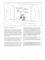
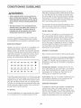
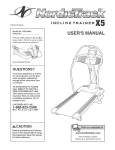
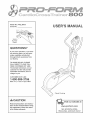
EXERCISE INTENSITY
Whether your goal is to burn fat or to strengthen your
cardiovascular system, the key to achieving the
desired results is to exercise with the proper intensity.
The proper intensity level can be found by using your
heart rate as a guide. The chart below shows recommended heart rates for fat burning, maximum fat
burning, and cardiovascular (aerobic) exercise.
165
155 145
140
130 125
I15
_
103
C_
145 138
i30
125
118 110
125
120
115
110
105
95
90
20
30
40
50
60
70
80
Exercise
WORKOUT
GUIDELINES
Each workout should include the following three parts:
A warm-up, consisting of 5 to 10 minutes of stretching
and light exercise (see SUGGESTED STRETCHES
on page 21 ). A proper warm=up increases your body
temperature, heart rate, and circulation in preparation
for exercise.
Training zone exercise, consisting of 20 to 30 minutes of exercising with your heart rate in your training
zone. Note: During the first few weeks of your exercise program, do not keep your heart rate in your
training zone for longer than 20 minutes.
To find the proper heart rate for you, first find your age
at the bottom of the chart (ages are rounded off to the
nearest ten years). Next, find the three numbers above
your age. The three numbers are your "training zone."
The lower two numbers are recommended heart rates
for fat burning; the highest number is the recommended heart rate for aerobic exercise.
A cool-down, with 5 to 10 minutes of stretching. This
will increase the flexibility of your muscles and will
help to prevent post=exercise problems.
EXERCISE FREQUENCY
To maintain or improve your condition, complete three
workouts each week, with at least one day of rest
between workouts. After a few months of regular exer=
cise, you may complete up to five workouts each week
if desired. The key to success is to make exercise a
regular and enjoyable part of your everyday life.
Fat Burning
To burn fat effectively, you must exercise at a relative=
ly low intensity level for a sustained period of time.
2O
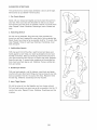
SUGGESTED
STRETCHES
The correct form for several basic stretches is shown at the right.
Move slowly as you stretch--never bounce.
1. Toe Touch Stretch
Stand with your knees bent slightly and slowly bend forward from
your hips. Allow your back and shoulders to relax as you reach
down toward your toes as far as possible. Hold for 15 counts, then
relax. Repeat 3 times. Stretches: Hamstrings, back of knees and
back.
2. Hamstr{ng
Stretch
Sit with one leg extended. Bring the sole of the opposite foot
toward you and rest it against the inner thigh of your extended leg.
Reach toward your toes as far as possible. Hold for 15 counts, then
relax. Repeat 3 times for each leg. Stretches: Hamstrings, lower
back and groin.
3. CamflAchHJes Stretch
With one leg in front of the other, reach forward and place your
hands against a wall. Keep your back leg straight and your back
foot flat on the floor. Bend your front leg, lean forward and move
your hips toward the wall. Hold for 15 counts, then relax. Repeat 3
times for each leg. To cause further stretching of the achilles tendons, bend your back leg as well. Stretches: Calves, achilles tendons and ankles.
4. Quadriceps
Stretch
With one hand against a wall for balance, reach back and grasp
one foot with your other hand. Bring your heel as close to your buttocks as possible. Hold for 15 counts, then relax. Repeat 3 times
for each leg. Stretches: Quadriceps and hip muscles.
5. Inner Thigh Stretch
Sit with the soles of your feet together and your knees outward.
Pull your feet toward your groin area as far as possible. Hold for 15
counts, then relax. Repeat 3 times. Stretches: Quadriceps and hip
muscles.
21
PART LiST--Model
Key No.
Qty.
1
1
2
3
4
No. PFEL39030
Description
RoG03A
Key No.
Qty.
Description
Frame
50
4
M8 x 45mm Button Bolt
1
1
1
Upright
Front Stabilizer
Rear Stabilizer
51
52
53
4
1
2
M6 x 18mm Bolt
"C" Magnet Bracket
MI 0.3 Black Washer
5
6
1
1
Console
Left Side Shield
54
55
1
1
"C" Magnet
Motor
7
8
9
1
2
1
Right Side Shield
Pedal Disc
Left Handlebar
56
57
58
1
2
12
Belt
M8 x 33mm Button Bolt
M6 Washer
10
11
12
13
14
15
16
17
18
19
20
21
22
23
24
25
26
27
28
29
30
31
32
33
34
35
36
1
2
1
1
2
2
1
2
4
12
2
4
2
2
4
2
2
2
4
6
1
1
2
2
4
2
1
Right Handlebar
Foam Grip
Right Pedal
Left Pedal
Flex Bar
Pedal Knob
Left Flex Bracket
Front Flex Bracket
Rear Flex Bushing
M6 x 33mm Flat Bolt
M10 x 33mm Carriage Bolt
Snap Ring
M8 x 19mm Shoulder Screw
Handlebar Cap
Handlebar Bushing
Handlebar Spacer
Upright Spacer
M10 x 78mm Button Bolt
Front Flex Bushing
M10 Nylon Locknut
Upright Bushing
Left Front Endcap
Wheel
M6 x 72mm Button Screw
MI0 x 112mm Carriage Bolt
Rear Stabilizer Endcap
Left Crank Arm
59
60
61
62
63
64
65
66
67
68
69
70
71
72
73
74
75
76
77
78
79
80
81
82
83
84
85
16
4
4
4
1
2
8
6
4
1
1
1
2
2
1
8
2
1
1
1
2
1
1
1
1
4
2
M6 Nylon Locknut
M6 Nut
M5 Nylon Locknut
M5 x 12mm Bolt
MI0 x 88mm Button Screw
M4 x 6mm SeGtapping Screw
M5 x 33mm Screw
M4 x 16mm Screw
M4 x 25mm Screw
Right Front Endcap
Reed Switch Clamp
MI0 Split Washer
Handlebar Endcap
Leveling Foot
M5 x 16mm Screw
M4 x 19mm Screw
M6 Eyebolt
Spring
Reed Switch
Reed Switch Bracket
Handlebar Leg
Side Shield Cover
"U" Bracket
Right Flex Bracket
Frame Spacer
M4 x 12mm Tap Screw
M5 Nut
37
38
39
40
41
42
43
44
45
46
47
48
49
1
6
1
2
1
2
1
1
4
7
2
1
1
Pulley
M I0 Washer
Crank
Crank Bearing
Flywheel
Flywheel Bearing
Magnet
Flywheel Axle
M8.5mm Washer
M8 Nylon Locknut
Crank Screw
Right Crank Arm
M6 x 25mm Bolt
86
87
88
89
90
91
92
93
94
#
#
#
1
1
2
2
4
1
4
2
1
2
1
1
Upper Wire Harness
Lower Wire Harness
Flex Bracket Spacer
M8 x 22mm Button Bolt
Motor Washer
Water Bottle Holder
M8 Nut
M4 x 22mm Screw
M6 Large Washer
Allen Wrench
Grease
User's Manual
Note: "#" indicates a non-illustrated part. Specifications are subject to change without notice. See the back cover
of this manual for information about ordering replacement parts.
22
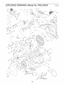
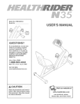
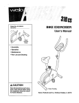
EXPLODED
DRAVVING--Model
71
11
71
No. PFEL39030
19,
RoGo3A
20-_
8O
19
21
66
\
26
Io
23
25
51
25
53 24
26
79
87
86
_79
!
67
62
68
65
74
38
27
31
48
32
35
81
44
78
8
""" if
46
47
.57
34
37
92
\/
JJ
15
65
14
18_
21_
59 _
23
HOW TO ORDER REPLACEMENT
PARTS
To order replacement parts, simply call our Customer Service Department toll-free at 1-800o999-3756, Monday
through Friday, 6 a.m. until 6 p.m. Mountain Time (excluding holidays). To help us assist you, please be
prepared to give the following information when calling:
• The MODEL NUMBER of the product (PFEL39030)
• The NAME of the product (PROFORM _"800 CARDIO CROSSTRAINER)
• The SERIAL NUMBER of the product (see the front cover of this manual)
• The KEY NUMBER and DESCRiPTiON
of the part(s) (see page 22)
LIMITED WARRANTY
iCON Health & Fitness, Inc. (ICON), warrants this product to be free from defects in workmanship and
material, under normal use and service conditions, for a period of ninety (90) days from the date of purchase. This warranty extends only to the original purchaser, iCON's obligation under this warranty is limited to replacing or repairing, at ICON's option, the product through one of its authorized service centers.
All repairs for which warranty claims are made must be pre-authorized by iCON. This warranty does not
extend to any product or damage to a product caused by or attributable to freight damage, abuse, misuse, improper or abnormal usage or repairs not provided by an ICON authorized service center; products
used for commercial or rental purposes; or products used as store display models. No other warranty
beyond that specifically set forth above is authorized by ICON.
iCON is not responsible or liable for indirect, special or consequential damages arising out of or in connection with the use or performance of the product or damages with respect to any economic loss, loss
of property, loss of revenues or profits, loss of enjoyment or use, costs of removal or installation or other
consequential damages of whatsoever nature. Some states do not allow the exclusion or limitation of incidental or consequential damages. Accordingly, the above limitation may not apply to you.
The warranty extended hereunder is in lieu of any and all other warranties and any implied warranties of
merchantability or fitness for a particular purpose is limited in its scope and duration to the terms set forth
herein. Some states do not allow limitations on how long an implied warranty lasts. Accordingly, the above
limitation may not apply to you.
This warranty gives you specific legal rights. You may also have other rights which vary from state to state.
iCON HEALTH & FITNESS, INC., 1800 S. 1000 W., LOGAN, UT 84321-9813
Part No. 197639 R0603A
Printed in China © 2003 ICON Health & Fitness, Inc.