1
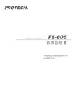
STEREO RE CEIVER AMPLIFIER
VC R
AUX
PO WE R
CD
DVD
TUNER
A
1
2
B
3
4
C
8
ME MO RY
BALANCE
MU TE
AU TO
VOL
SCAN
BASS
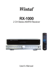
User Manual/Manual de Uso
6
7
AM /F M
TREBLE
AM 105
5
D
SLEEP
IMPORTANT SAFETY INSTRUCTIONS
NOTICE! !
Thank you for purchasing our product.
To assure the finest performance, please read this manual
carefully.Keep it in a safe place for future reference.
CAUTION
RISK OF SHOCK
CAUTION: To reduce the risk of electric shock, do
not remove cover (or back). No user-serviceable
parts inside. Only refer servicing to qualified service
personnel.
1. Read Instructions - All the safety and operating instructions should be read before the appliance is operated.
2. Retain Instructions - The safety and operating instructions should be retained for future reference.
3. Heed Warnings - All warnings on the appliance and in
the operating instructions should be adhered to.
4. Follow Instructions - All operating and use instructions
should be followed.
5. Do not use this apparatus near water.
6. Clean only with dry cloth.
7. Do not block any ventilation openings. Install in accordance with the manufacturer's instructions.
Explanation of Graphical Symbols
The lightning flash & arrowhead symbol,
within an equilateral triangle, is intended
to alert you to the presence of danger.
The exclamation point within an equilateral triangle is intended to alert you to the
presence of important operating and servicing instructions.
8. Do not near any heat sources such as radiators, heat
registers, stoves, or other apparatus (including amplifiers)
that produce heat.
9. Do not defeat the safety purpose of the polarized or grounding-type plug. A polarized plug has two blades with one
wider than the other. A grounding type plug has two blades
and a third grounding prong. The wide blade or the third
prong is provided for your safety. If the provided plug does
not fit into your outlet. Consult an electrician for replacement of the obsolete outlet.
10. Protect the power cord from being walked on or pinched.
WARNING
To reduce the risk of fire or electric shock, do not
expose this unit to rain or moisture.
11. Only use attachments/accessories specified by the
manufacturer.
12. Use only with the cart, stand, tripod,
bracket, or table specified by the manufacturer, or sold with the apparatus.
When a cart is used, use caution when
moving the cart/apparatus combination
to avoid injury from tip-over.
Voltage:
Voltages are 230V AC,50Hz.
This symbol on the product or on its packaging indicates that this product
shall not be trated as household waste. Instead it shall be handed over to
the applicable collection point for the recycling of electrical an electronic
equipment. By ensuring this product is disposed of correctly, you will help
prevent potential negative consequences for the environment and human
health, which could otherwise be caused by inappropriate waste handling
of this product. The recycling of amterials will help to conserve natural
resources. For more detailed information sabout recycling of this product,
please contact your local city office, your household waste disposal service
or the shop where you purchased the product.
13.Unplug this apparatus during lightning storms or when
unused for long periods of time.
14.Refer all servicing to qualified service personnel. Servicing is required when the apparatus has been damaged in
any way, such as power-supply cord or plug damage, liquid
has been spilled or objects have fallen into the apparatus,
the apparatus has been exposed to rain or moisture, or the
apparatus does not operate normally or has been dropped.
IMPORTANT SAFETY INSTRUCTIONS
15. Cleaning - Unplug this unit from the wall outlet before
cleaning. Do not use liquid cleaners or aerosol cleaners.
Use a damp cloth for cleaning.
16. Power lines - An outdoor antenna should be located
away from power lines.
17. Object and Liquid Entry - Care should be taken so that
objects do not fall and liquids are not spilled into the enclosure through openings.
3.Do not use your receiver immediately after transferring it from
a cold place to a warm due to there is risk of condensation.
4.Do not expose your receiver to water or excessively high temperatures.
5.After having disconnected your receiver, clean the case with
a soft cloth, or with a slightly damp leather chamois. Never use
strong solvents.
Note:
To CATV system installer's (U.S.
A.): This reminder is
provided to call the CATV system installer's
attention
to Article 820-40 of the NEC that provides guidelines
for proper grounding and, in particular , specifies that
the cable ground shall be connected as close to the
point of cable entry as practical.
PROTECT YOUR RECEIVER FROM
OVERHEATING
1.Do not block ventilation holes. Arrange the receiver so that air
can circulate freely.
2.Do not stack the receiver and other components directly on
top of each other.
SETUP AND MAINTENANCE OF
THE RECEIVER
3.Allow adequate ventilation when placing your receiver in a
stand.
4.Place an amplifier near the top shelf of the stand so heated
air rising from it will not affect other apparatus. If you have a
satellite receiver, you should place it on the top shelf.
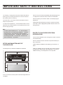
1.Provide spaces for sufficient ventilation as indicated:
15cm/6"
ST ER EO R EC EI VE R AMP LI FI ER
10cm/
4"
10cm/
4"
15cm / 6"
10cm/
4"
2.Do not connect to the AC power cords until all apparatus are
completed.
TABLES OF CONTENTS
TABLES OF CONTENTS
1
FIRST STEPS
2
UNPACK THE RECEIVER
2
ABOUT REMOTE CONTROL
3
BASIC CONNECTIONS
4
CONNECTING THE SPEAKERS
5
CONNECTING THE WIRES
5
CONNECTING THE MAIN SPEAKERS
5
CONNECTING THE ANTENNAS
5
CONNECTING FOR POWER
6
USING HEADPHONES
6
RECEIVER CONTROLS
& OPERATIONS
7
7
PANEL INTRODUCTION
DISPLAY MESSAGES
TUNING THE RECEIVER
8
8
8
8
8
9
9
9
9
SELECT THE AM/FM BAND
MANUAL TUNING
AUTO TUNING
STORING STATIONS IN MEMORY
TO STORE STATION
MANUAL PRESET
RETRIEVING PRESET STATIONS
CONNECTING AUXILIARY COMPONENTS
10
BACK PANEL INTRODUCTION
10
BEFORE YOU CONNECT
11
CONNECTING A COMPACT DISC PLAYER
11
REMOTE CONTROL
12
CARE AND MAINTENANCE
13
13
TROUBLESHOOTING TIPS
13
13
13
13
RECEIVER/TUNER OPERATION
REMOTE CONTROL OPERATION
GENERAL
CLEANING THE EXTERIOR
EQUIPMENT SPECIFICATIONS
14
1
FIRST STEPS
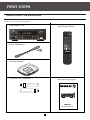
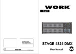
UNPACKING THE RECEIVER
You should receiver the following items:
One receiver unit
One Remote Control
ST ER EO R EC EI VE R AM PL IFI ER
Indoor FM antenna
VCR
AUX
POWER
CD
DVD
TUNER
A
1
2
B
3
4
C
5
6
D
7
8
SLEEP
AM/FM
MEMORY
BALANCE
MUTE
AUTO
VOL
SCAN
BASS
TREBLE
AM-105
AM loop antenna
AAA,R3,UM-4 batteries
One instruction book
VCR
CD
A
B
STER EO REC EIVE R AMPLI FIER
C
User Manual/Manual de Uso
2
1
3
5
POWER
TUNER
2
4
6
7
8
AM/FM
MEMORY
BASS
TREBLE
AM 105
AUX
DVD
D
SLEEP
BALANCE
MUTE
AUTO
VOL
SCAN
FIRST STEPS
ABOUT REMOTE CONTROL
INSTALLING BATTERIES IN THE
REMOTE CONTROL
REMOTE CONTROL OPERATION RANGE
Since the remote controller will be used for many of this
unit control operations, you should begin by installing the
supplied batteries.
1.Turn the remote controller over and slide the battery
compartment cover in the direction of the arrow.
ST ER EO R EC EI VE R AM PL IF IE R
2. Insert the batteries(AAA,R03,UM-4 TYPE) according to
the polarity markings on the inside of the battery compartment.
3.Close the battery compartment cover.
Within approximately
6m(19.7feet)
30
30
CAUTION
Danger of explosion if battery is incorrectly
replaced.
VCR
AUX
POWER
CD
DVD
TUNER
A
1
B
3
4
C
5
6
2
D
7
8
SLEEP
AM/FM
MEMORY
BALANCE
MUTE
AUTO
VOL
SCAN
BASS
TREBLE
NOTES ABOUT THE REMOTE CONTROL
AM-105
Batteries Replacement
If you find that the remote controller must be used close to the
main unit, the batteries are weak. Replace both batteries with
new ones.
NOTES:
NOTES:
1.Use AAA,R03,UM-4 batteries.
1.The area between the remote controller and the main unit must be
clear of large obstacles.
2.Be sure the polarities are correct.(See the illustration inside the battery compartment.)
2.Do not expose the remote control sensor to strong lighting, in
particular an inverter type fluorescent lamp. Otherwise, the remote
controller may not work properly. If necessary, position the main unit
away from direct lighting.
3.Remove the batteries if the remote controller is not used for an extended period of time. If batteries leak, dispose of them immediately.
4.Avoid touching the leaked material and contact with clothing, etc.
Clean the battery compartment thoroughly before installing new batteries.
3
FIRST STEPS
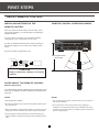
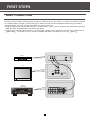
BASIC CONNECTIONS
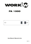
Assuming you have a DVD, the following steps will help you quickly set up your new receiver. If you have more electronic components, consult the table of contents or index for the page on which to find the connection description that best suits your situation.
the wires(bought from store ) and jacks have been color-coded to assist you.
1.Using an audio wire with red and white connectors, connect the audio OUT jack on the back of your stereo DVD to the audio
IN jack under the DVD heading on the back of the receiver.
2.Using the video cable with yellow connectors, connect the video OUT jack on the back of your DVD to the VIDEO IN or
VIDEO INPUT on the back of your TV. If there are multiple video jacks on the back of your TV, use VIDEO 1 .
DVD
IN FROM ANT
IN
Ch3
Ch4
OUT
199
VIDEO R
OUT TO TV
L
VIDEO
INPUT
TV
RIGHT
OUT AUDIO
S-VIDEO
L/
MONO
AUDIO
RECEIVER
ST ER EO RE CE IV ER AMP LI FI ER
4
IN
CABLE/
ANTENNA
FIRST STEPS
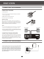
CONNECTING THE SPEAKERS
CONNECTING THE WIRES
1.Loosen the knob.
2.Insert the bare wire.[Remove approx.5mm(1/4
from the speaker wires].
) insulation
3.Tighten the knob and secure the wire.
Method 1
Or you also may use a banana plug.
Speaker Polarity
When connecting the speakers, make sure the polarities ("+"
speaker wire to "+" on the receiver) of speaker wires and terminals are matched. If the cords are reversed, the sound will be
distorted and will lack bass("out of phase"effect).
Method 2
NOTE:
1.Do not let the bare speaker wires touch each other or any metal part
of this unit. This could damage this unit or the speakers, or both.
RIGHT SPEAKER
2.Connect the speakers terminals to your speakers with the wire of the
proper gauge (keep as short as possible).if the connections are faulty,
no sound will be heard from the speakers.
RIGHT
CONNECTING THE MAIN SPEAKERS
The two main speakers should be set between six and 10 feet
apart. Putting the speakers any closer or any farther apart may
result in distorted sound. The speakers should also form a 45
degree angle to the central listening point in the room, creating
a triangle of listening enjoyment.
CONNECTING THE ANTENNAS
The AM and FM antennas connect to the AM and FM terminals
on the system's back panel. They must be hooked up for you
to receive clear reception. Uncoil the antenna wires and locate
the bare ends. Press down on the tab to open the terminal and
insert the wire. Snap the tab closed. After connecting the antennas, extend them to their full length and adjust their positioning for better reception.
5
LEFT SPEAKER
LEFT
FIRST STEPS
CONNECTING FOR POWER
Make sure you connect all your other electronic components
and the speakers before plugging your receiver into the outlet.
Plug the power cord into the wall outlet, matching the wide
blade of the plug with the wide slot in the outlet. Be sure to
insert the plug completely.
USING HEADPHONES
To listen privately through your audio system, use the HEADPHONES jack on the receiver. However, make sure you turn down the
volume before you put on the headphones. Increase the volume to the desired level after headphones are in place.
Hearing Comfort & Well-Being
1.Do not play your headset at a high volume.
hearing experts advise against continuous
extended play.
2.If you experience a ringing in your ears,
reduce volume or discontinue use.
6
RECEIVER CONTROLS & OPERATIONS
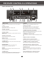
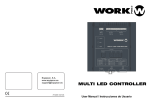
PANEL INTRODUCTION
1
3
2
4
6
5
STEREO RE CEIVER AMPLIFIER
7
8
9
10
11
12
13
14
15
16
17
18
19
20
1.INPUT selector
11. A/B/C/D
Turn the knob to select the input source you want to listen to
or watch.
Selects one of the 4 preset station groups (A to D).
12.Tuning scan button
2.Standby indicator
Press the SCAN+ side to tune to a higher Frequency.
Press the SCAN- side to tune to a lower frequency.
Press and keep two second minutes, scan automatically.
Lights up when this unit is in standby mode.
3.Number 1-8 button
Press these buttons to select preset tuning channel.
13.TUNER automatically tuning button
4.Display window
Hold down this button for more than 3 seconds to start automatically preset tuning(AM/FM is detached).
Display a variety of information. (e.g. Main volume source and
parameter etc.)
14.FM/AM band switches button
5.Remote control sensor
Press the button to switch the reception band between FM and
AM.
Receives signals from the remote controller.
15.Stores a station in the memory
6Master
volume
.
Controls the output level of all audio channels.
16.BASS Parameter adjustment buttons
Press the buttons to adjust the low-frequency response.
7.POWER switch
Press this switch to turn on the power. Press the switch again
to turn off the power.
17.TREBLE Parameter adjustment buttons
Press the buttons to adjust the high-frequency response.
8.Standby button
18.BALANCE Parameter adjustment buttons
Press this button to set this in the standby mode.
Press again turn on the power of this unit.
Press the buttons to adjust the balance between left and right.
9.MUTE
Allows you enjoyment for private listening with headphones.
When you connect headphones, no signals are output to all
speakers.
19.Headphone jack
Mute the sound. Press again to restore the audio out to the
previous volume level.
10.SLEEP button
20.Display(VFD)brightness adjustment buttons
Press the button repeatedly to turn the sleep time on and off,
and set the sleep time(10-20-30-40-50-60-70-80-90mins).
Press them to adjust brightness of the display(VFD).
7
RECEIVER CONTROLS & OPERATIONS
DISPLAY MESSAGES
The following is an example of all the display messages you may encounter while using your receiver. Specific messages re referenced within the section(s) they apply.
STEREO TUNED
L
R
SLEEP
MEMORY
KH z
MH z
SLEEP
STEREO
Tuner stereo signal detected.
Unit in Sleep mode
KHz
MHz
TUNED
Tuner station detected.
Tuner frequency unit
TUNING THE RECEIVER
SELECT THE AM/FM BAND
AUTO TUNING
1.Push the FM/AM button on the front panel (or the AM/FM
button on the remote) to activate the tuner.
Use the AUTO feature to automatically search for stations of
sufficient strength.
Press and hold AUTO button for 3 seconds on the remote.
Radio frequencies will be browsed and radio station stored
automatically. When all available radio stations are stored or if
all 32 memory locations are full, the auto preset will stop.
2.When using the remote you must press the AM/FM button
on the remote again to select the FM or AM band.
MANUAL TUNING
NOTE:
Press the SCAN + button on your remote button to move up
the AM or FM band. Press the SCAN - arrow button on your
remote to move down the AM or FM band. You may press and
hold SCAN + or SCAN- buttons 3 seconds to automatically
find next station.
Weak signal can affect the "Automatic Preset Storing Function" efficiency. Adjust the antenna for the best reception for more efficient search.
NOTES:
1.If there is interference, modify the location of the antenna until the
optimal sound is heard. TV and other electronic devices could be the
cause of interferences so try to position the antenna away of them.
2.Weak signal can affect the "auto Search function".Adjust the antenna
for better reception for more efficient search.
8
RECEIVER CONTROLS & OPERATIONS
STORING STATIONS IN MEMORY
RETRIEVING PRESET STATIONS
You can store up to 32 AM and FM stations, these stations can
be stored in random order.
1.Turn the INPUT knob on the front panel or press TUNER
button on the remote control to select TUNER as the input
source.
TO STORE A STATION
2.Press A/B/C/D button on the panel or the remote control to
s elect the group of preset stations that you are desire.
1.Press the FM/AM button on the front panel or remote control
to select the reception band.
3.Press number (1-8) buttons on the remote control to select
the number of preset stations that you are desire . Station
selected is displayed on the front panel display.
2.Select the station you want to store in memory using the methods described above.
3.Press the MEMORY button on the remote, "MEMORY" blinks
in the display. While "MEMORY" is blinking, press number
buttons on the remote for the station.
4.In the same way, You can select other stations stored.
If the Memory indicator on the display
turns off before you preset your station
selection, press MEMORY again.
MANUAL PRESET
1. Select the band wave by pressing FM/AM repeatedly.
2. Tune to a radio station (see "Manual tuning" on page 8
above for details).
3.Select a group (A - D) of preset stations. this group will be
displayed on the front panel display. For example: "A".
4. Press MEMORY button on the remote control."MEMORY"
appears on the display.
5.While the word "MEMORY" is still on, input your desired
preset number (1-8) buttons on the remote control to select
a preset radio station number. For example this number is
"1"."MEM OK" appears on the display. This station has been
stored to "A1".
6.Repeat steps 1 to 5 to store other stations.
NOTE:
1.A new setting can be programmed in place of the former one.
2.This memory is forever before reset.
9
CONNECTING AUXILIARY COMPONENTS
BACK PANEL INTRODUCTION
1
2
3
4
5 6 7 8 9 10 11
12
9.REC audio output jacks
1.FM antenna input
NOTE:
2.AM antenna input
The level is controlled by master volume.
3.Right channel speaker output
10.Pre out jacks
4.Left channel speaker output
NOTE:
A short plug is used between 10 and 11 jacks.
5.VCR audio input jacks
11.Amplifier input jacks
6.AUX audio input jacks
NOTE:
7.CD audio input jacks
A short plug is used between 10 and 11 jacks.
8.DVD audio input jacks
12.AC 230V/50Hz power input plug
10
CONNECTING AUXILIARY COMPONENTS
BEFORE YOU CONNECT.....
CONNECTING THE CABLES
POSITION CABLES CORRECTLY TO AVOID
- Protect components from power surges.
AUDIO HUM OR INTERFERENCE
- Connect all components before plugging power cords into the
- Insert all cable plugs firmly into their jacks.
wall outlet.
- Place audio/video cables to the sides of the receiver's back
- Always turn off the receiver and/or components before you
panel instead of straight down the middle after you connect
connect or disconnect any cables.
the components.
- Always make sure the color-coded plugs match the color of
- Try not to coil any power cables and keep them away from
the terminals in which they are inserted.
the audio/video cables as much as possible.
- The connection cable plugs and jacks are color-coded as
- Make sure all antennas and cables are properly grounded.
follows:
Refer to the Safety Tips sheet packed with your receiver.
Speaker Terminals: Red for positive (+) terminals. Black for
negative (-) terminals.
- Some units may be supplied with connection plugs that are
color-coded red and black instead of red and white. In this
case, the black plug takes the place of the white plug.
CONNECTING A COMPACT DISC PLAYER
Using one paired (red/white) stereo cable, connect your new
receiver to your compact disc player as shown to the right.
To play a CD, press CD, put the receiver in CD mode and
press PLAY.
CD
PLAYER
L
199
NOTE:
The AUDIO SOURCE connection can be used as input for any stereo
audio signal.
AUDIO
RECEIVER
STER EO REC EIVE R AMPLI FIER
11
R
CONNECTING AUXILIARY COMPONENTS
REMOTE CONTROL
1. Input selector buttons
Press these buttons to select an input source.
2.A/B/C/D button
Press the buttons to select a group of preset stations.
3.SLEEP button
VCR
AUX
POWER
CD
DVD
TUNER
A
1
2
B
3
4
C
5
6
9
Press the button repeatedly to turn the sleep timer on and off,
and set the sleep time(10-20-30-40-50-60-70-80-90mins).
1
4.BALANCE Parameter selector button
Press the button to select balance parameter. then press the
"8" button to adjust the balance between left and right.
10
2
5.MUTE
Mute the sound. Press again to restore the audio out to the
previous volume level.
D
7
8
SLEEP
AM/FM
MEMORY
BALANCE
MUTE
AUTO
3
11
4
6.BASS Parameter selector button
VOL
5
12
13
SCAN
BASS
6
Press the button to select bass tone, then press the "8" button
to adjust the low-frequency response.
TREBLE
14
7
8
7.TREBLE Parameter selector button
Press the button to select treble tone, then press the "8" button to adjust the high-frequency response.
8.PARAMETER selected and MASTER VOLUME
adjustment buttons
To adjust parameter selected or main volume.
9.Power button
Press this button to set this in the standby mode. Press again
turn on the power of this unit.
10.Number 1-8 button
Press the button to call preset station number.
11.MEMORY button
Use the button to enter a station to memory.
12.FM/AM band switches button
Press the button to switch the reception band between FM and
AM.
14.TUNING SCAN+,SCAN- buttons
13.TUNER automatic tuning button
Press the SCAN+ side to tune in to a higher frequency.
Press the SCAN- side to tune in to a lower frequency.
Press and keep two second minutes, scan automatically.
Press and hold the button 3 seconds, all stations are browsed
and stored automatically.(AM/FM is detached)
12
CARE AND MAINTENANCE
TROUBLESHOOTING TIPS
REMOTE CONTROL OPERATION
RECEIVER/TUNER OPERATION
STEREO indicator is off.
-
The remote control does not operate the unit.
- Another function is selected on the remote. Press the correct
function button.
- No batteries installed. Install the batteries before attempting
to operate the remote.
- The batteries are exhausted. Replace all batteries.
- The remote is not pointed at the remote control sensor on the
main unit or there is an obstacle between the remote and the
main unit.
-The remote control is too far from the main unit. Move closer.
Adjust the antenna.
The signal is too weak. Connect an external antenna.
The signal is Mono.
Sever hum or noise.
The signal is too weak. Connect an external antenna.
GENERAL
No audio.
NOTE:
Make sure the MUTE indicator on the front panel is off.
Make sure the speakers are turned on.
Check the connections.
Check the short plug between PRE OUT jacks and AMP IN
on the rear panel is inserted.
- Check the power cord connection.
-
Be sure to match the + and - ends of each battery to the symbols
shown in the remote battery compartment.
No audio from one channel.
- Check the speaker wire connection or connecting cable.
- Check the connection between the receiver and the speaker.
Noise when the TV is turned on.
- The TV too close to the unit.
CLEANING THE EXTERIOR
CLEANING THE EXTERIOR
- Disconnect the system from AC power before cleaning the
exterior of the system with a soft dust cloth.
13
EQUIPMENT SPECIFICATIONS
AMPLIFIER SECTION
Left & Right Channel......................................................................................................2X100Watts
Signal to Noise(A weight)..........................................................................................................85dB
Frequency Response......................................................................................20Hz-20 KHz+/-1.5 dB
AM TUNER SECTION
Frequency Response........................................................................................80Hz 2.3 KHz +/- 6dB
Usable Sensitivity........................................................................................... ....55dBu @ S/N 20 dB
Signal to Noise........................................................................................................................38 dB
Image Ratio......................................................................................................... 30 dB @ 1000KHz
IF Rejection ...........................................................................................................................40 dB
FM TUNER SECTION
Frequency Response......................................................................................... 40Hz-15 KHz+/- 3dB
Quieting................................................................................................................................24 dBu
Signal to Noise....................................................................................... 60 dB (stereo)/65 dB (mono)
Image Ratio..............................................................................................................................40dB
IF Rejection............................................................................................................................. 65dB
Specifications and features are subject to change without notice.
14
ESPAÑOL
RECEPTOR AM/FM
Y AMPLIFICADOR 2 x 100 W
STEREO RE CEIVER AMPLIFIER
VC R
AUX
PO WE R
CD
DVD
TUNER
A
1
B
3
4
C
5
6
2
D
7
8
SLEEP
AM /F M
ME MO RY
BALANCE
MU TE
AU TO
VO L
SC AN
BASS
TREBLE
AM 105
Manual de Uso
INSTRUCCIONES DE SEGURIDAD IMPORTANTES
1. Lea las instrucciones - Todas las instrucciones de seguridad
y funcionamiento debe ser leídas antes de usar la unidad.
ATENCION! !
Gracias por la adquisición de este producto.
Para asegurar un funcionamiento eficaz de la unidad, por
favor lea este manual cuidadosamente. Conservelo para
futuras referencias
CAUTION
RISK OF SHOCK
CAUTION: To reduce the risk of electric shock, do
not remove cover (or back). No user-serviceable
parts inside. Only refer servicing to qualified service
personnel.
2. Conserve las instrucciones - Las instrucciones de seguridad
y manejo deben ser guardadas para futuras referencias.
3. Tenga presente los avisos - Todos los avisos y advertencias
de la unidad deben ser tenidos en cuenta.
4. Sigua las instrucciones - Todas las instrucciones de uso
deben ser seguidas.
5. No use la unidad cerca del agua
6. Limpie la unidad sólo con un paño seco
7. No bloquee las tomas de ventilación, instale la unidad de
acuerdo a la instrucciones del fabricante
8. No coloque la unidad cerca de fuentes de calor como
radiadores, estufas u otros elementos (incluyendo
amplificadores) que generen calor.
Explicación de los símbolos gráficos
El rayo o una flecha dentro de un triángulo
equilátero le alerta de la presencia de
un peligro.
La exclamación dentro de un triángulo
equilátero, le alerta de la presencia de una
importante instrucción de manejo o
de seguridad.
9. No elimine la toma de tierra en la clavija de red. Una
toma de este tipo dispone de dos bornes y de fase y neutro
y una toma de tierra para seguridad. Si la toma mural no
dispone de este elemento, contacte con un electricista
10. Proteja el cable de red de pisadas o pinzamientos
11. Use únicamente accesorios o repuestos especificados
por el fabricante.
12. Use sólo es soporte, tabla o
trípode especificado por el fabricante
Cuando utilice un soporte, asegúrese
de utilizarlo con precaución a la
hora de moverlo para evitar daños
AVISO
Para reducir el riesgo de descargas eléctricas, no
exponga la unidad a la lluvia o humedad.
13. Desconecte la unidad durante tormentas eléctricas o
cuando no vaya a ser usado durante largo tiempo.
14. Diríjase a personal técnico especializado. Este servicio
será requerido cuando la unidad se haya dañado, por ejemplo
cable de res dañado, haya entrada líquido u otros objetos en
la unidad, haya sido expuesta a la lluvia o humedad o la unidad
no opere de manera adecuada.
Alimentación:
La alimentación está marcada en 230V AC,50Hz.
Este símbolo en su equipo o embalaje, indica que el presente producto
no puede ser tratado como residuos domésticos normales, sino que deben
entregarse en el correspondiente punto de recogida de equipos electrónicos
y eléctricos. Asegurándose de que este producto es desechado
correctamente, Ud. está ayudando a prevenir las consecuencias negativas
para el medio ambiente y la salud humana que podrían derivarse de la
incorrecta manipulación de este producto. EL reciclaje de materiales
ayuda a conservar las reservas naturales. Para recibir más información,
sobre el reciclaje de este producto, contacte con su ayuntamiento, su
punto de recogida más cercano o el distribuidor donde adquirió el producto.
INSTRUCCIONES DE SEGURIDAD IMPORTANTES
15. Limpieza - Desconecte la unidad de la toma mural antes
de limpiarla. No use líquidos limpiadores como aerosoles. Use
un paño húmedo para su limpieza.
3. No utilice la unidad inmediatamente después de pasar la
unidad de un sitio frío a otro templado debido a riesgo de
condensación interna.
16- Lineas de tensión - La antena exterior debe ser colocada
lejos de los cables de alta tensión.
4. No exponga el receptor al agua o temperaturas
excesivamente altas.
17. Entrada de líquidos u objetos - Tenga cuidado con la
entrada de líquidos u objetos en la unidad a través de las
aberturas de ventilación
5. Después de desconectar el receptor, limpie la carcasa
con un paño suave o ligeramente humedecido. No use
disolventes fuertes.
Nota:
Para instaladores de CATV (U.S.A.) deben prestar atención
al artículo 820-40 de el NEC que da las lineas maestras
para una adecuada conexión a tierra, en especial las
especificaciones de que cable debe ser conectado lo más
cerca posible del punto de entrada.
PROTEJA SU RECEPTOR DE LA
SOBRETEMPERATURA
1. No bloquee las tomas de aire. Permita que el aire circule
libremente.
2. No apile el receptor sobre otro componente directamente
sobre él.
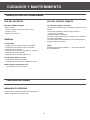
CONFIGURACION Y MANTENIMIENTO
DEL RECEPTOR
4. Coloque un amplificador en la parte superior para que
el aire caliente suba y no afecte al resto de aparatos. Si
dispone de un receptor satélite, sitúelo en la parte más alta.
1.Provea de espacio suficiente para la ventilación:
15cm/6"
ST ER EO R EC EI VE R AMP LI FI ER
10cm/
4"
10cm/
4"
15cm / 6"
10cm/
4"
2. No conecte el cable de red antes de realizar todas
las conexiones.
3. Permita la adecuada ventilación de la unidad, colocándola
sobre un soporte adecuado.
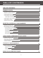
TABLA DE CONTENIDOS
TABLA DE CONTENIDOS
18
PRIMEROS PASOS
19
DESEMBALANDO EL RECEPTOR
19
SOBRE EL CONTROL REMOTO
20
CONEXIONES BASICAS
21
CONECTANDO LOS ALTAVOCES
22
CONECTANDO LOS CABLES
22
CONECTANDO LOS ALTAVOCES
22
CONECTANDO LAS ANTENAS
22
CONECTANDO LA RED
23
USANDO AURICULARES
23
RECEPTOR, CONTROLES Y FUNCIONAMIENTO
24
24
INTRODUCCION AL PANEL
MENSAJES EN PANTALLA
SINTONIZANDO EL RECEPTOR
25
25
25
25
25
26
26
26
26
SELECCCIONANDO LA BANDA AM/FM
SINTONIZACION MANUAL
AUTO TUNING
ALMACENANDO EMISORAS EN MEMORIA
ALMACENAR EMISORAS
PRESET MANUAL
RECUPERANDO EMISORAS ALMACENADAS
CONECTANDO COMPONENTES AUXILIARES
27
INTRODUCCION AL PANEL TRASERO
27
ANTES DE CONECTAR
28
CONECTANDO UN REPRODUCTOR DE CD
28
CONTROL REMOTO
29
CUIDADOS Y MANTENIMIENTO
30
30
RESOLUCION DE PROBLEMAS
30
30
30
30
USO DEL RECEPTOR
USO DEL CONTROL REMOTO
GENERAL
LIMPIEZA EXTERNA
ESPECIFICACIONES DEL EQUIPO
18
31
PRIMEROS PASOS
DESEMBALANDO EL RECEPTOR
Debería recibir los siguientes elementos:
Un receptor AM 105
Un control remoto
ST ER EO R EC EI VE R AM PL IFI ER
Antena interna de FM
VCR
AUX
POWER
CD
DVD
TUNER
A
1
2
B
3
4
C
5
6
D
7
8
SLEEP
AM/FM
MEMORY
BALANCE
MUTE
AUTO
VOL
SCAN
BASS
TREBLE
AM-105
Antena de AM
Pilas AAA, R3
Manual de instrucciones
19
PRIMEROS PASOS
SOBRE EL CONTROL REMOTO
INSTALANDO LAS PILAS EN EL
CONTROL REMOTO
RANGO DE USO DEL MANDO REMOTO
Debido a que el mando remoto se usa para muchas
funciones, debe empezar por instalar las pilas.
1. Gire el mando y deslice hacia afuera la cubierta del
compartimento de las pilas.
ST ER EO R EC EI VE R AM PL IF IE R
2. Inserte las pilas tipo AAA incluidas de acuerdo a la
polaridad marcada en el interior del compartimento.
3. Cierre la tapa del compartimento.
Aproximadamente
6m(19.7feet)
30
30
PRECAUCION
Peligro de explosión si las pilas son
sustituidas incorrectamente.
VCR
AUX
POWER
CD
DVD
TUNER
A
1
B
3
4
C
5
6
2
D
7
8
SLEEP
AM/FM
MEMORY
BALANCE
MUTE
AUTO
VOL
SCAN
BASS
TREBLE
NOTAS ACERCA DEL MANDO REMOTO
AM-105
Sustitución de las pilas
Si ve que el mando debe ser usado muy cerca de la unidad,
significa que las pilas están agotadas. Sustitúyalas por otras
nuevas.
NOTAS:
NOTAS:
1.Use pilas tipo AAA
1. El área entre el mando remoto y la unidad debe estar
libre de obstáculos.
2. Asegúrese que la polaridad es la correcta (Ver ilustración
dentro del compartimento)
2. No exponga el sensor del mando a fuertes fuentes de luz
en particular luces fluorescentes que podrían hacer que el
mando no funcionara adecuadamente. Si es necesario
modifique la posición de la unidad.
3. Retire las pilas si el mando no va a usarse durante bastante
tiempo.
4. Evite tocar el material interno de la pila si esta rezuma el
electrolito interno. Limpie el compartimento de las pilas antes
de colocar las nuevas.
20
PRIMEROS PASOS
CONEXIONES BASICAS
Asumiendo que dispones de un DVD, los siguientes pasos deben ayudarle rápidamente a configurar su nuevo receptor. Si tiene más
componentes electrónicos, consulte la tabla de contenidos o el indice para encontrar la descripción del conexionado.
- Los cables (adquiridos en una tienda) deben ser de color para ayudarle al conexionado.
1. Usando un cable de audio con conexiones roja y blanca, conecte el jack de audio “OUT” en la toma trasera del DVD (conector IN).
2. Usando el cable de video con conectores amarillos, conecte el jack “OUT” de video a la toma “VIDEO IN” del DVD o “VIDEO
OUTPUT” del televisor. Si hay más de un conector de video, use “VIDEO 1”.
DVD
IN FROM ANT
IN
Ch3
Ch4
OUT
199
VIDEO R
OUT TO TV
L
VIDEO
INPUT
TV
RIGHT
OUT AUDIO
S-VIDEO
L/
MONO
RECEPTOR
DE AUDIO
ST ER EO RE CE IV ER AMP LI FI ER
21
IN
CABLE/
ANTENNA
PRIMEROS PASOS
CONECTANDO LOS ALTAVOCES
CONECTANDO LOS CABLES
1.Afloje los terminales
2. Inserte un cable, pele unos 5 mm de aislante, procedente
de los altavoces.
3.Apriete los terminales, asegurando el cable.
Método 1
O utilice un terminal tipo banana.
Polaridad de los altavoces
Cuando conecte los altavoces, asegúrese de la polaridad “+”
en el cable es la misma que en el receptor. Si los cables
están invertidos, el sonido estará distorsionado y con pocos
graves (efecto de fuera de fase)
Método 2
NOTA:
1. No deje que el cable pelado toque cualquier otra parte
metálica. Podría dañar los altavoces o la unidad.
ALTAVOZ DERECHO
2. Conecte los terminales del altavoz con los altavoces
usando el cable adecuado con conexiones lo más cortas
posibles. Si los conectores fallan no se escuchará nada.
CONECTANDO LOS ALTAVOCES
Los dos altavoces principales deben ser situados entre 2 y
3 metros de separación entre ellos. Colocándolos más cerca
pueden distorsionar el sonido. Los altavoces deben estar
en un ángulo de 45º del punto central de escucha de la
unidad, creando un triángulo.
CONECTANDO LAS ANTENAS
Las antenas AM y FM se conectan a los terminales AM y FM
del panel trasero de la unidad. Deben ser desplegadas para
una recepción clara. Desenrolle el cable de la antena y localice
el terminal. Presione los terminales e inserte el cable.
Compruebe el conexionado y extienda la antena en su totalidad
ajustando la posición para una recepción correcta.
22
ALTAVOZ IZQUIERDO
PRIMEROS PASOS
CONECTANDO LA RED
Asegúrese que conecta todos los otros componentes
electrónicos antes del conectar el receptor a la red.
Conecte el cable de red en la toma mural adecuada.
Asegúrese que la toma dispone de conexionado
a tierra.
Inserte el conector completamente en la toma mural.
USANDO AURICULARES
Para escuchar de manera más privada el sistema de audio, use la toma de auriculares del receptor. Asegúrese de bajar el
volumen antes de colocarse los auriculares, incrementando el volumen al nivel adecuado después de colocarse los
auriculares en su sitio.
Para una audición confortable
1. No use los auriculares al máximo volumen. No
es muy adecuado para una audición prolongada.
2. Si experimenta zumbidos en sus oidos, reduzca
el volumen o deje de usarlos momentáneamente.
23
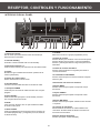
RECEPTOR, CONTROLES Y FUNCIONAMIENTO
INTRODUCCION AL PANEL
1
3
2
4
6
5
STEREO RE CEIVER AMPLIFIER
7
8
9
10
11
12
13
14
15
16
17
18
19
20
11. A/B/C/D
Seleccione uno de los 4 grupos pregrabados (A a D)
1. Selector de entrada
Gire el mando para seleccionar la fuente de entrada que
desea escuchar o visualizar.
12. Botón de escaneo
Presione SCAN+ para escanear a una frecuencia superior.
Presione SCAN- para escanear a una frecuenciainferior.
Presione y mantenga durante dos segundos para esceno
automático.
2. Indicador Standby
Se ilumina cuando la unidad está en modo Standby
3. Botones de números 1-8
Presione estos botones para seleccionar el canal almacenado
13. Botón de escaneo automático
Presione esta tecla durante 3 segundos para iniciar el
escaneo automático.
4. Display
Muestra una gran variedad de información (Volumen de la
fuente o parámetros)
14. Conmutador banda AM/FM
Presione esta tecla para conmutar la banda de recepción
entre FM y AM.
5. Sensor del control remoto
Recibe señal desde el mando remoto
15. Almacenar una emisora en memoria
6. Volumen Master
Controla el nivel de salida de todos los canales de audio
16. Ajuste BASS
Presione esta tecla para ajustar la respuesta a bajas
frecuencias
7. Interruptor POWER
Presiónelo para encender la unidad. Presione otra vez para
apagarlo.
17. Ajuste TREBLE
Presione esta tecla para ajustar la respuesta a altas
frecuencias
8. Botón Standby
Presione esta tecla para pasar a modo standby. Presione
otra vez para salir de este modo.
18. Ajuste BALANCE
Presione esta tecla para ajustar el balance entre derecha
e izquierda
9. MUTE
Corta el sonido. Presione otra vez para restaurar la salida
de audio al valor previo.
19. Conector de auriculares
Permite disfrutar del sistema de audio mediante unos
auriculares. No habrá señal de salida en los altavoces
al conectar los auriculares.
10. Botón SLEEP
Presione repetidamente esta tecla para marcar el tiempo de
encendido/apagado sleep y configurarlo (10,20,30,40,50,60,
70,80,90 minutos).
20. Ajuste del brillo del display
Presione par ajustar el brillo del display
24
RECEPTOR, CONTROLES Y FUNCIONAMIENTO
MENSAJES EN PANTALLA
Lo siguiente es un ejemplo de todos los mensajes que puede encontrar mientras usa un receptor. Para el mensaje específico
diríjase a cada sección
STEREO TUNED
L
R
SLEEP
MEMORY
KH z
MH z
SLEEP
STEREO
Emisora en estéreo detectada.
Unidad en modo sleep
KHz
MHz
TUNED
Emisora detectada
Unidades de frecuencia de recepción
SINTONIZANDO EL RECEPTOR
SELECCIONANDO LA BANDA AM/FM
AUTO TUNING
1. Pulse latecla AM/FM del panel frontal o en el mando
remoto para activar el sintonizador.
Use esta función para buscar emisoras automáticamente.
Presione y mantenga la tecla AUTO durante 3 segundos en
el mando. Las emisoras localizadas se grabarán
automáticamente.
Cuando todas las emisoras disponibles se hayan grabado o
llegado al tope de 32 emisoras, la función auto se parará.
2. Cuando use el mando remoto, debe presionar la tecla
AM/FM otra vez para cambiar de banda.
SINTONIZACION MANUAL
NOTA
Presione la tecla SCAN + en el mando para desplazarse
para arriba en la bande de frecuencia. Presione SCAN para desplazarse hacia abajo en la bande de frecuencia.
Debe pulsar y retener las teclas SCAN + y - para
ir automáticamente a la siguiente emisora.
Una señal débil puede afectar a la función de auto-busqueda
Ajuste la antena para una mejor recepción.
NOTAS:
1. Si hay interferencia, modifique la localización de la antena
hasta que el sonido escuchado sea óptimo. TV y otros
dispositivos electrónicos pueden causar interferencias, trate
de alejar la antena de estos dispositivos.
2. Una señal debil puede afectar la función de auto-busqueda
Ajuste la antena para una mejor recepción
25
RECEPTOR, CONTROLES Y FUNCIONAMIENTO
ALMACENANDO EMISORAS EN MEMORIA
RECUPERANDO EMISORAS ALMACENADAS
Puede almacenar hasta 32 emisoras de Am y FM, estas
emisoras pueden almacenarse en orden aleatorio.
1. Gire el mando INPUT en el panel frontsal o presione TUNER
en el mando remoto para seleccionar TUNER como fuente
de entrada.
ALMACENAR EMISORAS
2. Presione A/B/C/D en el panel frontal o en el mando
para seleccionar el grupo de emisoras almacenadas que desee
1. Presone la tecla AM/FM del panel frontal o mando remoto
para seleccionar la banda de recepción.
3. Presione el número 1-8 en el mando remoto para seleccionar
el número de la emisor almacenada, La emisora se muestra
en la pantalla.
2,. Seleccione la emisora que desea almacenar usando los
métodos descritos antes.
4. De la misma manera puede seleccionar otras emisoras
seleccionadas.
3. Presione la tecla MEMORY en el mando, “MEMORY”
parpadeará en pantalla. Mientras lo hace, presione el
número que desea para almacenar la emisora.
Si el indicador de memoria en la pantalla
se apaga antes de poder seleccionar
la emisora, presione MEMORY otra
vez.
PRESET MANUAL
1. Seleccione la banda presionando AM/FM
1. Sintonice la emisora de radio (lea la sección “sintonización
manual”)
3. Seleccione el grupo (A-D) de las emisoras almacenadas. Este
grupo se mostrará en la pantalla. P. Ejem “A”
4. Presione MEMORY en el mando remoto. “MEMORY”
aparecerá en pantalla.
5. Mientras “MEMORY” está en pantalla, presione la tecla
preset deseada 1-8 para seleccionar el número de emisora
almacenado. P:Ejem si el número es “1”, aparece “MEM OK”
en pantalla. La emisora ha sido almacenada en “A1”
6. Repita los pasos 1 a 5 para almacenar las otras emisoras
26
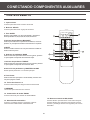
CONECTANDO COMPONENTES AUXILIARES
INTRODUCCION AL PANEL TRASERO
1
2
3
4
5 6 7 8 9 10 11
12
9. Salida audio REC
1.Entrada de antena FM
NOTA:
2. Entrada de antena AM
El nivel es controlado por el volumen Master
3. Salida de altavoces del canal derecho
10. Conector Pre out
4. Salida de altavoces de canal izquierdo
NOTA:
Un puente se usa entre los conectores 10 y 11.
5. Entrada de audio VCR
11. Entrada del amplificador
6. Entrada AUX
NOTA:
7. Entrada audio CD
Un puente se usa entre los conectores 10 y 11.
8. Entrada audio DVD
12. Toma de red AC 230V/50Hz
27
CONECTANDO COMPONENTES AUXILIARES
ANTES DE CONECTAR ....
CONECTANDO LOS CABLES
POSICIONE LOS CABLES CORRECTAMENTE
- Proteja los equipos de subidas de potencia
- Conecte todos los componentes antes de conectar el cable
de red dentro de la clavija mural.
- Apague siempre el receptor y los otros componentes antes
de conectar o desconectar los cables.
- Compruebe que el color de los cables y los terminales es
el correcto.
- Los colores de cables de conexionado y conectores son l
os siguientes:
Terminales de altavoz: Rojo para positivo (+), negro para
negativo (-).
- Algunas unidades para este conexionado pueden venir
en vez de rojo-negro, en colores rojo-blanco, en este caso
el negro es sustituido por el blanco.
PARA EVITAR ZUMBIDOS O INTERFERENCIAS
- Inserte todos los conectores firmemente en su lugar.
- Coloque los cables de audio y video en el panel trasero
después de conectar todas las unidades.
- Trate de no desplegar ningún cable de red sobre los cables
de audio o video.
- Asegúrese que los cables de antenas están correctamente
conectados a masa.
CONECTANDO UN REPRODUCTOR DE CD
Usando un cable pareado estéro, conecte su receptor
a un reproductor de CD como muestra la figura
adjunta.
Para ejecutar el CD, ponga en marcha la unidad CD y
pase a modo CD en el receptor.
CD
PLAYER
L
199
NOTA:
La conexión de la fuente de audio puede ser usada como
entrada para cualquier señal estereo
AUDIO
RECEIVER
STER EO REC EIVE R AMPLI FIER
28
R
CONECTANDO COMPONENTES AUXILIARES
CONTROL REMOTO
1. Input selector
Presione para seleccionar la fuente de entrada
2. Botones A/B/C/D
Presione para seleccionar el grupo de emisoras
3 Tecla SLEEP
VCR
AUX
POWER
CD
DVD
TUNER
A
1
2
B
3
4
C
5
6
9
Presione para habilitar o no la función SLEEP y seleccionar
el tiempo SLEEP 10,20,30,40,50,60,70,80,90 minutos
1
4.Selector de parámetros BALANCE
Presione para seleccionar el parámetro de balance, entonces
presione “8” para ajustar el balance entre derecha e izquierda
10
2
5.MUTE
Cortsa el sonido. Presione otra vez para restaurar la salida de
audio al volumen previo.
D
7
8
SLEEP
AM/FM
MEMORY
BALANCE
MUTE
AUTO
3
11
4
6. Selector de parámetro BASS
VOL
5
12
13
SCAN
BASS
6
Presione esta tecla para seleccionar los tonos graves, presione
“8” para ajustar la respuesta de frecuencias bajas.
TREBLE
14
7
8
7.Selector de parámetro TREBLE
Presione esta tecla para seleccionar los tonos agudos, presione
“8” para ajustar la respuesta de frecuencias altas.
8.Selección de parámetros y MASTER VOLUME
Permite ajustar parámetros o el volumen principal
9.Tecla Power
Presione esta tecla para pasar a modo standby. Presione otra
vez para apagar la unidad.
10. Teclas de número 1-8
Presione estas teclas para elegir la emisora almacenada
11.MEMORY
Use la tecla para memorizar una emisora
12. Conmutador de banda FM/AM
Presione esta tecla para cambiar de banda AM/FM
14. Botones sintonía SCAN+,SCAN13. Sintonización automática
Presione SCAN+ para sintonizar a frecuencias mayores
Presione SCAN- para seleccionar frecuencias menores
Presione y mantenga durante dos segundos para scaneo
automático
Presione y mantenga durante 3 segundos, todas las
emisoras serán almacenadas automáticamente
29
CUIDADOS Y MANTENIMIENTO
RESOLUCION DE PROBLEMAS
USO DEL CONTROL REMOTO
USO DEL RECEPTOR
Indicador STEREO apagado
-
Ajuste la
La señal
La señal
Zumbido
La unidad no obedece al mando
- Otra función es seleccionada en el mando. Presione la función
correcta.
- No hay pilas insertadas. Coloque las pilas antes de
hacer funcionar el mando
- Baterias agotadas. Sustitúyalas
- El mando no apunta al sensor de la unidad o hay un obstáculo
entre ambos dispositivos.
- El mando remoto está demasiado lejos de la unidad principal
Acerque el mando a la unidad.
antena
es débil, conecte una antena externa
es mono
o ruido severo
GENERAL
No hay audio.
NOTA:
Asegúrese de respetar la polaridad + y - de las pilas marcadas
en el compartimento.
- Asegúrese que el indicador MUTE está apagado
- Asegúrese que los altavoces están conectados
- Compruebe las conexiones
- Compruebe que el puente entre PRE OUT y AMP IN
del panel trasero está insertado
- Compruebe la conexión del cable de red
No hay audio desde un canal.
- Compruebe el cableado del altavoz
- Compruebe la conexión entre la unidad y el altavoz
Ruido cuando se enciende la TV
TV demasiado cerca de la unidad
LIMPIEZA EXTERNA
LIMPIANDO EL EXTERIOR
- Desconecte la unidad de la toma AC antes de limpiar el
exterior del sistema con un paño suave.
30
ESPECIFICACIONES DEL EQUIPO
SECCION AMPLIFICADOR
Canales derecho e izquierdo................................................................................................2X100W
Relación S/N (A weight)..........................................................................................................85dB
Respuesta de frecuencia................................................................................20Hz-20 KHz+/-1.5 dB
SECCION SINTONIZADOR AM
Respuesta de frecuencia................................................................................80Hz 2.3 KHz +/- 6dB
Sensibilidad................................................................................................. ....55dBu @ S/N 20 dB
Relación S/N.......................................................................................................................38 dB
Ratio imagen...................................................................................................... 30 dB @ 1000KHz
Rechazo IF ...........................................................................................................................40 dB
SECCION SINTONIZADOR FM
Respuesta de frecuencia...................................................................................... 40Hz-15 KHz+/- 3dB
Quieting................................................................................................................................24 dBu
Relación S/N........................................................................................... 60 dB (stereo)/65 dB (mono)
Ratio imagen..............................................................................................................................40dB
Rechazo IF................................................................................................................................ 65dB
Especificaciones y características sujetas a cambio sin previo aviso
31
Equipson, S.A.
www.equipson.es
[email protected]