1
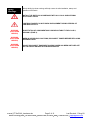
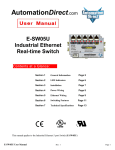
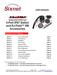
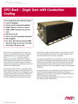
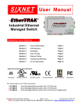
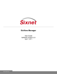
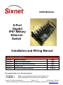
USER MANUAL 8-Port Gigabit IP67 Military Ethernet Switch Installation and Wiring Manual Contents at a Glance: Section 1 General Information Page 3 Section 2 Mechanical and Installation Page 6 Section 3 Power and Communication Wiring Page 7 Section 4 Pressure Vent Page 11 Section 5 Service and Contact Information Page 12 This manual applies to the following products: ET-8EG-MIL-1 ET-8MG-MIL-1 Military unmanaged Ethernet switch with 8 Gigabit ports Military managed Ethernet switch with 8 Gigabit ports manual_ET-8xG-MIL_hardware.doc Page 1 of 12 Last Revised: 17-Aug-09 Sixnet Technology Park 331 Ushers Road Ballston Lake, NY 12019 USA +1-518-877-5173 [email protected] Sixnet Protected Technology Policy - Sixnet protects your investment in Sixnet systems with longterm planned technology and our unique Protected Technology Policy. We will continue to support the specified capabilities of standard Sixnet products for at least five years (twenty years for Industrial Managed Switches). We plan each product improvement and new feature to be upward compatible with existing designs and installations. Our goals are to make each new software release bring new power to your Sixnet systems and have every existing feature, applications program and data file continue to work. We protect your investment even further with a liberal five-year trade-in policy. Exchange standard products for upgraded versions of the same product to take advantage of new features and improvements at any time for five years. A prorated trade-in allowance will be given for your existing unit. Sixnet protects your longterm productivity with state-of-the-art planned technology and continued support. Sixnet Statement of Limited Warranty - Sixnet, manufacturer of Sixnet products, warrants to Buyer that products, except software, manufactured by Sixnet will be free from defects in material and workmanship. Sixnet's obligation under this warranty will be limited to repairing or replacing, at Sixnet's option, the defective parts within one year of the date of installation, or within 18 months of the date of shipment from the point of manufacture, whichever is sooner. Products may be returned by Buyer only after permission has been obtained from Sixnet. Buyer will prepay all freight charges to return any products to the repair facility designated by Sixnet. This limited warranty does not cover losses or damages which occur in shipment to or from Buyer or due to improper installation, maintenance, misuse, neglect or any cause other than ordinary commercial or industrial applications. In particular, Sixnet makes no warranties whatsoever with respect to implied warranties of merchantability or fitness for any particular purpose. All such warranties are hereby expressly disclaimed. No oral or written information or advice given by Sixnet or Sixnet’s representative shall create a warranty or in any way increase the scope of this warranty. This limited warranty is in lieu of all other warranties whether oral or written, expressed or implied. Sixnet's liability shall not exceed the price of the individual units, which are the basis of the claim. In no event shall Sixnet be liable for any loss of profits, loss of use of facilities or equipment, or other indirect, incidental or consequential damages. INSTALLATION WARNINGS - These products should not be used to replace proper safety interlocking. No software-based device (or any other solid-state device) should ever be designed to be responsible for the maintenance of consequential equipment or personnel safety. In particular, Sixnet disclaims any responsibility for damages, either direct or consequential, that result from the use of this equipment in any application. All power, input and output (I/O) wiring must be in accordance with Class I, Division 2 wiring methods and in accordance with the authority having jurisdiction. Refer to section 1 for other important installation warnings. FCC Statement - This equipment has been tested and found to comply with the limits for a Class B digital device, pursuant to Part 15 of the FCC Rules. These limits are designed to provide reasonable protection against harmful interference in a residential installation. This equipment generates, uses and can radiate radio frequency energy and, if not installed and used in accordance with the instructions, may cause harmful interference to radio communications. However, there is no guarantee that interference will not occur in a particular installation. If this equipment does cause harmful interference to radio or television reception, which can be determined by turning the equipment off and on, the user is encouraged to try to correct the interference by one or more of the following measures: Reorient or relocate the receiving antenna; Increase the separation between the equipment and receiver; Connect the equipment into an outlet on a circuit different from that to which the receiver is connected; Consult the dealer or an experienced radio/TV technician for help. Copyright & Trademarks - Copyright 2008 Sixnet, LLC. All Rights Reserved. Note: All information in this document is subject to change without notice. manual_ET-8xG-MIL_hardware.doc Page 2 of 12 Last Revised: 17-Aug-09 Sixnet Technology Park 331 Ushers Road Ballston Lake, NY 12019 USA +1-518-877-5173 [email protected] Section 1 Overview General Specifications This manual will help you install and maintain the switch which is offered as unmanaged (model ET-8EG-MIL-1) or managed (model ET-8MG-MIL-1). The unmanaged model requires no configuration and is completely “plug and play”. The managed model allows you to configure the switch to optimize and increase network performance. Note: This manual only covers the installation and wiring of these switches. For the managed model, refer to the separate Software User Manual for details on configuring and using any of the management functions such as SNMP, RSTP, IGMP, port mirroring, etc. Basic Operation Unlike an Ethernet hub that broadcasts all messages out all ports, these industrial Ethernet switches will intelligently route Ethernet messages only out the appropriate port. The major benefits of this are increased bandwidth and speed, reduction or elimination of message collisions, and deterministic performance when tied with real-time systems. The switch supports 10BaseT (10 Mbps), 100BaseT (100 Mbps) and 1000BaseT (1000 Mbps) on 8 ports. Each of these ports independently and automatically senses the speed and duplex for best performance. They also offer auto-crossover and auto-polarity to assure a proper link with either straight or crossed wired cables or even when the cable is incorrectly wired. Performance Specs The switch has the following performance specifications. Note: All specifications are subject to change. Consult factory for latest information. E T H E R N E T P E R F O R MA N C E 8 Gigabit Ethernet ports for 10/100/1000 Mbps links Store & forward wire-speed non-blocking switching Managed or unmanaged model available All IEEE 802.3 Ethernet protocols supported Auto-negotiation for Ethernet speed and duplex Auto-crossover for Ethernet MDI/MDIX wiring Auto-polarity for Ethernet TD and RD polarity Full or half duplex operation (auto or configurable) 8192 MAC addresses supported 32 Gbps Memory bandwidth Ethernet isolation 1500 VRMS 1 minute Connector: MIL-STD-38999 series III receptacle with shell/insert style 9-9, 9 socket contacts & N keying E T H E R N E T C O MPL I A N C E IEEE 802.3 (Original Ethernet 10Mbps) IEEE 802.3u (Fast Ethernet 100Mbps) IEEE 802.3z (Gigabit Ethernet 1000Mbps) IEEE 802.3x (Full-Duplex with Flow Control) And many more manual_ET-8xG-MIL_hardware.doc Page 3 of 12 Last Revised: 17-Aug-09 Sixnet Technology Park 331 Ushers Road Ballston Lake, NY 12019 USA +1-518-877-5173 [email protected] POWER INPUT Connector: MIL-STD-38999 Series III receptacle with shell size A, style 98, 3 pin contacts and A keying Input voltage range: 10-30 VDC (continuous) Input power: 12 W (typical under full load) Reverse polarity protection Exceeds MIL-STD-1275 for power protection Military surge protection: 100 volts for 1 second Transient protection: 15,000 watts peak Spike protection: 5,000 watts (10x for 10 uS) or 250 volts (50x for 100 uS) ENVIRONMENTAL Operating temperature: -40 to +75°C (cold startup at -40°C) Storage temperature: -40 to +85 °C Humidity (non-condensing) 5 to 95% RH Vibration, shock and freefall per MIL-STD-810F and IEC68-2-6, -27 and -32 Vent plug for high altitude operation PHYSICAL Dimensions (L x W x H) 11 x 6 x 2.85” (279 x 152 x 72 mm) Weight (including caps) 3.5 lbs (1.6 Kg) IP67 dust, oil and water-tight package protection Connectors and caps: olive-drab-green cadmium Case: olive-drab-green plating S T A N D A R D S C O MPL I A N C E MIL-STD-461E for EMC performance MIL-STD-810F for environmental performance MIL-STD-1275B for power protection FCC part 15 / ICES-003; EN55022 ; IEC61326-1 MANAGED MODELS USB / RS232 console port via MIL-STD-38999 series III connector w/ shell size A, style 35, 6 contacts & A keying Rapid Spanning Tree (RSTP) for fault-tolerant loops Priority queuing for real-time performance SNMP v1 and V2 for network management SNMP v3 for authentication and encryption SNMP notifications (traps) for report on event IGMP v1 & v2 for IP multicast filtering VLAN (port & tag based) for traffic segregation Message filtering to stop broadcast/multicast storms RMON and port mirroring for diagnostics Configuration via secure (https) Web interface, Telnet / SSH (network), terminal (RS232) or SNMP (v1, v2, v3) And much more (Contact us for latest features list) manual_ET-8xG-MIL_hardware.doc Page 4 of 12 Last Revised: 17-Aug-09 Sixnet Technology Park 331 Ushers Road Ballston Lake, NY 12019 USA +1-518-877-5173 [email protected] Safety Warnings Strictly abiding by these warnings will help ensure the safe installation, startup and operation of the switch. INSTALL THE SWITCH IN ACCORDANCE WITH ALL LOCAL AND NATIONAL ELECTRICAL CODES. LIGHTNING DANGER: DO NOT WORK ON EQUIPMENT DURING PERIODS OF LIGHTNING ACTIVITY. WARNING (EXPLOSION HAZARD) SUBSTITUTION OF COMPONENTS MAY IMPAIR SUITABILITY FOR CLASS 1, DIVISION 2 (ZONE 2). WARNING (EXPLOSION HAZARD) WHEN IN HAZARDOUS LOCATIONS, DISCONNECT POWER BEFORE REPLACING OR WIRING UNITS. WARNING (EXPLOSION HAZARD) DO NOT DISCONNECT EQUIPMENT UNLESS POWER HAS BEEN SWITCHED OFF OR THE AREA IS KNOWN TO BE NONHAZARDOUS. manual_ET-8xG-MIL_hardware.doc Page 5 of 12 Last Revised: 17-Aug-09 Sixnet Technology Park 331 Ushers Road Ballston Lake, NY 12019 USA +1-518-877-5173 [email protected] Section 2 Mechanical Dimensions and Installation The switch is designed to be mounted to any flat surface. The oval mounting holes or side slots will accept up to a 0.25 inch or 6.5 mm diameter screws. 2.45" [6.22cm] with plug 2.24" [5.69cm] 5.75" [14.61cm] 0.25" [0.64cm] 0.51" [1.30cm] 6.00" [15.24cm] 5.49" [13.94cm] RS232/USB 6.61" [16.80cm] 9.15" [23.23cm] 11.00" [27.94cm] 10.72" [27.22cm] (managed only) 0.38" [0.95cm] Overview 0.35" [0.89cm] 1.50" [3.81cm] 0.50" [1.27cm] 2.85" [7.24cm] manual_ET-8xG-MIL_hardware.doc 0.38" [0.95cm] 1.20" [3.05cm] Ø0.28" [Ø0.70cm] 0.58" [1.46cm] 0.26" [0.67cm] 1.83" [4.66cm] 4.36" [11.09cm] Power Input 4.70" [11.94cm] Page 6 of 12 Last Revised: 17-Aug-09 Sixnet Technology Park 331 Ushers Road Ballston Lake, NY 12019 USA +1-518-877-5173 [email protected] Section 3 Overview Power and Communication Connections The switch features 38999 Series III style connectors which meet or exceed the MIL-STD38999 standard for military use. All these connectors have EMI shielding, ESD protection, plus moisture and corrosion resistance. All mating connectors will self-lock with one 360 degree turn of the coupling nut. Typical MIL-STD-38999 Connectors (shown with tethered plugs) Typical MIL-STD-38999 Plug (not typically supplied with switch) Grounding Use the provided 8-32 ground stud to connect the switch to a suitable safety, chassis or earth ground. Use of heavy gauge (at least 16 AWG) grounding wire is recommended. Make sure to follow your local or national codes for the proper ground connection. Chassis Ground Connection Point manual_ET-8xG-MIL_hardware.doc Page 7 of 12 Last Revised: 17-Aug-09 Sixnet Technology Park 331 Ushers Road Ballston Lake, NY 12019 USA +1-518-877-5173 [email protected] Power Receptacle The switch requires a positive voltage between 10 and 30 VDC. Make the power connections as shown in the diagram below. Power Receptacle Location + DC Supply - A Power Receptacle Pinout C B No Connection Receptacle: Shell=A, Insert=98, Contacts=P, Keying=A Recommended Military # D38999/26WA98SA Plug (w/ cadmium plating, socket contacts, A keying) manual_ET-8xG-MIL_hardware.doc Page 8 of 12 Last Revised: 17-Aug-09 Sixnet Technology Park 331 Ushers Road Ballston Lake, NY 12019 USA +1-518-877-5173 [email protected] Console Receptacle The managed model of the switch offers a RS232 serial port for accessing the local management interface. Once you have made a physical connection refer to the software user manual on how to access the switch via this console port. Console Receptacle Location (managed model only) RS232 and USB USB-DM Console Receptacle Pinout USB-DP USB-CNX (VBUS) 5 4 5 6 1 GND 4 1 6 3 2 3 RS232-TD (output) 2 RS232-RD (input) Receptacle: Shell=A, Insert=35, Contacts=S, Keying=A Recommended Military # D38999/26WA35PA Plug (w/ cadmium plating, pin contacts, A keying) manual_ET-8xG-MIL_hardware.doc Page 9 of 12 Last Revised: 17-Aug-09 Sixnet Technology Park 331 Ushers Road Ballston Lake, NY 12019 USA +1-518-877-5173 [email protected] Ethernet Receptacle The switch has eight 10/100/1000 Ethernet ports. These ports will auto-detect the speed and duplex of the connection. Alternatively in the managed model, the ports can be disabled or configured for fixed settings via one of the management interfaces. See the software user manual for details. Ethernet Receptacle Location (typical) No Connection 7 DD+ 8 DDEthernet Receptacle Pinout 8 1 DA+ 6 DB- 7 6 5 9 1 4 2 3 2 DA3 DB+ 5 DC4 DC+ Receptacle: Shell-Insert = 9-9, Contacts = S, Keying = N Recommended Amphenol # TV06RW9-9PN Plug (w/ cadmium plating, pin contacts, Normal keying) manual_ET-8xG-MIL_hardware.doc Page 10 of 12 Last Revised: 17-Aug-09 Sixnet Technology Park 331 Ushers Road Ballston Lake, NY 12019 USA +1-518-877-5173 [email protected] Section 4 Pressure Pressure Vent Without a pressure ventilation system the pressure differential that can occur due to temperature or altitude changes can result in condensation. To prevent this the switch incorporates a pressure vent that adjust the internal air pressure to match the surrounding (external) pressure. At the same time the vent is IP67 rated and will not let moisture into the switch. Characteristics of the Pressure vent Air flow rate: Point of water entry: Temperature resistance: 0,4 l/min at 0,1 bar ΔP to 5,0 l/min at 1 bar ΔP 1,5 bar –40°C to +120°C (in assembled state) Pressure Vent manual_ET-8xG-MIL_hardware.doc Page 11 of 12 Last Revised: 17-Aug-09 Sixnet Technology Park 331 Ushers Road Ballston Lake, NY 12019 USA +1-518-877-5173 [email protected] Section 5 Service Information Service Information We sincerely hope that you never experience a problem with any Sixnet product. If you do need service, call Sixnet at (518) 877-5173 and ask for Technical Support. A trained specialist will help you to quickly determine the source of the problem. Many problems are easily resolved with a single phone call. If it is necessary to return a unit to us, an RMA (Return Material Authorization) number will be given to you. Sixnet tracks the flow of returned material with our RMA system to ensure speedy service. You must include this RMA number on the outside of the box so that your return can be processed immediately. The applications engineer you are speaking with will fill out an RMA request for you. If the unit has a serial number, we will not need detailed financial information. Otherwise, be sure to have your original purchase order number and date purchased available. We suggest that you give us a repair purchase order number in case the repair is not covered under our warranty. You will not be billed if the repair is covered under warranty. Please supply us with as many details about the problem as you can. The information you supply will be written on the RMA form and supplied to the repair department before your unit arrives. This helps us to provide you with the best service, in the fastest manner. Normally, repairs are completed in two days. Sometimes difficult problems take a little longer to solve. If you need a quicker turnaround, ship the unit to us by air freight. We give priority service to equipment that arrives by overnight delivery. Many repairs received by mid-morning (typical overnight delivery) can be finished the same day and returned immediately. We apologize for any inconvenience that the need for repair may cause you. We hope that our rapid service meets your needs. If you have any suggestions to help us improve our service, please give us a call. We appreciate your ideas and will respond to them. For Your Convenience: Please fill in the following and keep this manual with your Sixnet system for future reference: Serial #:__________________ Date Purchased: ___________________ Purchased From:______________________________________________ Product Support To obtain support for Sixnet products: Latest product info: http://www.sixnet.com Phone: +1 (518) 877-5173 Fax: +1 (518) 877-8346 E-mail: mailto: [email protected] Mailing address: Sixnet Technology Park, 331 Ushers Road, Ballston Lake, NY 12019 manual_ET-8xG-MIL_hardware.doc Page 12 of 12 Last Revised: 17-Aug-09 Sixnet Technology Park 331 Ushers Road Ballston Lake, NY 12019 USA +1-518-877-5173 [email protected]