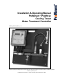
1
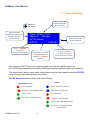
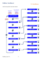
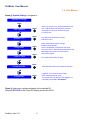
Installation & Operating Manual
ProMinent® ProMtrac
Cooling Tower
Water Treatment Controller
ProMtrac_OM.docx (5/23/13): – pn.
Please completely read through these operating instructions first! Do not discard! The warranty shall be invalidated by damage
caused by operating errors!
ProMinent Fluid Controls, Inc. (USA) 136 Industry Drive, Pittsburgh, PA 15275
ProMtrac User Manual
CONTENTS
Safety
1. Navigation
1.1 Power ON display
1.2 User Menus
1.3 Status Displays
1.4 Browser View
2. Adjust Setpoint
Bleed Solenoid, Inhibitor Pump
3. Calibrate
Conductivity
4. Adjust Alarms
Conductivity, Inhibitor Pump, Water Meters,
Bleed Solenoid
5. Biocide Events
6. Configure
Inhibitor Pump, Bleed Solenoid, Oxidant Pump
Biocide ‘B’, Make-up Meter
7. 4-20mA Outputs
8. Passwords
9. Power Wiring
10. Dry Contact Pump Wiring
11. Sensor & Water Meter Wiring
12. USB flash drive data logs & configuration files
13. Ethernet View-Modify
14. Relay Assignment
ProMtrac_User 5/13
2
ProMtrac User Manual
Safety Electrical Shock Hazard
Removing the lower faceplate panel with the controller plugged in,
exposes the user to AC power line voltages.
USER WARNING : CAUTION
Water Treatment Controllers operate water valves and may pump hazardous,
corrosive and toxic chemicals.
Removing the internal faceplates exposes the user to the risk of electrical
shock at power line voltages.
Understand fully the implications of the control methods, setpoints
and alarms that you select. Harm to personnel and damage to equipment may
result from mis-application.
Unplug or turn OFF the AC power to the controller if you have any concerns
regarding safety or incorrect controller operation and notify supervisory staff.
YOUR CONTROLLER
ProMtrac controllers are supplied in different configurations, part numbers and
sensor sets. This manual includes information on optional components that may
not be included with your controller
The WIRING section includes the information for terminating the sensor, water
meters, AC power, pumps & solenoids
ProMtrac_User 5/13
3
ProMtrac User Manual
1.1
Tower conductivity,
Always displays
Rotate for
user menus
Optional sensors
ORP & Flourescent in this
example alternate
with time-date
Power Up Display
Tower 1234uS 74.6F
386.4 mV
420 ppm
OK, No Alarms
STRTUP
STATUS
Press F1, STARTUP
to walk thru
first time setup wizard
Alarm & flowswitch
Status, alternate
Press F3, STATUS
To scroll thru all I/O
Prime, Configure, Alarms...
If passwords turned ON,
F2, LOGIN displayed. If
logged in F2, LOGOUT
displayed.
The sensors on the 2nd line of the power up display vary with the installed sensor set.
pH or ORP have precedence followed by inhibitor ppm sensors and then make-up conductivity.
The value of each sensor, water meter, solenoid and pump can be viewed by pressing STATUS
or by using the menu which displays on rotation.
OK, No Alarms alternates with the flow switch ON time.
System
Output Relays 1 to 5
RED = alarmed
BLUE = OK, flow, no alarms
FlashRED = OFF stopped by user
FlashBLUE = OFF, no flow
GREEN = ON
RED = alarmed
FlashGREEN = Priming or Test
FlashRED = Load fuse fails
GREEN = OFF, USB drive inserted
FlashGREEN = Upload complete,
remove drive
ProMtrac_User 5/13
4
ProMtrac User Manual
1.2 User Menus
Use the rotary dial to view user menus
Step-by-Step
Start-up
Sensor & Controls
Auto-Off-Prime
Configure
STRTUP
STATUS
Bleed Solenoid
Inhibitor Pump
Power ON Display
Tower 1234uS 74.6F
Conductivity
User Menus
EXIT
PRESS
Adjust Setpoints
Make-up Meter
Inhibitor pump
ORP Sensor
Biocide Events
Biocide ‘A’
PRESS
Biocide ‘B’
PRESS
Bleed Solenoid
Inhibitor Pump
ProMtrac_User 5/13
PRESS
PRESS
PRESS
PRESS
PRESS
PRESS
PRESS
Brominator
System Settings
PRESS
PRESS
Bleed Solenoid
Configure Outputs
PRESS
PRESS
Calibrate
Adjust Alarms
PRESS
5
PRESS
PRESS
PRESS
ProMtrac User Manual
1.2 User Menus
Press @ System Settings navigates to:
System Settings
PRESS
Site Options
Enable I/O
Diagnostic
Time & Date
Communicate
Passwords
PRESS
PRESS
PRESS
PRESS
Select U.S.-metric units, Keypad passwords ON/
OFF, USB log file period, Keypress response,
Alarm Relay re-purpose, Flowswitch type,
LCD flash rate...
Turn ON inputs disabled by Keypad
& Browser users.
12VDC Tubine Meter power voltage.
ProMtrac Serial Number
Current ‘Plug&Feed’ configuration file name
Last system reset, Admin password defaulted Y/N,
Watchdog reset count, Firmware Version,
LCD contrast adjust
Set time & date and day of week.
PRESS
View & modify Ethernet IP address & Netmask
PRESS
Logged in, current user password edit.
Enter ‘Reset Passwords’ code.
This option does not display unless logged in &
Passwords turned ON in Site Options
Press @ other menu options navigates to the selected I/O.
Selecting STATUS at the Power ON display scrolls thru all I/O
ProMtrac_User 5/13
6
ProMtrac User Manual
1.3 Status Displays
PRESS
Clears high & low sensor alarms.
Resets feed limits
Only displays if alarms active
RESET
STATUS Page 1 of 3
Press @ any time to return to the
power-up, summary display
Alarms
Conductivity
High @ 12:20:30
RESET
KEYLOG
Goes to Alarms if alarms
Otherwise goes to Conductivity
Scroll through time stamped
user activity log
KEYLOG
Scroll thru all I/O. Pumps & Solenoids
follow the controlling sensor
View and adjust
High & low alarms, delay on alarm,
set alarm relay,disable alarms
ALARMS
Conductivity
A
2036 uS
1940 min 2112 max
ALARMS
CALIB
Calibrate tower conductivity
CALIB
min-max from midnight or most
recent power OFF-ON.
Measure of float effect on cycles.
Turn ON bleed
TEST
Displays if Bleed OFF
Turns OFF bleed
STOP
Bleed Solenoid
R1
ON: 14.6 min
59.4m ON Today
STOP
CONFIG ADJUST
CONFIG
View & select bleed control
method
ADJUST Adjust setpoint
Time in current bleed cycle & total
bleed time from midnight or power ON
View and adjust
High & low alarms, delay on alarm,
set alarm relay,disable alarms
ALARMS
Make-up Meter
Today 45200 G
2012 1204700G
ALARMS
H
View & select meter type
& volume/contact or ‘K’ factor
CONFIG
CONFIG
Year-to-date total alternates
with total volume/days
Turns OFF pump
& it stays OFF
STOP
Displays if Pump ON
Turn ON Pump
PRIME
Inhibitor pump
R2
OFF:Setpoints
84.4min ON today
PRIME CONFIG ADJUST
If pump ON, dislays time owed.
Display varies with feed control method
ProMtrac_User 5/13
7
CONFIG
View & select feed control method
ADJUST Adjust setpoint
ProMtrac User Manual
1.3 Status Displays
PRESS
View and adjust
High & low alarms, delay on alarm,
set alarm relay,disable alarms
ALARMS
Press @ any time to return to the
power-up, summary display
ORP Sensor
C
348.1 mV
340.4 to 350.4 mV
ALARMS
CALIB
ORP range from midnight or most
recent power OFF-ON.
Turn ON Pump or Brominator
PRIME
Displays if Pump OFF
STOP
Turn OFF Pump or Brominator
4-20mA outputs are
Optional & may not be
installed in your ProMtrac
Turns OFF AUTO
MANUAL
Oxidant Pump
R3
ON: 18.4 min
126.4min ON today
STOP CONFIG ADJUST
‘ON today’ alternates with
‘2 Events Day 4of7’
STATUS Page 2 of 3
ProMtrac’s with pH option
display similar pH Sensor
information
CALIB
Calibrate ORP sensor
View & Adjust PreBleed & Lockout,
Alarms & Feed Cycle days
CONFIG
View, Add & Delete feed events
View-Adjust ORP during events
ADJUST
Adjust setpoint
View & select control sensor and
its 4mA & 20mA setpoints
4-20mA Out #2
E
11.2mA 44.8%
514uS AUTO
MANUAL CONFIG VERIFY
CONFIG
Set to 20mA(span) or 4mA(zero)
& adjust span or zero
VERIFY
Displays loop current and % of full span
and controlling sensor value with mode
ProMtrac’s without ORP or pH
will have a Biocide ‘A’ & ‘B’
Turns ON Pump or Brominator
PRIME
Biocide ‘B’
R4
No Event
4 Events,Day 11of28
PRIME CONFIG EVENTS
If Event running, displays time remaining.
#of Events alternates with time ON today
Turns ON the Alarm Relay
TEST
TEST not available if alarmed
ProMtrac_User 5/13
Alarm Relay
No Alarms
0.0 min ON today
TEST
R5
CONFIG
View & Adjust PreBleed & Lockout,
Alarms & Feed Cycle days
EVENTS
Add, Delete & View feed Events
Alarm Relay R5 may be reconifigured
in System Settings as another Biocide,
Inhibitor or Conductivity control
The scroll order of sensors and pumps varies with
optional cards, control types & disabled-enabled I/O
8
ProMtrac User Manual
1.3 Status Displays
PRESS
View and adjust
High & low alarms, delay on alarm,
set alarm relay,disable alarms
ALARMS
Press @ any time to return to the
power-up, summary display
Temperature
84.5 F
59.4 to 84.5F
ALARMS
F
STATUS Page 3 of 3
Temperature is measured
by the tower conductivity
sensor.
CALIB
CALIB
Calibrate Temperature
ORP range from midnight or most
recent power OFF-ON.
View and adjust
ON & OFF time
alarm relay,disable alarms
ALARMS
Flowswitch
ON: 18.4 min
126.4min ON today
ALARMS
K
Thermal flowswitch @ ‘K’
Mechanical flowswitch @ ‘J’
OFF time alarm could be used to flag a 24/7 tower
outage . ON time alarm to flag a tower ON too long.
View and adjust
ON & OFF time
alarm relay,disable alarms
ALARMS
Low Tank Level
OFF:
0.0 min ON today
ALARMS
J
If using the thermal flowswitch,
‘J’ may be used as a contact
set input.
G
Manual values are logged & can
Be used for control & 4-20mA
outputs.
OFF: when contact set OPEN
Browser connect to invert sense.
View and adjust
High & low alarms, delay on alarm,
set alarm relay,disable alarms
ALARMS
Manual Value
126 ppm
106 to 126 ppm
ALARMS
CALIB
CALIB
Used to enter the result
of a manual chemical test.
Inputs ‘G’, ‘H’ & ‘J’ can be disabled
if not used @ this site
View and adjust
High & low alarms, delay on alarm,
set alarm relay,disable alarms
ALARMS
Flourescence
26.7 ppm
19.4 to 28.0 ppm
ALARMS
D
CALIB
Optional DC isolated 4-20mA
input card
ProMtrac_User 5/13
9
An isolated 4-20mA input is
optional & may not be
installed in your ProMtrac
CALIB
Used to calibrate the 4-20mA
input that represents ppm
ProMtrac User Manual
1.4 Browser View
ProMtracs include a built-in command & control web server with a real time view of your controller
operation.
You can browse with Mozilla’s Firefox or Internet Explorer over an Ethernet connection.
Modifying the controller requires a login.
Disabled inputs are automatically removed from the browser view.
User may switch icons to reflect their site’s usage.
See the ProMtrac Browser Manual for detailed information.
ProMtrac_User 5/13
10
ProMtrac User Manual
2. Adjust Setpoints
PRESS
Turn OFF Bleed Solenoid
STOP
ADJUST Page 1 of 1
Bleed Solenoid
Press to return to the
power-up, summary display
Bleed Solenoid
R1
ON: 1.12 hrs
6.23 hrs ON today
STOP CONFIG ADJUST
R1
Returns Conductivity to current
bleed setpoint
EXIT
Rotate to Adjust alternates with PRESS
Press to Accept
Bleed Solenoid
R1
ON: 1.13 hrs
6.24 hrs ON today
STOP CONFIG ADJUST
PRESS
Press to return to the
power-up, summary display
NOTE: In this example, the Bleed Solenoid
is controlled by a conductivity sensor.
Other control methods may have more
than 1 setpoint.
ProMtrac_User 5/13
11
ADJUST
View and adjust feed setpoint
If solenoid ON, alternates with
actuation time in this bleed cycle.
Turn ON Setpoint
1846 uS
Rotate to Adjust
RESET
ADJUST displays vary with the
control method.
RESET
Setpoint now
1846uS
ProMtrac User Manual
2. Adjust Setpoints
PRESS
Turn ON the Pump
PRIME
ADJUST Page 1 of 1
Inhibitor Pump
Press to return to the
power-up, summary display
Inhibitor Pump
OFF: Setpoints
2.34 hrs ON today
PRIME CONFIG
R2
ADJUST
View-Adjust ON time,
Measure Volume unchanged
NEXT
R2
Returns Volume to current
Volume setpoint
EXIT
Rotate to Adjust alternates with PRESS
Press to Accept
Go BACK to Measure Volume
BACK
Then Feed
26 sec
Rotate to Adjust
BACK
RESET
PRESS
12
Measure Volume
Now 125 Gallons
EXIT
R2
ADJUST
Press to return to the
power-up, summary display
NOTE: In this example, the Inhibitor Pump
is controlled by a water meter, turning ON
for 26 seconds for every 125 Gallons
measured.
ProMtrac_User 5/13
RESET
R2
Rotate to Adjust alternates with PRESS
Press to Accept
Inhibitor Pump
OFF: Setpoints
2.34 hrs ON today
PRIME CONFIG
ADJUST
View and adjust feed setpoint
If Pump ON, displays time owed in
this feed cycle.
Measure Volume
125 G
Rotate to Adjust
NEXT
RESET
ADJUST displays vary with the
control method.
This example uses a meter control
Feed time now
26 seconds
ProMtrac User Manual
3. Calibrate
PRESS
View and adjust
High & low alarms, delay on alarm,
set alarm relay,disable alarms
ALARMS
CALIB Page 1 of 1
Conductivity
Press @ any time to return to the
power-up, summary display
Conductivity
A
2036 uS
1940 min 2112 max
ALARMS
CALIB
Calibrate tower conductivity
CALIB
min-max from midnight or most
recent power OFF-ON.
Measure of float effect on cycles.
Returns the sensor to
it’s factory default
calibration
RESET
Conductivity
New: 2045 uS
Rotate to Adjust
RESET
A
EXIT
Conductivity
A
2045 uS
1940 min 2112 max
ALARMS
CALIB
If you calibrated from the STATUS key, you’ll return
to Conductivity, othewise you’ll view the power ON
display with the revised conductivity
IGNORE
Calibrate fails!
Sensor fouled
Clean & re-test
IGNORE RESET
RESET
EXIT
No change to
Conductivity
PRESS
‘Conductivity’ alternates
With ‘Now: 2012 uS’
Ignore the advice,
calibrate to the new
conductivity (Note 2)
Grab sample & measure
the water @ the sample header
Press to Accept
New value
If there’s a
problem, you’ll get
advice (Note 1)
A
EXIT
EXIT
No change to
Conductivity
Returns the sensor to it’s
factory default calibration
Note 1.
Advice varies with both sensor type and correction required to get to the
user calibration value.
Note 2.
Fouled or filmed conductivity sensor may not track the tower
conductivity & may indicate a make-up water chemistry change or feedcontrol problems
ProMtrac_User 5/13
13
ProMtrac User Manual
4. Adjust Alarms
ALARMS Page 1 of 1
PRESS
View and adjust
High & low alarms, delay on alarm,
set alarm relay,disable alarms
ALARMS
Conductivity
Press @ any time to return to the
power-up, summary display
Conductivity
5021 uS
Alarmed High
ALARMS RESET
A
CALIB
RESET
Resets an active alarm
CALIB
Calibrate conductivity
Rotate to view other I/O
High Alarm
4000 uS
Press to modify
A
No change to
Alarms
EXIT
EXIT
Press to Modify alternates with
Rotate to View
Low Alarm
350 uS
Press to modify
A
EXIT
Press to Modify alternates with
Rotate to View
Delay on Alarm
5.0 min
Press to modify
A
Use Delay on Alarm to block
alarms on transient operating
conditions & nuisance alarms
EXIT
Press to Modify alternates with
Rotate to View
Alarms
Enabled
Press to modify
A
EXIT
Turns OFF High & Low alarms.
Stops alarming on this sensor
Press to Modify alternates with
Rotate to View
Alarm Relay
ON
Press to modify
A
EXIT
ProMtrac_User 5/13
14
When alarm occurs, turns ON
Relay 5, Alarm Relay.
(No effect if Relay 5 is not
an Alarm Relay)
ProMtrac User Manual
4. Adjust Alarms
PRESS
Select to access
feed limit ALARMS
CONFIG
View and adjust
Feed limit alarm,
and Priming time
ALARMS
Turns OFF Feed
Limit & Alarm
ALMOFF
ALARMS Page 1 of 1
Inhibitor Pump
Press to return to the
power-up, summary display
Inhibitor Pump
OFF: Setpoints
2.34 hrs ON today
PRIME CONFIG
Controlled by:
Make-up meter
Using this Method
ADJUST ALARMS
R2
User set feed time,
overrides control
ADJUST
R2
EXIT
PRIME
The inhibitor pump feed limit
resets @ midnight so that you
can control the maximum
amount of chemical fed
each day (Note 1)
Inhibitor Pump
R2
Day Timeout 240 mins
Press to Modify
ALMOFF
EXIT
Press to Modify alternates with
Rotate to View
Inhibitor Pump
Prime time 10 min
Press to Modify
ALMOFF
Turns ON Feed
Limit & Alarm
ALMON
Inhibitor Pump
Prime time 10 min
Alarms disabled
ALRMON
R2
EXIT
In addition to testing a pump or
feed you can use Prime Time to
slug feed.
R2
Control returns to AUTO after
Prime time expires
EXIT
Note 1.
The Inhibitor pump feed limit defaults to OFF on alarm & setting the
Alarm Relay (if Relay 5 is used as an alarm relay) on limit. However these
defaults may be modified or have been modified using the browser
interface or the on-line Plug&Feed app.
ProMtrac_User 5/13
15
ProMtrac User Manual
4. Adjust Alarms
PRESS
View and adjust
High & low alarms,
set alarm relay, disable alarms
ALARMS
ALARMS Page 1 of 1
Water Meters
Press @ any time to return to the
power-up, summary display
Makeup Meter
Today 65400G
2012 1200500G
ALARMS
H
View & Modify Meter
type, scaling, zero meter
CONFIG
CONFIG
Rotate to view other I/O
Volume today
175000 G
Press to modify
H
EXIT
Volume today used to alarm on
tower overflow or leaking basin or
or higher make-up water
conductivity
EXIT
No change to Alarms
Press to Modify alternates with
Rotate to View
Low Alarm
0G
Press to modify
H
EXIT
Low Alarm is checked only
@ midnight & used to alarm on
unexpectedly low volumes.
Never alarms if = 0
Press to Modify alternates with
Rotate to View
Alarms
Enabled
Press to modify
H
Turns OFF High & Low alarms.
Stops alarming on this meter
EXIT
Press to Modify alternates with
Rotate to View
Alarm Relay
ON
Press to modify
H
EXIT
Press to Modify alternates with
Rotate to View
ProMtrac_User 5/13
16
When alarm occurs, turns ON
Relay 5, Alarm Relay.
(No effect if Relay 5 is not
an Alarm Relay)
ProMtrac User Manual
4. Adjust Alarms
PRESS
Select to access
feed limit ALARMS
CONFIG
View and adjust
ON time alarm,
and Test time
ALARMS
Turns OFF ON
time Alarm
ALMOFF
Press to return to the
power-up, summary display
Bleed Solenoid
OFF: Setpoints
4.26 hrs ON today
TEST CONFIG
ALARMS Page 1 of 1
Bleed Solenoid
R1
User set bleed time,
overrides control
ADJUST
Controlled by:
Conductivity
Using this Method
ADJUST ALARMS
R1
EXIT
Bleed Solenoid
ON Timeout 100 mins
Press to Modify
ALMOFF
R1
TEST
The bleed alarm does not turn
OFF the bleed; it alerts you to
problems with the bleed
keeping up with the thermal
load. (Note 1)
ON time is the time
in each bleed ON cycle
(Note 2)
EXIT
Press to Modify alternates with
Rotate to View
Bleed Solenoid
Test time 10 min
Press to Modify
ALMOFF
Turns ON
time Alarm
ALMON
Bleed Solenoid
Prime time 10 min
Alarms disabled
ALRMON
R1
Control returns to AUTO after
Test time expires
EXIT
R1
EXIT
Note 1.
The bleed ON time limit defaults to ON on alarm & setting the Alarm
Relay (if Relay 5 is used as an alarm relay) on limit. However these
defaults may be modified or have been modified using the browser
interface or the on-line Plug&Feed app.
Note 2.
ON time alarms are used for Oxidant, pH Controls & Timed Event,
Biocide Controls. Usually disabled on Biocide controls, they cannot be
disabled on pH controls.
ProMtrac_User 5/13
17
ProMtrac User Manual
5. Biocide Events
If you accessed EVENTS from
EXIT
Adds 1 or more biocide
feed events
ADD
EVENTS Page 1 of 2
STATUS
goes to the Biocide ‘B’ display
Biocide ‘B’
45min @ 7:15, Mon
Rotate to View
ADD
DELETE
R4
EXIT
PRESS
Press to modify
alternates with Rotate to View
Goes to start time
NEXT
Adjust ON time
ON for 46 min
@07:00, Tue
NEXT
BACK
R4
EXIT
DELETE Remove event or all events
Edits the
displayed event
BACK
Previous display
BACK
Previous display
Adjusts the ON time
Goes to start day
NEXT
Adjust start time
R4
Start @ 08:45
ON for 46 minutes
NEXT
BACK
EXIT
Adjusts Start time
Goes to frequency
NEXT
Select start day
Thu
46 min @ 08:45
NEXT
BACK
R4
EXIT
BACK
Selects week day. Selects day & week for
28 day cycles. Not shown for 1 day cycle
In this example,
saves 3 feed Events
SAVE
Select frequency
R4
Alternate days
46min @ 08:45, Thu
SAVE
BACK
EXIT
7 day cycle: Once or Daily or Alternate Days
28 day & 1 day cycles differ
Page 2 of 2
ProMtrac_User 5/13
18
EXIT
No events saved
BACK
Previous display
ProMtrac User Manual
5. Biocide Events
EVENTS Page 2 of 2
Page 1 of 2
Up to 28 events may be set
for each biocide control
Biocide ‘B’
Now 8 Events
Advisory
Press to Exit
PRESS
R4
PRESS
Or any key exits to
power ON display
Press to return to the
power-up, summary display
Biocide ‘B’
45min @ 7:15, Mon
Rotate to View
ADD
DELETE
R4
EXIT
DELETE Remove event or all events
Select event to modify or delete
Deletes displayed
event
1 ONLY
Delete Events
ON for 46 min
@07:00, Tue
1 ONLY
ALL
Biocide ‘B’
No Events Set
Advisory
Press to EXIT
ProMtrac_User 5/13
19
Delete all events for this control
EXIT
ALL
PRESS
Or any key exits to
power ON display
ProMtrac User Manual
6. Configure
PRESS
CONFIG
View or modify
feed setpoints
ADJUST
Returns to current
Feed Method
NOW
Press to return to the
power-up, summary display
Inhibitor Pump
OFF: Setpoints
2.34 hrs ON today
PRIME CONFIG
Controlled by:
Make-up meter
Using this Method
ADJUST ALARMS
Controlled by:
Bleed & Feed
Press to Select
NOW
Bleed & Feed and
Bleed then Feed use
% of bleed ON time as
the setpoint
Controlled by:
Bleed then Feed
Press to Select
NOW
Bleed Meter not
displayed if meter
disabled.
Controlled by:
Bleed Meter
Press to Select
NOW
CONFIG Page 1 of 1
Inhibitor Pump
R2
ADJUST
R2
EXIT
R2
EXIT
R2
EXIT
R2
EXIT
View and adjust
Feed limit alarm,
set alarm relay, disable alarms
ALARMS
Changes feed Method
to Bleed & Feed
PRESS
Changes feed Method
to Bleed then Feed
PRESS
Changes feed Method
to Bleed Meter
PRESS
Percent Time, base feed Method
displays, skipped in this example
Fluorescent ppm not
displayed if optional
card not installed
ProMtrac_User 5/13
Controlled by:
Fluorescent ppm
Press to Select
NOW
20
R2
EXIT
Changes feed Method
to ppm sensor control
PRESS
ProMtrac User Manual
6. Configure
PRESS
CONFIG
View or modify
bleed setpoints
ADJUST
Returns to current
Feed Method
NOW
Displayed only if a
Make-up conductivity
sensor installed
Limited to sites with
constant make-up
chemistry
Used as a back-up
method for sites
without water meter(s)
ProMtrac_User 5/13
CONFIG Page 1 of 1
Bleed Solenoid
Press to return to the
power-up, summary display
Bleed Solenoid
OFF: Setpoints
8.12 hrs ON today
TEST
CONFIG
R1
View or modify
bleed setpoints
ADJUST
Controlled by:
Conductivity
Using this Method
ADJUST ALARMS
R2
EXIT
Controlled by:
R2
Make-up / Bleed Meter
Press to Select
NOW
EXIT
Controlled by:
R2
Tower / Make-up Ratio
Press to Select
NOW
EXIT
Controlled by:
Make-up Meter
Press to Select
NOW
Controlled by:
Percent Time
Press to Select
NOW
21
R2
EXIT
R2
EXIT
ADJUST
View and adjust
Bleed limit alarm,
set alarm relay, disable alarms
ALARMS
Changes Bleed Method
& goes to Setpoint Adjust
PRESS
Changes Bleed Method
& goes to Setpoint Adjust
PRESS
Changes Bleed Method
& goes to Setpoint Adjust
PRESS
Changes Bleed Method
to Percent Time
& goes to Adjust Setpoint
PRESS
ProMtrac User Manual
6. Configure
PRESS
View & Modify: Prebleed,
Lockout, Event Cycle &
ORP setpoint during Events
CONFIG
CONFIG Page 1 of 1
Oxidizing Biocides
Press to return to the
power-up, summary display
Oxidant Pump
R3
ON: 38.4 min
4 Events Day 6 of 7
STOP
CONFIG ADJUST
View and adjust ORP setpoint
ADJUST
#of Events & event cycle
alternates with ON time today
PRESS
Press or Adjust
Modifies Prebleed
minutes
ADJUST
Event Controls:
R3
Prebleed 5 minute
Rotate for options
ADJUST ALARMS EXIT
View and adjust
Feed limit alarm,
set alarm relay, disable alarms
ALARMS
Rotate counter-clockwise to
Event ORP setpoint. Clockwise
displays Prebleed, Lockout...
Press or Adjust
Modifies ORP Setpoint
during events
PRESS
ADJUST
Returns the ORP to the
current Event setpoint
RESET
Event Controls:
R3
ORP 650mV on Event
Rotate to Adjust
ADJUST ALARMS EXIT
Event Controls:
R3
ORP 735mV on Event
Rotate to Adjust
RESET EXIT
Rotate to Adjust alternates with
Press to Accept
ProMtrac_User 5/13
Press to return to the
power-up, summary display
22
Leaves the current ORP
Event setpoint unchanged.
EXIT
PRESS
Oxidant Pump
R3
ON: 38.4 min
4 Events Day 6 of 7
STOP
CONFIG ADJUST
PRESS
Use event ORP setpoint to
control @ high oxidant levels
during events
ORP Event setpoint
Now 735 mV
ProMtrac User Manual
6. Configure
PRESS
View & Modify: Prebleed,
Lockout & Event Cycle
CONFIG
Press to return to the
power-up, summary display
Biocide ‘B’
R4
ON: Owes 9.5 min
3 Events Day 1 of 1
STOP
CONFIG EVENTS
CONFIG Page 1 of 1
Non-Oxidizing Biocides
This example shows an active
Event, ON for another 9.5 minutes
#of Events & event cycle
alternates with ON time today
PRESS
Press or Adjust
Modifies Prebleed
minutes
ADJUST
Event Controls:
R4
Prebleed 5 minute
Rotate for options
ADJUST ALARMS EXIT
Rotate for Options alternates
with Press to Adjust
PRESS
Press or Adjust
Modifies Prebleed
conductivity
ADJUST
PRESS
Press or Adjust
Modifies Prebleed
conductivity
ADJUST
PRESS
Press or Adjust
Modifies Prebleed
conductivity
ProMtrac_User 5/13
ADJUST
Event Controls:
R4
Prebleed to 500uS
Press to Adjust
ADJUST ALARMS EXIT
Event Controls:
R4
Lockout 120 minutes
Press to Adjust
ADJUST ALARMS EXIT
Event Controls:
R4
7 Day Event Cycle
Press to Adjust
ADJUST ALARMS EXIT
23
View and adjust
Feed limit alarm,
set alarm relay, disable alarms
ALARMS
Prebleed starts when an Event
starts, delaying feed for Prebleed
time OR Conductivity less than
Prebleed conductivity
Lockout starts after Prebleed ends,
turning OFF the bleed solenoid
to prevent loss & dilution of the
biocide
Event Cycles may be set to
1 Day, 7 Day or 28 Day.
ProMtrac User Manual
6. Configure
PRESS
View and adjust
High & low alarms, delay on alarm,
set alarm relay,disable alarms
ALARMS
CONFIG Page 1 of 1
Water Meters
Press @ any time to return to the
power-up, summary display
Makeup Meter
Today 65400G
2012 1200500G
ALARMS
H
View & Modify Meter
type, scaling, zero meter
CONFIG
CONFIG
Rotate to view other I/O
Volume/contact
100 G
Press to modify
H
Displays Volume/contact for
Contact Meter & ‘K factor for
Turbine Meter.
EXIT
EXIT
No change to Meter
Press to Modify alternates with
Rotate to View
Meter Type
Contact Meter
Press to modify
H
Meter Type is either Contact
Meter or Turbine Meter.
EXIT
Press to Modify alternates with
Rotate to View
Makeup Meter
Zero Meter
Press to modify
H
PRESS
EXIT
Not displayed if used to
control a pump or solenoid
Bleed Meter
Disable Meter
Press to modify
I
EXIT
The Makeup water meter cannot be disabled.
The Bleed Meter connected to input ‘I’ may be
disabled if not used for control.
ProMtrac_User 5/13
24
Zeroes today and year to date
PRESS
Removes meter from LCD display
And control method options.
Enabled using System Settings
ProMtrac User Manual
7. 4-20mA Outputs
4-20mA outputs are
Optional & may not be
installed in your ProMtrac
Turns OFF AUTO
MANUAL
View & select the sensor and
its 4mA & 20mA setpoints
CONFIG
PRESS
CONFIG Page 1 of 1
Press @ any time to return to the
power-up, summary display
4-20mA Outputs
4-20mA Out #2
E
11.2mA 44.8%
514uS AUTO
MANUAL CONFIG VERIFY
Set to 20mA(span) or 4mA(zero)
& adjust span or zero
VERIFY
Displays loop current and % of full span
and controlling sensor value with mode
4-20mA Out #2
20mA = 1150uS
Press to modify
E
The 20mA value is displayed
with controlling sensor units &
resolution.
EXIT
EXIT
No change to 4-20mA
Press to Modify alternates with
Rotate to View
4-20mA Out #2
4mA = 0uS
Press to modify
E
EXIT
The 4mA sensor value may be
more or less than the 20mA value.
The 4-20mA output may be set to
increase or decrease with
changing sensor value
Press to Modify alternates with
Rotate to View
Control by:
Conductivity
Press to modify
EXIT
Any installed sensor including
‘Manual Input’ may be
selected to control either of
the 4-20mA outputs
Press to Modify alternates with
Rotate to View
MANUAL is useful when
commissioning, allowing you to set
the loop to 0%, 50% & 100% to
verify that the terminating end of
the loop is measuring the correct
loop current
ProMtrac_User 5/13
4-20mA Out #2
Manual 60.0 %
Press to modify
E
EXIT
Press to Modify alternates with
Rotate to View
25
When MANUAL is selected, the
4-20mA output goes to the user
selected current 0-100% = 4-20mA
ProMtrac User Manual
7. 4-20mA Outputs
4-20mA outputs are
Optional & may not be
installed in your ProMtrac
Turns OFF AUTO
MANUAL
View & select the sensor and
its 4mA & 20mA setpoints
CONFIG
PRESS
VERIFY Page 1 of 1
4-20mA Outputs
Press @ any time to return to the
power-up, summary display
4-20mA Out #2
E
11.2mA 44.8%
514uS AUTO
MANUAL CONFIG VERIFY
Set to 20mA(span) or 4mA(zero)
& adjust span or zero
VERIFY
Displays loop current and % of full span
and controlling sensor value with mode
VERIFY overrides sensor
& manual control
of the loop to adjust
Zero, 4mA & Span,20mA
4mA
4-20mA Out #2
Current = 20mA
Rotate to Adjust
4mA
E
EXIT
EXIT
No change to 4-20mA
PRESS
Rotate to Adjust alternates with
Press to Accept
Use a DVM & measure loop
current while the adjust
the 4mA & 20mA levels
20mA
4-20mA Out #2
Current = 4 mA
Press to modify
20mA
E
EXIT
EXIT
Press to Modify alternates with
Rotate to View
4-20mA Out #2
Conductivity
Press to modify
PRESS
Toggles between
4mA, Zero &
20mA, Span
E
EXIT
EXIT
Note.
The ProMtrac powers the 4-20mA loop and the current loop return is
connected to the PromTrac control common which is connected to
electrical ground.
This loop powering method is unlikely to create a ground loop for loops
terminated @ a single monitoring DCS or BAS.
ProMtrac_User 5/13
26
Exits VERIFY
Exits VERIFY
ProMtrac User Manual
8. Passwords
LOGIN
Page 1 of 1
Power ON display will show LOGIN
if passwords turned ON (Note 1)
Step thru a typical start-up,
Setting feed & bleed methods,
biocide timing...
STRTUP
Moves the underline
cursor to the next
password character
NEXT
Tower 1234uS 74.6F
386.4 mV
420 ppm
OK, No Alarms
STRTUP LOGIN STATUS
Login
4
Rotate to Edit
NEXT
RESET
STATUS
View & Modify all I/O
View active alarms
LOGIN
View & Modify all I/O
View active alarms
Password used as the
‘reset passwords’ code
(Note 2)
EXIT
RESET
Rotate to Edit alternates with
Press to Accept
Passwords may be
up to 8 characters.
NEXT
Login
42
Rotate to Edit
NEXT
RESET
EXIT
Exits to Power ON
EXIT
PRESS
Rotate to Edit alternates with
Press to Accept
Logged in using
password ‘42’ at
Operator, Configure
or Admin level
LOGOUT
Tower 1234uS 74.6F
386.4 mV
420 ppm
OK, No Alarms
STRTUP LOGOUT STATUS
Checks all users for
Password = ‘42’
LOGOUT automatic after 30 minutes
without rotate or key press
Login
Password incorrect
Advisory
Press to Exit
No users have the
password ‘42’
Any key or press exits Advisory
Note 1.
You do not have to LOGIN to view I/O values.
When you attempt to modify the controller, you’ll be prompted for a password, if
passwords are ON & you have not logged in.
Note 2.
If you forget passwords, Prominent can supply you with a Reset code locked to your
controller Serial Number which will reset all passwords to factory defaults.
ProMtrac_User 5/13
27
ProMtrac User Manual
8. Passwords
Modify Password Page 1 of 1
Power ON display will show LOGIN
if passwords turned ON (Note 1)
LOGOUT
You must be logged in to
modify your password
Navigate to
System Settings
Passwords
Modifies the password for
userid Conifgure6
ADJUST
Passwords may be
up to 8 characters.
NEXT
Tower 1234uS 74.6F
386.4 mV
420 ppm
OK, No Alarms
STRTUP LOGOUT STATUS
System Settings
Passwords
Rotate to View
BACK
EXIT
Logged on as
Configure6
ADJUST
New Password
6
Rotate to Edit
ADJUST
View & Modify all I/O
STATUS View active alarms
PRESS
Exits to Power ON
EXIT
EXIT
Displays current
password
EXIT
EXIT
Exits, Password
unchanged
Rotate to Edit alternates with
Press to Accept
Use NEXT to move
the Edit cursor
New Password
ABC
Press to Accept
ADJUST
PRESS
EXIT
Makes ‘Configure6’
user password ‘ABC’
Note.
Browse to modify ‘Configure6’ user id.
Passwords cannot contain spaces or HTML characters.
Passwords with lower case characters cannot be entered using the keypad.
ProMtrac_User 5/13
28
ProMtrac User Manual
9. Wiring
Sensor and controls may be renamed by users. Each I/O is also tagged by a letter, ‘A’ to ‘K’ for inputs
& 4-20mA outputs and numbers ‘1’ to ‘5’ for control relays so that wiring locations can be connected
to user I/O names.
Sensors A:Conductivity, F:Temperature, & H:Make-up Meter exists in every ProMtrac controller.
Sensors: B:Make-up Conductivity, C:pH or ORP, D:4-20mA Input or Output, E:4-20mA Output
are optional sensors
Sensors: G: Manual Input, I: Bleed Meter & J:Tank Level switch may be user enabled-disabled.
Sensor: K:Thermal Flowswitch may be disabled by making J the flowswitch.
I/O Naming & Numbering
Low Tank Level
OR Mechanical
Flowswitch ‘J’
Inputs & 4-20mA Outputs are letters A to K
Control Relays are numbered 1 to 5
Tower Conductivity ‘A’
Make-up Conductivity ‘B’
Flow
Cond:Mkp
R B G pH IN
ORP
Cond:Twr
R B G
IO1
Alarm Relay4 Relay3 Relay2 Solenoid AC Power
NC NO LF Line
5A 5B 4A 4B 3A 3B 2A 2B
Water Meters
+12 MU BD
IO2
A&B
Ethernet
Relays ‘2’ to ‘5’
IN
Bleed water meter ‘I’
pH or ORP Input ‘C’
1st 4-20mA Output
OR 4-20mA Input ‘D’
Manual Input ‘G’
Water Temperature ‘F’
Thermal Flowswitch ‘K’
ProMtrac_User 5/13
29
Bleed Relay ‘1’
Make-up meter ‘H’
2nd 4-20mA Out ‘E’
Input ‘G’ may be used for the result of a chemical
test, hardness, ppm... it’s logged and alarmed
like any other sensor value
Inputs ‘F’ & ‘K’ are part of the data stream from the
digital tower conductivity sensor connected to
input ‘A’. They are individually logged & alarmed.
ProMtrac User Manual
9. Wiring
Open the enclosure door, unplug the power cord & remove the lower faceplate:
North American ProMtracs are supplied with a prewired power cord
& 120VAC for the bleed solenoid and 3 or 4 pumps.
Alarm relay #5 may be used for control, as a 120VAC switch on alarm, or as a
dry contact alarm relay.
Upper Faceplate
(do not remove)
Hardwiring AC Power
Controllers are supplied
with a pre-wired
power cord.
Flow
Cond:Mkp
R B G pH IN
ORP
Cond:Twr
R B G
IO1
Load
Fuse
Alarm Relay4 Relay3 Relay2 Solenoid AC Power Neutrals
NC NO LF Line N1 N2 N3 N4
5A 5B 4A 4B 3A 3B 2A 2B
Water Meters
+12 MU BD
IO2
A&B
A&B
Ethernet
Hint: Use a wire ring lug
connector to bond the AC ground
to other GREEN ground wires
Line
Black
Neutral
White
Ground
Green
120VAC Service
Power from a
dedicated 15A GFI
circuit breaker
(AWG14 stranded)
Hint:
use a wire ring lug connector
to bond the AC ground to
other GREEN ground wires
ProMtrac_User 5/13
30
Connect to bottom
corner post bonding
GREEN ground
wires
ProMtrac User Manual
9. Wiring
Open the enclosure door, unplug the power cord & remove the lower faceplate:
Upper Faceplate
(do not remove)
Flow
Cond:Mkp
R B G pH IN
ORP
Hardwiring a Bleed Solenoid to Relay 1
Cond:Twr
R B G
IO1
Load
Fuse
Alarm Relay4 Relay3 Relay2 Solenoid AC Power Neutrals
NC NO LF Line N1 N2 N3 N4
5A 5B 4A 4B 3A 3B 2A 2B
Water Meters
+12 MU BD
IO2
A&B
A&B
Ethernet
Bleed Solenoid
Disconnect the pre-wired socket
from Relay 1 & remove the cable
and it’s black strain relief from the
enclosure.
Red
Red
Green
Connect to ground
bonding connector
Upper Faceplate
(do not remove)
Hardwiring a Motorized Valve to Relay 1
Lower, Power Card
Flow
Cond:Mkp
R B G pH IN
ORP
Cond:Twr
R B G
IO1
Water Meters
+12 MU BD
IO2
Load
Fuse
Alarm Relay4 Relay3 Relay2 Solenoid AC Power Neutrals
NC NO LF Line N1 N2 N3 N4
5A 5B 4A 4B 3A 3B 2A 2B
A&B
A&B
Ethernet
Red
Red
Connect the valve
POWER OPEN to NO &
POWER CLOSE to NC.
Black
Green
Blowdown Valve
ProMtrac_User 5/13
31
Connect to ground
bonding connector
ProMtrac User Manual
9. Wiring
Open the enclosure door, unplug the power cord & remove the lower faceplate.
If relay 5 is not used as an alarm relay, it may be reconfigured to control a pump.
Upper Faceplate
(do not remove)
Hardwiring AC Powered Pumps
Controllers are supplied
with a pre-wired
Pump plug sockets
Flow
Cond:Mkp
R B G pH IN
ORP
Cond:Twr
R B G
IO1
Load
Fuse
Alarm Relay4 Relay3 Relay2 Solenoid AC Power Neutrals
NC NO LF Line N1 N2 N3 N4
5A 5B 4A 4B 3A 3B 2A 2B
Water Meters
+12 MU BD
IO2
A&B
A&B
Ethernet
Note: Alarm Relay may be
configured as a Pump control
Black 4
White 4
Biocide ‘B’
Green 4
Biocide ‘A’
OR
Oxidant Pump
OR
Brominator
Solenoid
OR
Acid Pump
Black 3
White 3
Green 3
Black 2
White 2
Inhibitor Pump
Green 2
Note: Use ground post in lower
right of controller to bond the
pump AC grounds to controller
flying ground lead.
ProMtrac_User 5/13
32
‘Blue’ wires
Fuse AC power
to pumps.
ProMtrac User Manual
9. Wiring
Open the enclosure door, unplug the power cord & remove the lower faceplate.
If relay 5 is not used as an alarm relay, it may be reconfigured to control a pump.
Upper Faceplate
(do not remove)
Prewired Power, Solenoid & Pump Sockets
North American ProMtracs
Flow
Cond:Mkp
R B G pH IN
ORP
Cond:Twr
R B G
IO1
Load
Fuse
Alarm Relay4 Relay3 Relay2 Solenoid AC Power Neutrals
NC NO LF Line N1 N2 N3 N4
5A 5B 4A 4B 3A 3B 2A 2B
Water Meters
+12 MU BD
IO2
A&B
Ethernet
Line powered relay
contacts with field
wired compression
nuts
White 4
Black 4
Green
White 3
Biocide ‘B’
Pump
Black 3
Green
White 2
Biocide ‘A’ /
Oxidant /
Acid Pump
Black 2
Green
Inhibitor
Pump
Black 1
White 1
Green
Bleed
Solenoid
Black 1
White 1
Green
120VAC Line
Power Plug
Flying ground lead to
controller. Connects
controller common to
electrical ground
ProMtrac_User 5/13
33
A&B
ProMtrac User Manual
10. Dry Contact Pump Wiring
Open the enclosure door, unplug the power cord & remove the lower faceplate:
If relay 5 is not used as an alarm relay, it may be reconfigured to control a pump.
Upper Faceplate
(do not remove)
Flow
Cond:Mkp
R B G pH IN
ORP
Connecting Controlled Pumps
Cond:Twr
R B G
IO1
Load
Fuse
Alarm Relay4 Relay3 Relay2 Solenoid AC Power Neutrals
NC NO LF Line N1 N2 N3 N4
5A 5B 4A 4B 3A 3B 2A 2B
Water Meters
+12 MU BD
IO2
A&B
A&B
Ethernet
Note: Alarm Relay may be
configured as a Pump control
Black 4
Biocide ‘B’
Biocide ‘A’
OR
Oxidant Pump
OR
Acid Pump
Brown 4
Black 3
Brown 3
Black 2
Brown 2
Inhibitor Pump
ProMtrac_User 5/13
Relays 2 to 5
may be used as dry
contact sets to control
pumps
34
Prominent’s universal
control cable uses BLACK
& BROWN conductors to
turn ON a pump.
ProMtrac User Manual
11. Sensor & Water Meter Wiring
Open the enclosure door, unplug the power cord & remove the lower faceplate:
Tower and make-up conductivity sensors are identical & may be interchanged.
PromTracs are typically shipped with the tower sensor connected.
All sensor, meter & 4-20mA in-out terminal blocks are 2 piece.
The block can be removed to make it easier to connect wiring.
Upper Faceplate
(do not remove)
Flow
Cond:Mkp
R B G pH IN
ORP
Connecting Conductivity Sensors
Cond:Twr
R B G
IO1
Load
Fuse
Alarm Relay4 Relay3 Relay2 Solenoid AC Power Neutrals
NC NO LF Line N1 N2 N3 N4
5A 5B 4A 4B 3A 3B 2A 2B
Water Meters
+12 MU BD
IO2
A&B
Ethernet
Tower Conductivity Sensor
Green
Black
Red
Conductivity
Temperature
Flow Sensor
Optional Makeup Conductivity Sensor
Green
Black
Red
ProMtrac_User 5/13
35
Conductivity
Temperature
Flow Sensor
A&B
ProMtrac User Manual
11. Sensor & Water Meter Wiring
Open the enclosure door, unplug the power cord & remove the lower faceplate:
Flowswitch choice: Users may select to use the thermal flowswitch built into the tower conductivity
sensor or a dry contact set connected as shown in the flowing graphic.
Select is a System Settings / Site Options (see 1.2 User Menus).
Upper Faceplate
(do not remove)
Flow
Cond:Mkp
R B G pH IN
ORP
Connecting Meters & Mechanical
Flowswitch
Cond:Twr
R B G
IO1
Load
Fuse
Alarm Relay4 Relay3 Relay2 Solenoid AC Power Neutrals
NC NO LF Line N1 N2 N3 N4
5A 5B 4A 4B 3A 3B 2A 2B
Water Meters
+12 MU BD
IO2
A&B
A&B
Ethernet
White
Red
Black
Red
Red
Dry Contact Set
Flowswitches
OR low tank alarm
‘BD’ Bleed
water meter
Red
Black
Flowswitch may be
either a dry contact type
OR the thermal type
built into the
conductivity sensor
ProMtrac_User 5/13
Seametrics type
Turbine Water
Meter
Contact Head
Water Meter
Make-up and Bleed may
be either contact head or
turbine type meters
36
‘MU’ Make-up
water meter
ProMtrac User Manual
11. Sensor & Water Meter Wiring
Open the enclosure door, unplug the power cord & remove the lower faceplate:
Upper Faceplate
(do not remove)
Connecting 1 or 2 4-20mA outputs
User selects sensor controlling the 4-20mA
output and the 4mA and 20mA setpoints
Flow
Cond:Mkp
R B G pH IN
ORP
Cond:Twr
R B G
IO1
Load
Fuse
Alarm Relay4 Relay3 Relay2 Solenoid AC Power Neutrals
NC NO LF Line N1 N2 N3 N4
5A 5B 4A 4B 3A 3B 2A 2B
Water Meters
+12 MU BD
IO2
A&B
A&B
Ethernet
Optional
4-20mA
Output(s)
+
Installed in
IO1 & IO2
sockets
ProMtrac_User 5/13
Red+
Black-
Red+
Black-
37
#2 4-20mA Loop
Terminating Resistor
#1 4-20mA Loop
Terminating Resistor
4-20 mA current loops
are powered by the
controller for loops
terminated 10 to 500
ohms. Referenced to
controller common
(electrical ground)
ProMtrac User Manual
11. Sensor & Water Meter Wiring
Open the enclosure door, unplug the power cord & remove the lower faceplate:
Upper Faceplate
(do not remove)
Flow
Cond:Mkp
R B G pH IN
ORP
Connecting a pH or ORP Sensor
Cond:Twr
R B G
IO1
Load
Fuse
Alarm Relay4 Relay3 Relay2 Solenoid AC Power Neutrals
NC NO LF Line N1 N2 N3 N4
5A 5B 4A 4B 3A 3B 2A 2B
Water Meters
+12 MU BD
IO2
A&B
A&B
Ethernet
Center conductor
Braided Shield
Optional
pH-ORP
driver
-+
Solution ground
Install pH or ORP, sensor
vertically, tip down
Connect solution ground
to entry ‘T’ screw
Upper Faceplate
(do not remove)
Flow
Cond:Mkp
R B G pH IN
ORP
Connecting a Fluorescent ppm Sensor
Cond:Twr
R B G
IO1
Load
Fuse
Alarm Relay4 Relay3 Relay2 Solenoid AC Power Neutrals
NC NO LF Line N1 N2 N3 N4
5A 5B 4A 4B 3A 3B 2A 2B
Water Meters
+12 MU BD
IO2
A&B
Ethernet
Optional
4-20mA
Isolated
Input
-
+
Black
Red
Orange
Brown
Always installed
In IO1 socket
ProMtrac_User 5/13
38
Ultraviolet ppm sensor
12VDC power &
4-20mA output
A&B
ProMtrac User Manual
12. USB Flash Drive Data Logs & Configuration Files
WARNING: Relays 1 to 5 turn OFF when the flash drive is inserted
Plug an HP v125w type flash drive or any compatible FAT32 formatted drive into the USB socket.
The time span of the log file is user selected @ System Settings / Site Options
(see 1.2 User Menus).
USB Connect Page 1 of 2
Users may be in any display screen
when USB flash drive inserted
USB flash drive inserted
User selected log time span
automatically written
to FlashDrive
FlashDrive scanned
for .cfg configuration files
Current configuration
saved to FlashDrive
LOAD
SAVE
Tower 1234uS 74.6F
386.4 mV
420 ppm
OK, No Alarms
STRTUP LOGOUT STATUS
USB FlashDrive
Inserted
STOP: Controls OFF
Writing Log
Log# 19284
STOP: Controls OFF
LOAD new config?
SAVE configuration?
STOP: Controls OFF
SAVE
LOAD
EXIT
If drive not formatted FAT32 or not an
HPv125w or other recognized drive type
USB fault!
Incompatible
Passwords OFF or not logged on
@ ‘admin’ password
Upload complete
Remove drive
EXIT
‘No configs match’ on no .cfg file(s)
or no match to installed options
PRESS
LOAD
Found 6 config
Load: P1234B12.cfg
Rotate to view
LOAD
EXIT
EXIT
SAVE
Previously
selected
‘Rotate to View’ alternates
With ‘Press to Select’
USB Connect
Page 2 of 2
Notes.
1. Log files are named PXXXLDDD.txt where XXX = last 3 numbers of serial# & DDD = year Day#
2. Configuration files are named PXXXXMDD.cfg where XXXX = last 4 numbers of serial#
& MDD = Month 1..C & day 1..31.
If you SAVE more than one configuration file in any 1 day, the first is named as noted previously
& the most recent is named PXXXXNEW.cfg.
ProMtrac_User 5/13
39
ProMtrac User Manual
USB Connect Page 2 of 2
USB Connect
Page 1 of 2
Loads user selected
configuration file
OK
Each line of config file
verified as loaded
OK
WARNING: Passwords
may be changed
on re-configure
OK
EXIT
Reconfigured
(error messages)
Press OK
OK
Loading a configuration file
modifies all user settings,
including passwords.
EXIT
Configuration
unchanged
Upload complete
Remove Drive
STOP: Controls OFF
Restarts. If configuration loaded without
error, new configuration runs.
Notes.
1. Today’s configuration file has been written on the flash drive with today’s log file.
You can always return to this initial configuration & it’s passwords.
Today’s files are named PXXXXMDD.cfg where XXXX = last 4 numbers of serial#
& MDD = Month 1..C & day 1..31.
For example, if the controller’s serial number is PA12x1424 & today was June 12
the configuration file name would be P1424612.cfg
2. When you re-insert the flash drive to LOAD P1424612.cfg. the controller will
auto-save the current configuration.
To prevent overwriting P1424612.cfg, if more than one configuration file is SAVEed in any 1 day,
the first is named as noted previously & the most recent is named PXXXXNEW.cfg.
3. If you are creating & saving multiple configurations on the same day, rename or put each configuration
in a sub-directory on the flash drive after you SAVE & it will not be renamed.
Subdirectory .cfg files will not appear on the list of available configurations.
You’re going the have to rename to avoid more than 1 file with the same name. Any .cfg type
file name of up to 8 letters maximum will be recognized by the ProMtrac.
ProMtrac_User 5/13
40
ProMtrac User Manual
13. Ethernet View-Modify
View Ethernet
Page 1 of 1
Power ON display will show LOGIN
if passwords turned ON
LOGOUT
Login as ‘admin’ to
modify Ethernet
Navigate to
System Settings
Communicate
Tower 1234uS 74.6F
386.4 mV
420 ppm
OK, No Alarms
STRTUP LOGOUT STATUS
System Settings
Communicate
Rotate to View
BACK
EXIT
IP Address
10 . 10 . 6 . 106
Rotate to View
Power ON Display
View & Modify all I/O
STATUS View active alarms
PRESS
Exits to Power ON
EXIT
EXIT
Rotate to View alternates with
Press to Modify
Netmask
255 . 255 . 255 . 0
Rotate to View
Exits to Power ON
EXIT
EXIT
Rotate to View alternates with
Press to Modify
Gateway
10 . 10 . 6 . 1
Rotate to View
Exits to Power ON
EXIT
EXIT
Rotate to View alternates with
Press to Modify
Primary DNS
10 . 10 . 6 . 1
Rotate to View
Exits to Power ON
EXIT
ProMtrac_User 5/13
41
EXIT
ProMtrac User Manual
13. Ethernet View-Modify
Modify Ethernet
Page 1 of 1
Power ON display will show LOGIN
if passwords turned ON
LOGOUT
Login as ‘admin’ to
modify Ethernet
Navigate to
System Settings
Communicate
PRESS
Tower 1234uS 74.6F
420 ppm
386.4 mV
OK, No Alarms
STRTUP LOGOUT STATUS
System Settings
Communicate
Rotate to View
BACK
EXIT
IP Address
10 . 10 . 6 . 106
Rotate to View
Power ON Display
View & Modify all I/O
STATUS View active alarms
PRESS
Exits to Power ON
EXIT
EXIT
Rotate to View alternates with
Press to Modify
Moves cursor to
next number
NEXT
IP Address
193 . 010 . 006 . 106
Rotate to View
NEXT
BACK
EXIT
Exits to Power ON
IP Address unchanged
EXIT
Rotate to Adjust alternates with
Press to Accept
IP Address
193 . 010 . 006 . 106
Rotate to View
NEXT
BACK
EXIT
Rotate to Adjust alternates with
Press to Accept
PRESS
ProMtrac_User 5/13
Sets new IP address.
Turns OFF & restarts with new IP
42
BACK
Moves cursor to
previous number
Exits to Power ON
IP Address unchanged
EXIT
ProMtrac User Manual
14. Relay Assignment
All units are shipped with the relays configured so that the front top controller panel
displays the assigned relay captions in the windows associated with these functions, and
indicate the status of each relay by the color of the LED immediately below each individual
window (see page 4). Relays are numbered 1 - 5 from left to right.
BLEED
INHIBITOR
OXIDANT
BIOCIDE
ALARM
It is possible to change the relay configuration if required by the application. The LED window
captions can be changed by first turning power off to the controller and then removing the top
panel. Inserted into the top edge of this panel is the paper legend ‘A’ or ‘B’ shown below
which can be removed by pulling the folded paper tab upward.
A
BLEED
INHIBITOR
OXIDANT
BIOCIDE
ALARM
In addition to the original factory configuration, additional paper legends are included with the
controller for possible field changes – they are marked on the tab as shown below: ‘B’ for pH
with biocide, ‘C’ for ORP and no biocide, ‘D’ for pH and no biocide, and ‘E’ for two biocides.
B
BLEED
INHIBITOR
ACID
BIOCIDE
ALARM
C
BLEED
INHIBITOR
OXIDANT
ALARM
D
BLEED
INHIBITOR
ACID
ALARM
E
BLEED
ProMtrac_User 5/13
INHIBITOR
43
BIOCIDE A
BIOCIDE B
ALARM
ProMtrac User Manual
SPARE PARTS
7500979
7500980
7500850
7500790
7500791
7501032
7501031
7500727
7500725
COND/TEMP/FLOW ASSEMBLY (Probe only 7761529)
COND/TEMP/FLOW ASSEMBLY HIGH PRESSURE (Probe only 7761533)
FUSE
4-20mA OUTPUT DRIVER CARD
pH or ORP DRIVER CARD
4-20mA ISOLATED INPUT DRIVER CARD
MAIN ELECTRONIC CIRCUIT BOARD
LITTLE DIPPER FLUOROMETER
100 PPB CALIB FLUOROMETER CALIUBRATION STANDARD
ProMtrac_User 5/13
44