1
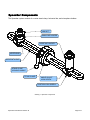
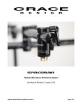
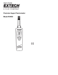
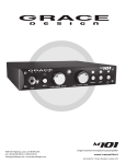
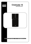
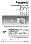
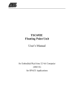
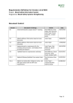
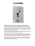
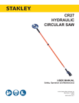
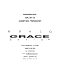
Spacebar Precision Microphone Positioner
User Manual, Revision B, December 2, 2009
Table of Contents
Spacebar Components...............................................................................................................2
Setup Procedure.........................................................................................................................4
Changing the mic holder height..................................................................................................5
Changing the horizontal bar length.............................................................................................5
Center mount bridge SB-CMB (optional)....................................................................................6
Exploded parts diagrams............................................................................................................7
Revision History..........................................................................................................................9
The Grace Design Spacebar microphone positioner allows for precise and repeatable setting of
microphone capsule spacing, angle of incidence, and rotation around the x axis. With precision scales
for angle and distance engraved on the Spacebar components, it becomes easy to make perfectly
repeatable stereo microphone setups.
As well as being able to precisely set microphones in standard stereo configurations (i.e. XY, ORTF,
NOS, and AB 50cm), the Spacebar allows for exact settings through the entire continuum of angle and
spacing. This allows the user to adjust the stereo microphone array and tailor the pickup field to suit
virtually any recording environment.
We highly recommend The Stereophonic Zoom by Michael Williams, a technical paper that provides
detailed information on the relationship between angle of incidence, capsule spacing, and the effective
angle of the recorded sound field. It is a very useful reference that can greatly increase the flexibility
of your stereo microphone techniques. The Stereophonic Zoom can be downloaded from:
http://www.microphone-data.com/pdfs/Stereo%20zoom.pdf
The Spacebar system is precision fabricated from machined aircraft aluminum, brass, and stainless
steel. If properly cared for it should last a lifetime.
In the event that you encounter any technical or operational difficulties with this or any Grace Design
product, please feel free to contact us at 303-443-7454. Our office hours are from 9 to 5, Monday
through Friday, MST. Or you can e-mail any questions to: [email protected]
Spacebar User Manual Revision B
Page 1of 9
Spacebar Components
The Spacebar system consists of a center stand clamp, horizontal bar, and microphone holders.
JAM NUT
SMALL MIC HOLDER
LARGE MIC HOLDER
KEYED RING
HORIZONTAL BAR
STAND CLAMP
LOCKING HANDLE
STAND CLAMP
ANGLE ADJUST
LOCK SCREW
POSITION LOCK SCREW
Drawing 1: Spacebar Components
Spacebar User Manual Revision B
Page 2of 9
1. The horizontal bar comes in two sizes: 30cm for the SB-30 and 66cm for the SB-66. The 30cm
and 66cm horizontal barS are interchangeable in the field. The maximum microphone holder
spacing is as follows:
Model
Minimum spacing
Maximum spacing
SB-30
7cm (2.75”)
26cm (10.2”)
SB-66
7cm (2.75”)
61cm (24”)
2. The stand clamp mounts on a standard 5/8”-27 microphone stand thread. Note: the threaded
section of the microphone stand should not be longer than 7/16”. Threading the stand further
than 7/16” into the stand clamp can cause the horizontal bar to bind and not rotate freely.
3. The microphone holders are secured to the horizontal bar by the position lock nuts. Loosening
these nuts will allow the microphone holders to slide side to side for adjusting the microphone
spacing. The horizontal position can be adjusted with 5mm precision by using the ruler on the
front of the horizontal bar. Note that these rulers are for reference as the actual capsule
spacing will need to be determined with a measuring tape or ruler. The SB-30 and SB-66 are
both supplied with two microphone holder assemblies and an additional tall microphone holder.
The taller microphone holder body can be used to raise one microphone to avoid interference if
the mic spacing requires that the microphone bodies overlap. See Changing the mic holder
height later in this manual. Additional microphone holders can be purchased if more than two
microphones are to be mounted to the Spacebar.
Drawing 2: SB-66 with multiple mic holders
4. When the position lock nuts are loose the microphone angle can be adjusted by loosening the
angle adjust locking screws. The angle of incidence can be adjusted with 5° precision by using
the angle scale on the front of the microphone holder.
Spacebar User Manual Revision B
Page 3of 9
Drawing 3: Adjusting the position of the clamp handle
5. The vertical angle of the microphones can be adjusted by loosening the clamp handle and then
rotating the horizontal bar to the desired angle. For reference there is a +/-90° scale on the
side of the stand clamp. The stand clamp locking handle is adjustable and is set from the
factory to provide a good clamping force with the handle pointing downward. To adjust the
angle of the handle pull the handle back from the stand clamp while rotating. When released,
the handle will snap back and engage in the new position.
Setup Procedure
1. On the mic holder assemblies loosen the position locking nut and the angle locking screw and
set the angle to 0°. Tighten both again.
2. Thread on the microphone clips for your desired microphones but do not tighten all the way.
Put the microphones in the clips and while looking down on the Spacebar from above point the
mics so that they are pointing straight forward and are perpendicular to the horizontal bar.
While holding the microphone in this position turn the jam nut counter clockwise until the clip is
securely locked.
Spacebar User Manual Revision B
Page 4of 9
90
°
90°
Drawing 4: Microphone alignment, top view
3. Unlock the position locking nut and the angle lock screw and rotate the clip to the desired
angle of incidence. Re-lock the angle lock screw.
4. Mount the microphones and, using a tape measure or ruler, adjust the spacing between
capsules.
5. Lock the position locking nuts.
Changing the mic holder height
1. To change between the standard height mic holder and the tall mic holder loosen and remove
the Position Lock Nut while while holding the microphone holder assembly so that it does not
fall.
2. Loosen the Angle Lock Screw and remove the microphone holder body from the keyed ring.
3. Insert the desired microphone holder body into the keyed ring and tighten the Angle Lock
Screw.
4. Place the microphone holder assembly into the slot on the horizontal bar and install the
Position Lock Screw to secure the assembly.
Changing the horizontal bar length
1. Refer to the exploded parts diagram at the end of this manual.
2. To remove the horizontal bar loosen the 8-32 set screw (H407) with a 5/64” hex wrench. Turn
the set screw counter clock wise about 4 turns.
3. Twist the clamp handle counter-clockwise to loosen its grip and slide the horizontal bar out of
the stand clamp.
4. Insert the desired horizontal bar into the stand clamp and center it but do not tighten the clamp
yet.
5. Tighten the set screw with the hex wrench until the screw stops then loosen the set screw by ¼
Spacebar User Manual Revision B
Page 5of 9
turn. The horizontal bar should rotate freely but not slide out of the stand clamp.
Center mount bridge SB-CMB (optional)
1. The SB-CMB center mount brigde option allows for the mounting of a center microphone. The
SB-CMB mounts to the horizontal bar such that the center mic will follow any z-axis
adjustments made to the Spacebar. Either the 30cm or 66cm bar can be used.
2. The SB-CMB is mounted to the horizontal bar with two 1/4-20 x 1-3/4” socket head cap
screws. Use the 3/16” hex wrench included with the SB-CMB kit to tighten these screws.
3. The 24mm thumb nut clamps the mic holder bar in place. Loosening this nut allows the mic
holder front to back position to be adjusted from 3cm to 13.5cm.
24mm THUMB NUT
1/4-20 x 1-3/4”
SOCKET HEAD
CAP SCREW
Drawing 5: SB-CMB Assembly
Spacebar User Manual Revision B
Page 6of 9
Exploded parts diagram: Spacebar SB-30
13
15
12
15
11
13
6
12
2
11
8
14
4
5
3
7
13
2
10
9
1
1
2
3
4
5
6
7
8
9
10
11
12
13
14
15
E401
E406
E404
E403
H432
H510
E402
E405
E400
H407
H512
H520
H514
H436
H459
H515
30cm Microphone Bar
66cm Mic Bar (optional)
KEYED RING
Mic Holder Large
10-32 x 1/4" SK CP SS
Knob Black 5/8"
Mic Holder Small
24mm Nut 10-32 Thread
Round Stand Clamp
8-32 x 3/8" Set Screw Pilot Point
Adjustable Handle 10-32 x .78" stud
Round Pin 1/16" x .3"
5/8-27 Threaded Boss
10-32 x 7/8" FL SC SS
#10 Flat Washer Bronze
5/8-27 24mm Nut
Spacebar User Manual Revision B
1
1
1
2
1
2
2
1
2
1
1
1
2
2
4
1
2
5
7
4
13
Page 7of 9
Exploded parts diagram: SB-CMB
7
4
5
3
2
1
6
9
8
ITEM NO.
1
2
3
4
5
6
7
8
9
Spacebar User Manual Revision B
Grace
Part #
E427
E426
H514
H515
E405
H494
H446
H489
H493
DESCRIPTION
Center Mount Bridge
Center Mount Mic Holder
5/8-27 Threaded Boss
5/8-27 24mm Nut
24mm Nut 10-32 Thread
1/4" X 1" Spacer, .252" ID, 1/2" OD, Black Aluminum
10-32 x 3/4" Flat Socket Head Cap Screw
1/4-20 X 1-3/4" Socket Head Cap Screw Stainless Steel
1/4-20 Flat Washer Stainless Steel
QTY.
1
1
1
1
1
2
2
2
2
Page 8of 9
Revision History
Rev.
Description
Date
A
Initial release
01/30/09
MBG
B
Changed wording in “Changing horizontal bar length”
Added SB-CMB instructions.
10/03/09
MBG
Spacebar User Manual Revision B
Initials
Page 9of 9