1
Low Voltage Products
Masterpact NT06-16 IEC
User manual
User manual for
Masterpact NT06-16 IEC
circuit breakers
Discovering Masterpact
Using Masterpact
2
8
Understanding the controls and indications
Charging the circuit breaker
Closing the circuit breaker
Opening the circuit breaker
Resetting after a fault trip
Locking the controls
8
9
10
11
12
13
Using the Masterpact drawout chassis
16
Identifying the circuit breaker positions
Racking
Matching a Masterpact circuit breaker with its chassis
Locking the switchboard door
Locking the circuit breaker in position
Locking the safety shutters
16
17
20
21
22
25
Identifying the electrical auxiliaries
26
Identification of the connection terminals
Operation
Electrical diagrams
26
27
28
Discovering Masterpact's accessories
30
Micrologic control units
Indication contacts
Auxiliaries for remote operation
Device mechanical accessories
Chassis accessories
30
31
33
36
38
Inspecting and testing before use
40
Initial tests
What to do when the circuit breaker trips
40
41
Maintaining Masterpact performance
42
Recommended maintenance program
Maintenance operations
Ordering replacement parts
Troubleshooting and solutions
42
43
44
46
Checking Masterpact operating conditions
48
1
Masterpact NT06-16 IEC
E51299A
Discovering Masterpact
E60055A
Rating plate
2
Masterpact NT06-16 IEC
Schneider Electric
3
Masterpact NT06-16 IEC
Schneider Electric
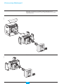
Discovering Masterpact
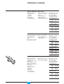
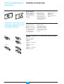
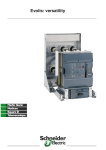
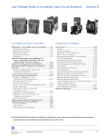
Masterpact circuit breakers are available in drawout and fixed versions.
The drawout version is mounted on a chassis and the fixed version is installed
using fixing brackets.
E51321A
Drawout version
ET
RES
E51322A
Fixed version
ET
RES
4
Masterpact NT06-16 IEC
Schneider Electric
E60056A
Chassis
5
Masterpact NT06-16 IEC
Schneider Electric
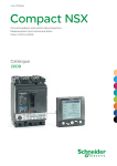
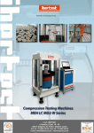
Discovering Masterpact
E60057A
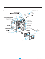
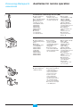
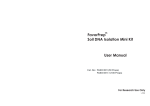
Drawout circuit breaker / switch-disconnector
XF closing release
Arc chute
MX/1 opening release
MX/2 opening release or MN
undervoltage release
OF "ON/OFF" indication contacts
Terminals for control unit, fault
indication contacts, control
auxiliaries and auxiliary contacts
PF "ready to close" contact
SDE/1 "fault-trip" indication contact
Operating-mechanism
charging handle
Carrying grip
MCH gear motor for
electrical charging of the
operating mechanism
Keylock for locking in open position
BPFE electrical closing pushbutton
BPFE electrical closing pushbutton
Side plate for
drawout device
Padlock for locking
in open position
SDE/2 "fault-trip" indication contact
or Res electrical remote reset
Closing pushbutton
Opening pushbutton
Operation counter
Control unit
6
Masterpact NT06-16 IEC
Schneider Electric
E60058A
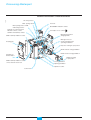
Fixed circuit breaker / switch-disconnector
Control auxiliary terminals
Arc chute
MX/1 opening release
MX/2 opening release or MN undervoltage
release
Auxiliary contact terminals
OF "ON/OFF" indication contacts
Terminals for control unit and fault
indication contacts
PF "ready to close" contact
Operating-mechanism
charging handle
SDE/1 "fault-trip" indication contact
MCH gear motor for
electrical charging of the
operating mechanism
Carrying grip
Keylock for locking
in open position
BPFE electrical closing pushbutton
BPFE electrical closing pushbutton
Side plate for fixed
device
Padlock for locking
in open position
Closing pushbutton
SDE/2 "fault-trip" indication contact
or Res electrical remote reset
Opening pushbutton
Operation counter
Control unit
E60059A
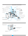
Front
Trip indication button used
to reset before closing
Rating plate
T
RESE
Locking by padlock, lead-seal cover
or screws for pushbuttons
"Springs charged" and "Ready
to close" indicator
Indicator for position of the
main contacts
7
Masterpact NT06-16 IEC
Schneider Electric
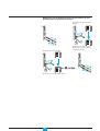
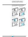
Understanding the controls and
indications
E51344A
Using Masterpact
Circuit breaker closed and
discharged
E51488A
E51489A
Circuit breaker open and
discharged
O
I
h ON
Pus
O
Circuit breaker open,
charged and not "ready
to close"
I
Pus
h ON
F
h OF
Pus
Circuit breaker closed and
charged
E51491A
E51490A
h ON
F
h OF
Pus
F
h OF
Pus
O
I
Pus
O
I
Pus
h ON
F
h OF
Pus
E51492A
Circuit breaker open,
charged and "ready to
close"
O
I
Pus
h ON
F
h OF
Pus
8
Masterpact NT06-16 IEC
Schneider Electric
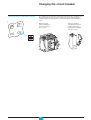
Charging the circuit breaker
The springs in the circuit breaker operating mechanism must be charged to store
the energy required to close the main contacts. The springs may be charged
manually using the charging handle or automatically by the optional MCH gear
motor.
E60072A
The charge status is indicated as follows.
h ON
E51347A
F
h OF
Pus
Automatic charging.
If the MCH gear motor is
installed, the spring is
automatically recharged
after each closing.
E46790A
O
Manual charging.
Pull the handle down
seven times until you
hear a "clack".
I
Pus
or
MERLIN
9
Masterpact NT06-16 IEC
GERIN
Schneider Electric
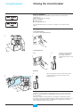
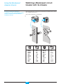
Closing the circuit breaker
Device "ready to close"
Closing conditions
E51291A
Using Masterpact
Closing (i.e. turning the circuit ON) is possible only if the circuit breaker is
"ready to close".
The prerequisites are the following:
b device open (OFF)
b springs charged
b no opening order present.
E51292A
Device not "ready to close"
The circuit breaker will not close unless it is "ready to close" when the order
is given.
Closing the circuit breaker
E51493A
E60047A
Locally (mechanical)
Press the mechanical ON pushbutton.
Pu
O
OFF
Push
Locally (electrical)
XF
E60049A
E51294A
BPFE
Press the electrical closing
pushbutton. By adding an
XF closing release, the
circuit breaker can be closed
locally.
Remotely
E51294A
E60048A
XF
When connected to a remote control panel, the XF
closing release can be used to close the circuit
breaker remotely.
Anti-pumping function
The purpose of the mechanical anti-pumping function is to ensure that a circuit
breaker receiving simultaneous opening and closing orders does not open and
close indefinitely.
If there is a continuous closing order, after opening the circuit breaker remains
open until the closing order is discontinued. A new closing order is required to close
the circuit breaker. A new order is not required if the closing release is wired in
series with the PF "ready to close" contact.
10
Masterpact NT06-16 IEC
Schneider Electric
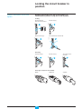
Opening the circuit breaker
E51499A
E60047A
Locally
Press the OFF pushbutton.
I
ON
Push
E60048A
Push
Remotely
Use one of the following solutions:
b one or two MX opening releases (MX1 and MX2)
b one MN undervoltage release
b one MN undervoltage release with a delay unit.
When connected to a remote control panel, these releases can be used to open
the circuit breaker remotely.
Delay unit
E51296A
E51294A
MX1, MX2, MN
1
2
3
4 5
6
S
3 6
0.5
30 V
100/1C
AC/D
1
11
Masterpact NT06-16 IEC
2
1
1.5
3
MN
r de R
UV
dateu
Retardelay for
Time
MN
UVR
10 12
3
Schneider Electric
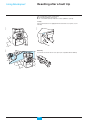
Resetting after a fault trip
Using Masterpact
The circuit breaker signals a fault trip by:
b a mechanical indicator on the front
b one or two SDE "fault-trip" indication contacts (SDE/2 is optional).
E51349A
E60047A
Locally
If the circuit breaker is not equipped with the automatic reset option, reset it
manually.
E60048A
ET
RES
E60050A
Remotely
Use the Res electrical remote reset option (not compatible with an SDE/2).
12
Masterpact NT06-16 IEC
Schneider Electric
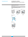
Locking the controls
Disabling circuit-breaker local closing
and opening
Pushbutton locking using a padlock
(shackle diameter 5 to 8 mm), a lead seal or screws.
push
Locking
Close the covers.
ON
OFF
O
I
Push OFF
Push ON
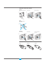
E60018A
E60017A
O OFF
Unlocking
Remove the padlock,
lead seal or screws.
The pushbuttons are no
longer locked.
Lift the covers and swing
them down.
E60019A
E60018A
E60016A
Insert the padlock
shackle, lead seal or
screws.
ed
harg
disc
13
Screws.
Masterpact NT06-16 IEC
E60020A
E60013A
I
O
push
E60015A
Lead seal.
E60014A
Padlock.
O
I
Push OFF
Push ON
Schneider Electric
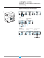
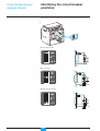
Locking the controls
Disabling local and remote closing
Using Masterpact
Combination of locking systems
To disable local and remote circuit-breaker closing, use as needed one to three
padlocks or a keylock.
Install one to three padlocks
(maximum shackle diameter 5 to 8 mm)
Insert the padlock
shackle.
E51362A
I
Pull out the tab.
E51350A
E51499A
Locking
Open the circuit breaker.
ON
Push
Push
E51446A
Check
The closing control is
inoperative.
E51447A
Unlocking
Remove the padlock.
14
Masterpact NT06-16 IEC
Schneider Electric
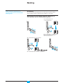
Locking the controls with a keylock
Remove the key.
E51449A
I
Turn the key.
E51448A
E51499A
Locking
Open the circuit breaker.
ON
Push
Push
E51446A
Check
The closing control is
inoperative.
The key cannot be
removed.
E60010A
Turn the key.
E60009A
E60008A
Unlocking
Insert the key.
Three types of keylocks are available
RONIS
15
Masterpact NT06-16 IEC
CASTELL
E51271A
E51270A
E51269A
PROFALUX
Schneider Electric
Identifying the circuit breaker
positions
Using the Masterpact
drawout chassis
E51451A
The indicator on the front signals the position of the circuit breaker in the chassis.
E51314A
E51453A
b "connected" position
Test
E51454A
E60073A
b "test" position
Test
10.9 mm
E60074A
E51455A
b "disconnected" position
Test
32.2 mm
16
Masterpact NT06-16 IEC
Schneider Electric
Racking
Prerequisites
These operations require that all
chassis-locking functions be disabled
(see page 22).
To connect and disconnect Masterpact, the crank must be used. The locking
systems, padlocks and the racking interlock all inhibit use of the crank.
Withdrawing the circuit breaker from the "connected" to
"test" position, then to "disconnected" position
DB110365
The circuit breaker is in
"connected" position.
The circuit breaker is in "test" position.
Remove the crank or continue to
"disconnected" position.
The circuit breaker is in "test" position.
The circuit breaker is in "disconnected" position.
17
Masterpact NT06-16 IEC
Schneider Electric
Using the Masterpact
drawout chassis
Racking
For complete information on Masterpact
handling and mounting, see the installation
manual(s).
Removing the rails
1
E51459A
Press the release tabs to push
the rails in.
E51458A
Before mounting the circuit breaker, make
sure it matches the chassis.
Press the release tabs
and pull the rails out.
2
3
Inserting Masterpact
Position the circuit breaker on the rails.
Check that it rests on all four supports.
E51499A
E51460A
Open the circuit breaker
(in any case, it opens
automatically during
connection).
I
ON
Push
Push
E60034A
E51461A
Push the circuit breaker into the chassis, taking care not to push on the control unit.
I
O
push
push
ON
OFF
rged
discha
O OFF
I ON
OOFF
push
push
rged
discha
O OFF
E60033A
If you cannot insert the circuit breaker in the
chassis, check that the mismatch protection
on the chassis corresponds to that on the
circuit breaker.
I
O
push
push
ON
OFF
rged
discha
O OFF
18
Masterpact NT06-16 IEC
Schneider Electric
Racking the circuit breaker from the "disconnected" to "test"
position, then to "connected" position
DB110366
The device is in "disconnected"
position.
The device is in "test" position.
The device is in "test" position.
Remove the crank or continue to
"connected" position.
The device is in "connected" position.
19
Masterpact NT06-16 IEC
Schneider Electric
Using the Masterpact
drawout chassis
Matching a Masterpact circuit
breaker with its chassis
To set up a mismatch-prevention
combination for the circuit breaker and the
chassis, see the mismatch-prevention
installation manual.
The mismatch protection ensures that a circuit breaker is installed only in a chassis
with compatible characteristics.
E60052A
The possible combinations are listed below.
A
1
B
2
C
3
4
5
D
E
ABC
ABD
ABE
AB
ACD
ACE
AC
ADE
AD
AE
20
45
35
34
345
25
24
245
23
235
234
Masterpact NT06-16 IEC
BCD
BCE
BC
BDE
BD
BE
CDE
CD
CE
DE
15
14
145
13
135
134
12
125
124
123
Schneider Electric
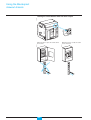
Locking the switchboard door
E51464A
The locking device is installed on the left or right-hand side of the chassis.
b when the circuit breaker is in "connected" or "test" position, the latch is lowered
and the door is locked
b when the circuit breaker is in "disconnected" position, the latch is raised and the
door is unlocked.
O
OFF
push
O OFF
I ON
OOFF
push
push
arged
disch
O OFF
Disabling door opening
Put the Masterpact in
"test" or "connected"
position.
The door is locked.
E51467A
E51466A
E51465A
Close the door.
Enabling door opening
The door is unlocked.
E51468A
E51469A
Put the Masterpact in
"disconnected" position.
I
O
push
push
ON
OFF
discharged
O OFF
21
Masterpact NT06-16 IEC
Schneider Electric
Using the Masterpact
drawout chassis
Locking the circuit breaker in
position
Padlocks and keylocks may be used
together.
Combination of locking systems
To disable connection of the circuit breaker in "disconnected" position in the
chassis, use as needed:
b one to three padlocks
b one or two keylocks
b a combination of the two locking systems.
If specified when ordering the chassis, this
locking function may be adapted to operate
in all positions ("connected", "test" and
"disconnected"), instead of in
"disconnected" position alone.
Disabling connection when the circuit breaker is in
"disconnected" position, using one to three padlocks
(maximum shackle diameter 5 to 8 mm)
Locking
Pull out the tab.
E51470A
E60022A
Circuit breaker in "disconnected"
position.
1
2
Test
3
The crank cannot be inserted.
E51472A
E51471A
Insert the shackle
(max. diameter 5 to 8 mm)
of the padlock(s).
4
Unlocking
1
Release the tab.
E51474A
E51473A
Remove the padlock(s).
2
E51475A
The crank can be inserted.
3
22
Masterpact NT06-16 IEC
Schneider Electric
Locking the circuit breaker in
position
Disabling connection when the circuit breaker is in
"disconnected" position, using one or two keylocks.
Padlocks and keylocks may be used
together.
Turn the key(s).
E51476A
E60053A
Locking
Circuit breaker in
"disconnected" position.
1
22
Test
3
3
The crank cannot be inserted.
E60023A
E51477A
Remove the key(s).
44
Unlocking
2
The crank can be
inserted.
E51487A
1
Turn the key(s).
E51479A
E51478A
Insert the key(s).
3
Three types of keylocks are available
23
Masterpact NT06-16 IEC
CASTELL
E51271A
PROFALUX
E51269A
E51270A
RONIS
Schneider Electric
Using the Masterpact
drawout chassis
E60024A
Locking the circuit breaker when the door is open
I
O
push
push
ON
OFF
ed
harg
disc
O OFF
When the door is closed, the crank
can be inserted.
E51496A
E51495A
When the door is open, the crank cannot
be inserted.
I
O
push
push
ON
OFF
discharged
O OFF
24
Masterpact NT06-16 IEC
Schneider Electric
Locking the safety shutters
Padlocking inside the chassis
Four locking possibilities: using one or two padlocks
(maximum shackle diameter 5 to 8 mm) for each shutter
Top shutter not locked.
Bottom shutter locked.
Top shutter locked.
Bottom shutter not locked.
Top and bottom shutters locked.
E60026A
E60025A
Top and bottom shutters not
locked.
25
Masterpact NT06-16 IEC
Schneider Electric
Identification of the connection
terminals
Layout of terminal blocks
E60044A
Identifying the electrical
auxiliaries
CD2
824
822
821
CD1
814
812
811
Com UC1 UC2
E5 E6 Z5 M1 M2 M3
E3 E4 Z3 Z4 T3 T4
E1 E2 Z1 Z2 T1 T2
UC3
F2
VN
F1
M2C/UC4 SDE2/Res SDE1 MN/MX2
84 D2/C12
184/K2
484/V3
82
C13
182
474/V2
81 D1/C11
181/K1
471/V1
MX1
C2
C3
C1
XF
A2
A3
A1
PF MCH
254 B2
252 B3
251 B1
M2C/UC4 SDE2/Res SDE1 MN/MX2
84 D2/C12
184/K2
484/V3
82
C13
182
474/V2
81 D1/C11
181/K1
471/V1
MX1
C2
C3
C1
XF
A2
A3
A1
PF MCH
254 B2
252 B3
251 B1
OF4 OF3 OF2 OF1
44
34
24
14
42
32
22 12
41
31
21
11
CE3
334
332
331
CE2
324
322
321
CE1
314
312
311
CT1
914
912
911
Com UC1 UC2
E5 E6 Z5 M1 M2 M3
E3 E4 Z3 Z4 T3 T4
E1 E2 Z1 Z2 T1 T2
UC3
F2
VN
F1
OF4 OF3 OF2 OF1
24
14
44
34
42
22 12
32
21
11
41
31
26
Masterpact NT06-16 IEC
Schneider Electric
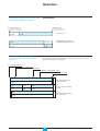
Operation
E60060A
The ON/OFF indication contacts signal the
status of the device main contacts.
completely closed
closed
completely open
main contacts
open
open
closed
closed
open
The carriage switches indicate the
"connected", "test" and "disconnected"
positions.
E60061A
Circuit breaker
OF: ON/OFF (closed/open)
indication changeover contacts
Chassis
For information on the separation distance of the main circuits in the "test" and
"disconnected" positions, see page 16.
completely connected
separation of the main circuits
test position
separation of the auxiliary circuits
completely disconnected
open
CE: connected-position
carriage switch
closed
open
closed
open
closed
open
closed
CT: test-position carriage
switch
open
CD: disconnected-position
carriage switch
closed
27
Masterpact NT06-16 IEC
Schneider Electric
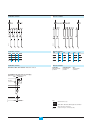
Electrical diagrams
Fixed and drawout devices
Identifying the electrical
auxiliaries
The diagram is shown with circuits
de-energised, all devices open, connected
and charged and relays in normal position.
Control unit
Remote operation
DB101401
Power
Remote operation
Control unit
Com UC1
UC2
UC3
UC4 / M2C / M6C
SDE2 / Res
E5 E6 Z5 M1 M2 M3
F2+
V3
/ 484
/ Q3
184
E3 E4 Z3 Z4 T3 T4
VN
V2
/ 474
/ Q2
182
E1 E2 Z1 Z2 T1 T2
F1 –
V1
/ 471
/ Q1
181
/
K2
SDE1
84
MN / MX2
D2
/ C12
82
/
K1
81
D1
/ C11
A
P
H
Control unit
Remote operation
c
c
c
Com: E1-E6 communication
c
c
c
UC1: Z1-Z5 zone selective interlocking;
Z1 = ZSI OUT SOURCE
Z2 = ZSI OUT; Z3 = ZSI IN SOURCE
Z4 = ZSI IN ST (short time)
Z5 = ZSI IN GF (earth fault)
M1 = Vigi module input (Micrologic 7)
SDE2: Fault-trip indication contact
or
Res: Remote reset
c
c
c
c
c
c
c
c
c
UC2: T1, T2, T3, T4 = external neutral;
M2, M3 = Vigi module input
(Micrologic 7)
c
c
c
c
c
UC3: F2+, F1– external 24 V DC power
supply
VN external voltage connector
c
c
UC4: V1, V2, V3 optional external voltage
connector
or
c
c
c
c
M2C: 2 programmable contacts (internal
relay); ext. 24 V DC power supply
required
or
MX1
XF
PF
MCH
C2
A2
254
B2
C3
A3
252
B3
C1
A1
251
B1
SDE1: Fault-trip indication contact (supplied as standard)
MN: Undervoltage release
or
MX2: Shunt release
MX1: Shunt release (standard or communicating)
XF:
Closing release (standard or communicating)
PF:
"Ready to close" contact
MCH: Gear motor (*)
Note:
When communicating MX or XF releases are used, the third wire
(C3, A3) must be connected even if the communications module is
not installed.
M6C: 6 programmable contacts (external
relay); ext. 24 V DC power supply
required.
A: Digital ammeter
P: A + power meter + programmable protection
H: P + harmonics
28
Masterpact NT06-16 IEC
Schneider Electric
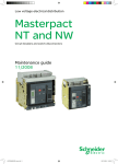
Chassis contacts
DB101406
DB101407
Indication contacts
Indication contacts
Chassis contacts
OF4
OF3
OF2
OF1
CD2
44
34
24
14
42
32
22
12
41
31
21
11
Indication contacts
OF4 / OF3 / OF2 / OF1: ON/OFF indication contacts
CD1
CE3
CE2
CE1
CT1
824
814
334
324
314
914
822
812
332
322
312
912
821
811
331
321
311
911
Chassis contacts
CD2-CD1:
CE3-CE2-CE1:
DisconnectedConnectedposition
position
CT1:
Test-position
contacts
(*) 440/480 V AC gear motor for charging
(380 V motor + additional resistor)
CN1
- 440/480 V
9
440/480 V
"charged LED"
11
R
B3 B2
MCH
380V
CH
E60075A
B1
CN2
Key:
- 440/480 V
Drawout device only
XXX
SDE1, OF1, OF2, OF3, OF4 supplied as standard
Interconnected connections
(only one wire per connection point)
29
Masterpact NT06-16 IEC
Schneider Electric
Micrologic control units
For more in-depth information, see the
control-unit user manual.
Micrologic control units
E51329A
E46108A
Discovering Masterpact’s
accessories
b standard equipment,
one per device
b long-time rating plug
and connectors not
included, see below:
Micrologic 2.0
Micrologic 5.0
Micrologic 2.0A
Micrologic 5.0A
Micrologic 6.0A
Micrologic 7.0A
Micrologic 5.0P
Micrologic 6.0P
Micrologic 7.0P
Micrologic 5.0H
Micrologic 6.0H
Micrologic 7.0H
b connectors for A, P, H:
v for fixed device
v for drawout device.
b depending on the
model, control units offer
in addition:
v fault indications
v measurement of
electrical parameters
(current, voltage, power,
etc.)
v harmonic analysis
v communication.
Long-time rating plugs
b standard equipment,
one per control unit
b setting options:
v standard 0.4 to 1 x Ir
setting
v low 0.4 to 0.8 x Ir
setting
v high 0.8 to 1 x Ir
setting
v off (no long-time
protection).
b the plugs determine
the setting range for the
long-time protection.
M2C and M6C programmable contacts
b optional equipment,
used with Micrologic P
and H control units
b connectors not
included, see below:
v 2 M2C contacts
v 6 M6C contacts
b connectors:
v for fixed device
v for drawout device.
30
b contacts can be
programmed using the
keypad on the control
unit or via the COM
option
b they indicate:
v the type of fault
v instantaneous or
delayed threshold
overruns.
Masterpact NT06-16 IEC
b M2C: 2 contacts
(5 A - 240 V)
b M6C: 6 contacts
(5 A - 240 V).
b permissible load on
each of the M6C relay
outputs at cos ϕ = 0.7
v 240 V AC: 5 A
v 380 V AC: 3 A
v 24 V DC: 1.8 A
v 48 V DC: 1.5 A
v 125 V DC: 0.4 A
v 250 V DC: 0.15 A
b M2C: 24 V DC ± 5 %
power from control unit
b M6C: 24 V DC ±5 %
external supply
b maximum
consumption: 100 mA.
Schneider Electric
Indication contacts
ON/OFF indication contacts (OF)
b standard equipment,
4 OF per device
v standard
v low level
b connectors:
v for fixed device
v for drawout device.
b OF contacts indicate
the position of the main
contacts
b they trip when the
minimum isolation
distance between the
main contacts is reached.
b 4 changeover contacts
b breaking capacity at
cos ϕ = 0.3 (AC12 /
DC12 as per 947-5-1)
v standard, minimum
current 10 mA / 24 V
V AC 240/380 6 A (rms)
480
6 A (rms)
690
6 A (rms)
V DC 24/48
2.5
125
0.5
250
0.3
v low level, minimum
current 1 mA / 4 V
V AC 24/48
5 A (rms)
240
5 A (rms)
380
5 A (rms)
V DC 24/48
5 / 2.5 A
125
0.5 A
250
0.3 A
"Fault-trip" indication contact (SDE/1)
E60054A
b standard equipment on
circuit breakers, one
SDE/1 contact per
device
b not available for switchdisconnector versions.
b the contact provides a
remote indication of
device opening due to an
electrical fault.
b changeover contact
b breaking capacity at
cos ϕ = 0.3 (AC12 /
DC12 as per 947-5-1)
v standard, minimum
current 10 mA / 24 V
V AC 240/380 5 A (rms)
480
5 A (rms)
690
3 A (rms)
V DC 24/48
3A
125
0.3 A
250
0.15 A
v low level, minimum
current 1 mA / 4 V
V AC 24/48
3 A (rms)
240
3 A (rms)
380
3 A (rms)
V DC 24/48
3A
125
0.3 A
250
0.15 A
Additional "fault-trip" indication contact (SDE/2)
b optional equipment for
circuit breakers, one
additional SDE/2 contact
per device
b not available for switchdisconnector versions
b not compatible with the
Res option
b connectors not
included, see below:
v standard
v low level
b connectors:
v for fixed device
v for drawout device.
31
b the contact remotely
indicates device opening
due to an electrical fault.
Masterpact NT06-16 IEC
b changeover contact
b breaking capacity at
cos ϕ = 0.3 (AC12 /
DC12 as per 947-5-1)
v standard, minimum
current 10 mA / 24 V
V AC 240/380 5 A (rms)
480
5 A (rms)
690
3 A (rms)
V DC 24/48
3A
125
0.3 A
250
0.15 A
v low level, minimum
current 1 mA / 4 V
V AC 24/48
3 A (rms)
240
3 A (rms)
380
3 A (rms)
V DC 24/48
3A
125
0.3 A
250
0.15 A
Schneider Electric
E60050A
Discovering Masterpact’s
accessories
Indication contacts
Electrical reset after fault trip (Res)
b optional equipment,
one Res per device
b not compatible with the
SDE/2 option
b connectors not
included, see below:
v 110/130 V AC
v 220/240 V AC
b connectors:
v for fixed device
v for drawout device.
b the contact remotely
resets the device
following tripping due to
an electrical fault.
"Springs charged" limit switch contact (CH)
E51332A
b equipment included
with MCH gear motor,
one CH contact per
device.
b the contact indicates
the "charged" status of
the operating mechanism
(springs charged).
b changeover contact
b breaking capacity 50/
60 Hz for AC power
(AC12 / DC12 as per
947-5-1):
V AC 240
10A(rms)
380
6 A (rms)
480
6 A (rms)
690
3 A (rms)
V DC 24/48
3A
125
0.5 A
250
0.25 A
"Ready to close" contact (PF)
b optional equipment,
one PF contact per
device
b connectors not
included, see below:
v standard
v low level
b connectors:
v for fixed device
v for drawout device.
32
b the contact indicates
that the device may be
closed because all the
following are valid:
v circuit breaker is open
v spring mechanism is
charged
v a maintained closing
order is not present
v a maintained opening
order is not present.
Masterpact NT06-16 IEC
b changeover contact
b breaking capacity at
cos ϕ = 0.3 (AC12 /
DC12 as per 947-5-1)
v standard, minimum
current 10 mA / 24 V
V AC 240/380 5 A (rms)
480
5 A (rms)
690
3 A (rms)
V DC 24/48
3A
125
0.3 A
250
0.15 A
v low level, minimum
current 1 mA / 4 V
V AC 24/48
3 A (rms)
240
3 A (rms)
380
3 A (rms)
V DC 24/48
3A
125
0.3 A
250
0.15 A
Schneider Electric
E51294A
E46790A
Auxiliaries for remote operation
Gear motor (MCH)
b optional equipment,
one MCH gear motor per
device
b connectors not
included, see below:
v AC 50 / 60 Hz:
48/60
100/130
200/240
277/415
440/480
v DC
24/30
48/60
100/125
200/250
b connectors:
v for fixed device
v for drawout device.
b the gear motor
automatically charges the
spring mechanism.
b power supply:
v V AC 50/60 Hz: 48/60
100/130 - 200/240 - 277
400/440 - 480
v V DC: 24/30 - 48/60
100/125 - 200/250
b operating threshold:
0.85 to 1.1 Un
b consumption:
180 VA or W
b inrush current:
2 to 3 In for 0.1 second
b charging time:
3 seconds max.
b operating rate:
maximum 3 cycles per
minute
b CH contact: see page
32.
Opening releases MX/1 and MX/2, closing release XF
b optional equipment, 1
or 2 MX releases per
device, 1 XF per device
b the function (MX or XF)
is determined by where
the coil is installed
b connectors not
included, see below
V AC 50/60 Hz, V DC:
v standard version:
12 DC
24/30 AC/DC
48/60 AC/DC
100/130 AC/DC
200/250 AC/DC
240/277 AC
380/480 AC
v communicating version
(with COM option):
12 DC
24/30 AC/DC
48/60 AC/DC
100/130 AC/DC
200/250 AC/DC
240/277 AC
380/480 AC
b connectors:
v for fixed device
v for drawout device.
33
b the MX release
instantaneously opens
the circuit breaker when
energised
b the XF release
instantaneously closes
the circuit breaker when
energised, if the device is
"ready to close".
Masterpact NT06-16 IEC
b power supply:
v V AC 50 / 60 Hz:
24 48 - 100/130 - 200/
250 240/277 - 380/480
v V DC: 12 - 24/30
48/60 - 100/130
200/250
b operating threshold:
v XF: 0.85 to 1.1 Un
v MX: 0.7 to 1.1 Un
b consumption:
v pick-up: 200 VA or W
(80 ms)
v hold: 4.5 VA or W
b circuit-breaker
response time at Un:
v XF: 55 ms ± 10
v MX: 50 ms ± 10.
Schneider Electric
E51294A
Discovering Masterpact’s
accessories
Instantaneous undervoltage releases (MN)
E51296A
b optional equipment,
1 MN per device
b not compatible with the
MX/2 opening release
b connectors not
included, see below
V AC 50/60 Hz, V DC:
24/30 AC/DC
48/60 AC/DC
100/130 AC/D
200/250 AC/DC
380/480 AC
b connectors:
v for fixed device
v for drawout device.
b the MN release
instantaneously opens
the circuit breaker when
its supply voltage drops.
b power supply:
v V AC 50/60 Hz: 24/48
100/130 - 200/250
240/277 - 380/480
v V DC: 24/30 - 48/60
100/130 - 200/250
b operating threshold:
v opening: 0.35 to 0.7 Un
v closing: 0.85 Un
b consumption:
v pick-up: 200 VA or W
(80 ms)
v hold: 4.5 VA or W
b circuit-breaker
response time at Un:
40 ms ± 10.
Delay unit for MN releases
1
2
3
4 5
6
S
3 6
0.5
30
100/1C
AC/D
1
2
3
1
1.5
3
MN
r de R
UV
dateu
Retardelay for
Time
MN
UVR
E60344A
Auxiliaries for remote operation
V
10 12
b optional equipment,
1 MN with delay unit per
device
b delay-unit
V AC 50/60 Hz, V DC:
v non adjustable:
100/130 AC/DC
200/250 AC/DC
v adjustable:
48/60 AC/DC
100/130 AC/DC
200/250 AC/DC
380/480 AC/DC.
b the unit delays
operation of the MN
release to eliminate
circuit-breaker nuisance
tripping during short
voltage dips
b the unit is wired in
series with the MN and
must be installed outside
the circuit breaker.
b power supply V AC 50/
60 Hz, V DC:
v non adjustable:
100/130 - 200/250
v adjustable:
48/60 - 100/130
200/250 - 380/480
b operating threshold:
v opening: 0.35 to 0.7 Un
v closing: 0.85 Un
b consumption:
v pick-up: 200 VA or W
(80 ms)
v hold: 4.5 VA or W
b circuit-breaker
response time at Un:
v non adjustable:
0.25 second
v adjustable: 0.5 - 0.9 1.5 - 3 seconds.
Electrical closing pushbutton (BPFE)
b optional equipment,
1 BPFE per device.
34
b located on the padlock
or keylock locking
system, this pushbutton
carries out electrical
closing of the circuit
breaker via the XF
release, taking into
account all the safety
functions that are part of
the control/monitoring
system of the installation
b it connects to the input
of the COM option.
Masterpact NT06-16 IEC
Schneider Electric
Wiring of control auxiliaries
Under pick-up conditions, the level of consumption is approximately 150 to 200 VA.
Consequently, for low supply voltages (12, 24, 48 V), cables must not exceed a
maximum length determined by the supply voltage and the cross-section of the
cables.
Indicative values for maximum cable lengths (in meters)
12 V
24 V
48 V
2.5 mm2 1.5 mm2 2.5 mm2 1.5 mm2 2.5 mm2 1.5 mm2
MN
100%
source voltage
85%
source voltage
MX / XF 100%
source voltage
85%
source voltage
—
—
58
36
280
165
—
—
16
10
75
45
21
12
115
70
550
330
10
6
75
44
350
210
Note. The indicated length is that for each of the two supply wires.
35
Masterpact NT06-16 IEC
Schneider Electric
E47341A
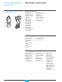
Discovering Masterpact’s
accessories
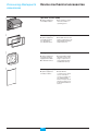
Device mechanical accessories
Operation counter (CDM)
b optional equipment,
one CDM per device.
b the operation counter
sums the number of
operating cycles.
9
E60499A
0039
Escutcheon (CDP)
E60497A
b optional equipment,
one CDP per device
v for fixed device
v for drawout device.
Transparent cover (CCP)
b optional equipment,
one CCP per device
equipped with a CDP
b for drawout devices.
E60498A
b the CDP increases the
degree of protection to IP
40 and IK 07 (fixed and
drawout devices).
b mounted with a CDP,
the CCP increases the
degree of protection to
IP 54 and IK 10 (fixed
and drawout devices).
Blanking plate (OP)
b optional equipment,
one OP per device.
36
b used with the
escutcheon, this option
closes off the door
cut-out of a cubicle not
yet equipped with a
device. It may be used
with the escutcheon for
both fixed and drawout
devices.
Masterpact NT06-16 IEC
Schneider Electric
E60347A
Device mechanical accessories
Transparent cover for pushbutton locking using a padlock,
lead seal or screws
E60346A
b optional equipment,
one locking cover per
device.
b the transparent cover
blocks access (together
or separately) to the
pushbuttons used to
open and close the
device
b locking requires a
padlock, a lead seal or
two screws.
Device locking in the OFF position using a padlock
E60348A
b optional equipment,
one locking system per
device.
b the unit inhibits local or
remote closing of the
device
b up to three padlocks
may be used for locking.
Device OFF position locking kit for keylocks
b optional equipment:
one locking kit (without
keylock) per device
v for Profalux keylo
v for Ronis keylock
v for Kirk keylocks
v for Castell keyloc.
b optional equipment,
one locking system per
device.
E51286A
Ronis
Keylocks required for the device OFF position locking kit
b one or two keylocks
per locking kit
v Ronis:
1 keylock
v Profalux:
1 keylock.
E51287A
Profalux
b the kit inhibits local or
remote closing of the
device.
37
Masterpact NT06-16 IEC
Schneider Electric
Chassis accessories
Top shutter closed
Safety shutters
Bottom shutter closed
E60031A
E60030A
Discovering Masterpact’s
accessories
If specified when ordering the chassis, this
locking function may be adapted to operate
in all positions ("connected", "test" and
"disconnected"), instead of in
"disconnected" position alone.
E51273A
E51286A
Ronis
E51274A
E51287A
Profalux
b optional equipment
b (set of shutters for top
and bottom) drawout,
front/rear connection:
v 3 poles
v 4 poles.
b mounted on the
chassis, the safety
shutters automatically
block access to the
disconnecting contact
cluster when the device
is in the "disconnected"
or "test" positions.
b IP 20 for chassis
connections
b IP 40 for the
disconnecting contact
cluster.
Circuit breaker locking in "disconnected" position
b optional equipment,
one locking system per
device
b keylocks not included:
v for Profalux keylocks
v for Ronis keylocks
v for Castell keylocks
v for Kirk keylocks.
b mounted on the
chassis and accessible
with the door closed, this
system locks the circuit
breaker in "disconnected"
position using one or two
keylocks.
Keylocks required with the "disconnected" position locking
system
b one or two keylocks
per locking system
v Ronis:
1 keylock
1 keylock + one identical
keyloc
2 different key locks
v Profalux:
1 keyl
1 keylock + one identical
keylock
2 different key locks.
38
Masterpact NT06-16 IEC
Schneider Electric
E60011A
Chassis accessories
Door interlock
b optional equipment,
one door interlock per
chassis.
O
OFF
push
b this device inhibits
opening of the cubicle
door when the circuit
breaker is in "connected"
or "test" position.
b it may be mounted on
the left or right-hand side
of the chassis.
b this device prevents
insertion of the racking
handle when the cubicle
door is open.
b it is mounted on the
right-hand side of the
chassis.
E51498A
O OFF
Racking interlock
E59190A
b optional equipment,
one racking interlock per
chassis.
Mismatch protection
E60345A
b optional equipment,
one mismatch protection
device per chassis.
Auxiliary terminal shield (CB)
b optional equipment,
one CB shield per
chassis:
3 poles
4 poles.
E46095A
b mismatch protection
offers twenty different
combinations that the
user may select to
ensure that only a
compatible circuit
breaker is mounted on a
given chassis.
b the shield prevents
access to the terminal
block of the electrical
auxiliaries.
"Connected", "disconnected" and "test" position carriage
switches (CE, CD, CT)
b optional equipment,
one to six carriage
switches
b standard configuration,
0 to 3 CE, 0 to 2 CD,
0 to 1 CT.
v standard
v low level.
39
b the carriage switches
indicate the three
positions:
CE: connected position
CD: disconnected
position (when the
minimum isolation
distance between the
main contacts and the
auxiliary contacts is
reached)
CT: test position.
Masterpact NT06-16 IEC
b changeover contact
b breaking capacity at
cos ϕ = 0.3 (AC12 /
DC12 as per 947-5-1)
v standard, minimum
current 10 mA / 24 V
V AC 240
8 A (rms)
380
8 A (rms)
480
8 A (rms)
690
6 A (rms)
V DC 24/48
2.5 A
125
0.8 A
250
0.3 A
v low level, minimum
current 1 mA / 4 V
V AC 24/48
5 A (rms)
240
5 A (rms)
380
5 A (rms)
V DC 24/48
2.5 A
125
0.8 A
250
0.3 A
Schneider Electric
Inspecting and testing
before use
Initial tests
Procedure
These operations must be carried out in
particular before using a Masterpact device
for the first time.
A general check of the circuit breaker takes only a few minutes and avoids any risk
of mistakes due to errors or negligence.
A general check must be carried out:
b prior to initial use
b following an extended period during which the circuit breaker is not used.
A check must be carried out with the entire switchboard de-energised.
In switchboards with compartments, only those compartments that may be
accessed by the operators must be de-energised.
Electrical tests
Insulation and dielectric-withstand tests must be carried out immediately after
delivery of the switchboard. These tests are precisely defined by international
standards and must be directed and carried out by a qualified expert.
Prior to running the tests, it is absolutely necessary to:
b disconnect all the electrical auxiliaries of the circuit breaker (MCH, MX, XF, MN,
Res electrical remote reset)
b remove the long-time rating plug on the 7.0 A, 5.0 P, 6.0 P, 7.0 P, 5.0 H, 6.0 H,
7.0 H control units. Removal of the rating plug disconnects the voltage
measurement input.
Switchboard inspection
Check that the circuit breakers are installed in a clean environment, free of any
installation scrap or items (tools, electrical wires, broken parts or shreds, metal
objects, etc.).
Conformity with the installation diagram
Check that the devices conform with the installation diagram:
b breaking capacities indicated on the rating plates
b identification of the control unit (type, rating)
b presence of any optional functions (remote ON/OFF with motor mechanism,
auxiliaries, measurement and indication modules, etc.)
b protection settings (long time, short time, instantaneous, earth fault)
b identification of the protected circuit marked on the front of each circuit breaker.
Condition of connections and auxiliaries
Check device mounting in the switchboard and the tightness of power connections.
Check that all auxiliaries and accessories are correctly installed:
b electrical auxiliaries
b terminal blocks
b connections of auxiliary circuits.
Operation
Check the mechanical operation of the circuit breakers:
b opening of contacts
b closing of contacts.
Check on the control unit
Check the control unit of each circuit breaker using the respective user manuals.
40
Masterpact NT06-16 IEC
Schneider Electric
What to do when the circuit
breaker trips
Note the fault
Faults are signalled locally and remotely by the indicators and auxiliary contacts
installed on circuit breakers (depending on each configuration). See page 12 in this
manual and the user manual of the control unit for information on the fault
indications available with your circuit breaker.
Identify the cause of tripping
A circuit must never be reclosed (locally or remotely) before the cause of the fault
has been identified and cleared.
A fault may have a number of causes:
b depending on the type of control unit, fault diagnostics are available. See the
user manual for the control unit.
b depending on the type of fault and the criticality of the loads, a number of
precautionary measures must be taken, in particular the insulation and dielectric
tests on a part of or the entire installation. These checks and test must be directed
and carried out by qualified personnel.
Inspect the circuit breaker following a short-circuit
b check the arc chutes (see page 43)
b check the contacts (see page 43)
b check the tightness of connections (see the device installation manual)
b check the disconnecting-contact clusters (see page 43).
Reset the circuit breaker
The circuit breaker can be reset locally or remotely. See page 12 in this manual for
information on how the circuit breaker can be reset.
41
Masterpact NT06-16 IEC
Schneider Electric
Maintaining Masterpact
performance
Recommended maintenance
program
Recommended program for devices used
under normal operating conditions:
Ambient temperature: -5 °C / +70 °C
Normal atmosphere
Periodic inspections required
Interval
Operation
b open and close the device
locally and remotely,
successively using the various
auxiliaries
b test the operating sequences
b test the control unit using
the mini test kit
every two years or
b check the arc chutes
when the control-unit b check the main contacts
maintenance indicator b check the tightness
reaches 100
of connections
each year
Procedure
v see pages 10 and 11
v see pages 10 and 11
v see the user manual of
the control unit
v see page 43
v see page 43
v see the device
installation manual
Parts requiring replacement, depending on the number of
operating cycles
The following parts must be replaced periodically to lengthen the service life of the
device (maximum number of operating cycles).
Part
Intervening entity
b user
b inspection: user
b replacement:
Schneider After Sales Support
MCH gear motor
b user
mechanical interlocks b user
connecting-rod
b Schneider After Sales
springs
Support
MX/MN/XF
b user
arc chutes
main contacts
Description or
procedure
v see page 43
v see page 43
v see page 9
v see pages 10 and 11
Part replacement must be programmed on the basis of the data below, listing the
service life of the various parts in numbers of O/C cycles at the rated current.
Number of O/C cycles at the rated current
Type of
circuit
breaker
NT08 to 16
type H1/H2
NT08 to 10
type L1
42
Maximum
Maximum service life in
service life
electrical durability
in mechanical
durability
12500
12500
Masterpact NT06-16 IEC
440 V: 6000
690 V: 3000
440 V: 3000
690 V: 2000
MX / XF / MN
releases
12500
12500
Schneider Electric
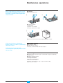
Maintenance operations
Arc chutes
1
E60000A
b remove the fixing screws
E60045A
Before undertaking any maintenance work,
de-energise the installation and fit locks or
warnings in compliance with all applicable
safety standards.
22
b check the arc chutes:
v chamber intact
v separators not corroded.
33
E60002A
E60001A
If necessary, replace the arc chutes.
b refit the arc chutes and secure with a tightening torque of 1.5 Nm.
If the control unit has a maintenance
indicator, there is no need to systematically
check the contacts.
Wear of main contacts
b remove the arc chutes
b visually check the contacts.
If necessary, contact Schneider After-sales support.
If the contacts are worn, have the
concerned poles replaced by the Schneider
service centre.
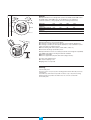
Disconnecting-contact clusters
b grease the contacts using the grease recommended on page 44, supplied by
Schneider Electric
b check the contacts as follows:
v open the circuit breaker
v de-energise the busbars
v disconnect the circuit breaker
v remove the circuit breaker
v check the contact fingers (no sign of copper should be visible).
Replace any worn clusters.
43
Masterpact NT06-16 IEC
Schneider Electric
Maintaining Masterpact
performance
Ordering replacement parts
Electrical accessories
The electrical accessories that may require replacement are the following:
b MCH gear motor
b MX opening release(s)
b XF closing release
b MN undervoltage release.
E60002A
See pages 33 and 34 in the "Auxiliaries for remote operation" section for their
characteristics.
Arc chutes
E60349A
b 1 arc chute:
v type H1
v type L1.
b one chute per pole.
Front
E60496A
b 1 per 3- or 4-pole
device.
Charging handle
E51336A
b 1 per device.
Crank
b 1 per device.
Support for MX / XF / MN releases
E46237A
b 1 per device.
Disconnecting-contact clusters
b 1 cluster.
Grease for disconnecting-contact clusters
b 1 can.
44
Masterpact NT06-16 IEC
Schneider Electric
45
Masterpact NT06-16 IEC
Schneider Electric
Maintaining Masterpact
performance
Troubleshooting and
solutions
Problem
Probable causes
Solutions
b circuit breaker padlocked or
keylocked in the "open" position
v disable the locking fonction
circuit breaker cannot be closed locally or remotely
b circuit breaker interlocked
mechanically in a source changeover
system
v check the position of the other
circuit breaker in the changeover
system
v modify the situation to release the
interlock
b circuit breaker not completely connected v terminate racking in (connection)
of the circuit breaker
b the reset button signalling a fault trip
has not been reset
circuit breaker cannot be closed remotely but can be
opened locally using the closing pushbutton
unexpected tripping without activation of the reset
button signalling a fault trip
unexpected tripping with activation of the reset button
signalling a fault trip
instantaneous opening after each attempt to close the
circuit breaker with activation of the reset button
signalling a fault trip
v clear the fault
v push the reset button on the front
of the circuit breaker
b stored energy mechanism not charged
v charge the mechanism manually
v if it is equipped with a an MCH gear
motor, check the supply of power to
the motor. If the problem persists,
replace the gear motor (MCH)
b MX opening shunt release
v there is an opening order.
permanently supplied with power
Determine the origin of the order. The
order must be cancelled before the
circuit breaker can be closed
b MN undervoltage release not supplied
v there is an opening order.
with power
Determine the origin of the order.
v check the voltage and the supply
circuit (U > 0.85 Un). If the problem
persists, replace the release
b XF closing release continuously
v cut the supply of power to the XF
supplied with power, but circuit breaker not closing release, then send the closing
"ready to close" (XF not wired in series
order again via the XF, but only if the
with PF contact)
circuit breaker is "ready to close"
b permanent trip order in the presence of
v Disable these protection functions
a Micrologic P or H control unit with
on the Micrologic P or H control unit
minimum voltage and minimum frequency
protection in Trip mode and the control
unit powered
b closing order not executed by the XF
v check the voltage and the supply
closing release
circuit (0.85 - 1.1 Un). If the problem
persists, replace the XF release
b MN undervoltage release supply
v check the voltage and the supply
voltage too low
circuit (U > 0.85 Un)
b load-shedding order sent to the MX
v check the overall load on the
opening release by another device
distribution system
v if necessary, modify the settings of
devices in the installation
b unnecessary opening order from the
v determine the origin of the order
MX opening release
a fault is present :
b overload
v determine and clear the causes of
b earth fault
the fault
b short-circuit detected by the control
v check the condition of the circuit
unit
breaker before putting it back into
service
b thermal memory
v see the user manual of the control
unit
v press the reset button
b transient overcurrent when closing
v modify the distribution system or the
control-unit settings
v check the condition of the circuit
breaker before putting it back into
service
v press the reset button
b closing on a short-circuit
v clear the fault
v check the condition of the circuit
breaker before putting it back into
service
v press the reset button
46
Masterpact NT06-16 IEC
Schneider Electric
Problem
circuit breaker cannot be opened remotely, but can be
opened locally
Probable causes
Solutions
b opening order not executed by the MX
opening release
v check the voltage and the supply
circuit (0.7 - 1.1 Un).
If the problem persists, replace the
MX release
v drop in voltage insufficient or
residual voltage (> 0.35 Un) across
the terminals of the undervoltage
release. If the problem persists,
replace the MN release
v contact a Schneider service centre
b opening order not executed by the MN
undervoltage release
circuit breaker cannot be opened locally
circuit breaker cannot be reset locally but not remotely
nuisance tripping of the circuit breaker with activation
of the reset button signalling a fault trip
impossible to insert the crank in connected, test or
disconnected position
impossible to turn the crank
circuit breaker cannot be removed from chassis
circuit breaker cannot be connected (racked in)
circuit breaker cannot be locked in disconnected
position
circuit breaker cannot be locked in connected, test or
disconnected position
b operating mechanism malfunction or
welded contacts
b insufficient supply voltage for the
MCH gear motor
b reset button not pushed-in completely
b a padlock or keylock is present on the
chassis or a door interlock is present
b the reset button has not been pressed
b circuit breaker not in disconnected
position
b the rails are not completely out
b chassis/circuit breaker mismatch
protection
b the safety shutters are locked
b the disconnecting-contact clusters are
incorrectly positioned
b chassis locked in disconnected
position
b the reset button has not been pressed,
preventing rotation of the crank
b the circuit breaker has not been
sufficiently inserted in the chassis
b the circuit breaker is not in the right
position
b the cranck is still in the chassis
b check that locking in any position is
enabled
b the circuit breaker is not in the right
position
b the cranck is still in the chassis
47
Masterpact NT06-16 IEC
v check the voltage and the supply
circuit (0.7 - 1.1 Un).
If the problem persists, replace the
MCH release
v push the reset button in completely
v disable the locking function
v press the reset button
v turn the crank until the circuit
breaker is in disconnected position
and the reset button out
v pull the rails all the way out
v check that the chassis corresponds
with the circuit breaker
v remove the lock(s)
v reposition the clusters
v disable the chassis locking function
v press the reset button
v insert the circuit breaker completely
so that it is engaged in the racking
mechanism
v check the circuit breaker position by
making sure the resett button is out
v remove the crank and store it
v contact a Schneider service centre
v check the circuit breaker position by
making sure the rese button is out
v remove the crank and store it
Schneider Electric
E60004A
E60003A
Checking Masterpact
operating conditions
Ambient temperature
Masterpact NT devices can operate under the following temperature conditions:
b the electrical and mechanical characteristics are stipulated for an ambient
temperature of -5 °C to +70 °C
b circuit-breaker closing is guaranteed down to -35 °C
b Masterpact NW (without the control unit) can be stored in an ambient
temperature of -40 °C to +85 °C
b the control unit can be stored in an ambient temperature of -25 °C to +85 °C.
Extreme atmospheric conditions
Masterpact NT devices have successfully passed the tests defined by the following
standards for extreme atmospheric conditions:
b IEC 68-2-1: dry cold at -55 °C
b IEC 68-2-2: dry heat at +85 °C
b IEC 68-2-30: damp heat (temperature +55 °C, relative humidity 95%)
b IEC 68-2-52 level 2: salt mist.
Masterpact NT devices can operate in the industrial environments defined by
standard IEC 947 (pollution degree up to 4).
E60005A
It is nonetheless advised to check that the devices are installed in suitably cooled
switchboards without excessive dust.
Vibrations
Masterpact NT devices resist electromagnetic or mechanical vibrations.
Tests are carried out in compliance with standard IEC 68-2-6 for the levels required
by merchant-marine inspection organisations (Veritas, Lloyd’s, etc.):
b 2 to 13.2 Hz: amplitude ±1 mm
b 13.2 to 100 Hz: constant acceleration 0.7 g.
Excessive vibration may cause tripping, breaks in connections or damage to
mechanical parts.
48
Masterpact NT06-16 IEC
Schneider Electric
E60006A
Altitude
E60007A
2000 m
Masterpact NT devices are designed for operation at altitudes under 2000 metres.
At altitudes higher than 2000 metres, the modifications in the ambient air
(electrical resistance, cooling capacity) lower the following characteristics.
altitude (m)
dielectric withstand
voltage (V)
rated insulation level (V)
rated operational
voltage (V)
rated current (A) at 40 °C
2000
3500
3000
3150
4000
2500
5000
2100
1000
690
900
590
700
520
600
460
1 x In
0.99 x In
0.96 x In
0.94 x In
Electromagnetic disturbances
Masterpact NT devices are protected against:
b overvoltages caused by devices that generate electromagnetic disturbances
b overvoltages caused by an atmospheric disturbance or by a distribution-system
outage (e.g. failure of a lighting system)
b devices emitting radio waves (radios, walkie-talkies, radar, etc.)
b electrostatic discharges produced by users.
Masterpact NT devices have successfully passed the electromagnetic-compatibility
tests (EMC) defined by the following international standards:
b IEC 947-2, appendix F
b IEC 947-2, appendix B (trip units with earth-leakage function).
The above tests guarantee that:
b no nuisance tripping occurs
b tripping times are respected.
Cleaning
v non-metallic parts:
never use solvent, soap or any other cleaning product. Clean with a dry cloth only
v metal parts:
clean with a dry cloth whenever possible. If solvent, soap or any other cleaning
product must be used, make sure that it does not come into contact with
non-metallic parts.
49
Masterpact NT06-16 IEC
Schneider Electric
Schneider Electric Industries SAS
5, rue Nadar
92506 Rueil-Malmaison Cedex
France
Tel: +33 (0)1 41 29 82 00
Fax: +33 (0)1 47 51 80 20
http://www.schneider-electric.com
http://www.merlin-gerin.com
51201116AA-E1
As standards, specifications and designs develop from time, always ask for confirmation of the
information given in this publication.
Printed on recycled paper
Designed by: SEDOC
Photos: Schneider
Printed by:
11-2006