1
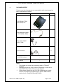
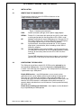
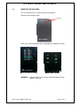
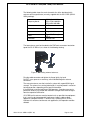
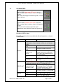
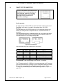
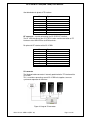
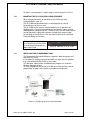
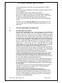
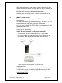
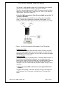
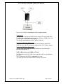
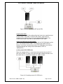
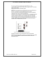
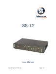
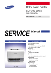
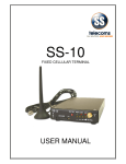
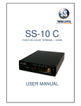
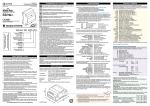
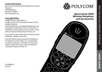
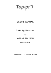
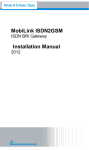
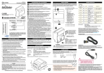
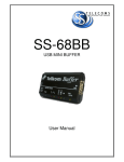
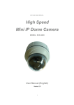
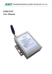
SS-15 BRI
MULTI SIM (ISDN 2 GSM)
USER MANUAL
SS-15 BRI MULTI SIM (ISDN 2 GSM) USER MANUAL
Revision History:
Revision 01
Revision 02
Revision 03
New document
LED`s status update
Added Multi Sim Content
14 September 2009
02 December 2009
10 March 2010
CONTENTS
1.
INTRODUCTION
3
2.
WHAT IS SS-15 BRI MULTI SIM (ISDN 2 GSM)?
3
3.
PACKAGE CONTENT
4
4.
4.1
4.2
4.3
4.4
4.5
4.6
4.7
4.8
4.9
4.10
4.11
INSTALLATION
IDENTIFYING THE CONNECTORS
CONFIGURING THE SIM CARDS
INSERTING THE SIM CARDS
CONNECTING THE CABLES
INSTALLING THE EXTERNAL ANTENNAS
JUMPER SETTINGS
POWER UP SS-15 BRI (ISDN 2 GSM)
LED INDICATORS
PINOUT FOR THE CONNECTORS
MOUNTING THE SS-15 BRI (ISDN 2 GSM) EQUIPMENT
INSTALLING THE PROGRAMMING TOOL
5
5
5
6
7
7
9
10
11
12
14
14
5.
5.1
5.2
OPERATION AND MODES OF CONNECTION
ROUTING FOR LEAST COSTS
MODES OF CONNECTION
15
15
16
6.
OPERATING ENVIRONMENT
22
7.
BENEFITS
23
6.
CONTACT DETAILS
24
DOC. NO: SS-15BRI-14 (REV. 01)
Page 2 of 24
SS-15 BRI MULTI SIM (ISDN 2 GSM) USER MANUAL
1.
INTRODUCTION
By purchasing an SS-15 BRI Multi SIM you have opted for:
cutting down the costs of your cellular calls;
ISDN to GSM interface with LCR capabilities;
excellent audio quality;
availability of SMS functions;
perfect compatibility to ISDN private branch exchanges (PBX);
routing functions assured even when used as standalone unit;
full compatibility with GSM 900/1800 or 850/1900 networks;
Load balancing between 4 sims per module.
saving of ports in your PBX exchange and
2.
Easy and quick installation and usage.
WHAT IS SS-15 BRI Multi SIM (ISDN 2 GSM)?
By interfacing between an ISDN phone exchange and the mobile telephony
network (GSM 900/1800 or 850/1900) cuts down the costs of fixed-to-GSM and
GSM–to-fixed calls.
The SS-15 BRI was designed to be connected to any ISDN phone exchange
so it meets standard ISDN PBX requirements.
It may be used as GSM interface for an ISDN a phone exchange. Even when
used as standalone unit with an ISDN phone set it can still perform routing of
the calls for minimum costs. Also, by means of a terminal adapter it can be
used with analogue (standard) telephones or with a payphone.
The unit works primarily in voice mode by re-routing incoming or outgoing
calls through the corresponding wireless network. This way there is only cost
of a mobile-to-mobile call inside the same carrier network, instead of the cost
of a fixed-to-mobile call.
The interface enables several types of ISDN connections and may be used for
services such as call forwarding (conditioned or unconditioned), DISA and
voice messages.
When connected to a computer, the SS-15 BRI may be used to receive and
send out SMS’s.
By connecting SS-15 BRI to an ISDN phone exchange, all local extensions
can make calls to GSM networks while keeping down the costs. Also, when
making a call the subscriber is no longer subjected to RF radiations from the
cell-phone. The external antennas can then also be placed for optimal
reception (higher intensity of the radio signal).
Since SS-15 BRI can send billing pulses, a public telephone (payphone) can
also be used by means of terminal adapter.
Its installation is simple; just insert the SIM cards and plug in the cables (serial
configuration, ISDN lines, external antennas, power adapter). This comes
very useful for the SOHO (small office/ home office) market.
DOC. NO: SS-15BRI-14 (REV. 01)
Page 3 of 24
SS-15 BRI MULTI SIM (ISDN 2 GSM) USER MANUAL
3.
PACKAGE CONTENT
Please ensure that all components are accounted for and that no damage has
been sustained during transport.
Item
Image
Pcs/ Note
SS-15 BRI MULTI SIM
(ISDN 2 GSM) Unit.
1
Serial programming cable
for SS-15 (ISDN 2 GSM)
1*
Power supply adapter
12VDC / 2,08A
1
External antennas
1-2 **
CD with OAM software
-
User’s manual
-
1 ***
Notes:
*
**
***
The package also contains two connecting cable for TE and NT
interfaces
Depending on what SS-15 BRI (ISDN 2 GSM) model it is (with one or
two GSM modules) there will be one or two antennas.
OAM software supplied with the SS-15 BRI (ISDNoam.exe) includes
functions for configuring (programming) the ISDN to GSM interface,
routing of calls, sending and receiving of SMS’s.
DOC. NO: SS-15BRI-14 (REV. 01)
Page 4 of 24
SS-15 BRI MULTI SIM (ISDN 2 GSM) USER MANUAL
4.
INSTALLATION
4.1
IDENTIFYING THE CONNECTORS
The back of the enclosure of the SS-15 BRI unit features all the
supply/voice/data connectors:
Figure 1. Identifying the connectors
PWR:
Female connector, jack type, for the power supply adapter
SERIAL:
Female RJ-11 connector with special pin-out, for the serial cable
used for configuration (for the connection to PC a DB9 is used)
Network Termination for 4-wire ISDN phone line. Connects SS-15
BRI (ISDN 2 GSM) to the TE of the ISDN PBX or the ISDN phone
set (analogue phone may be used via terminal adapter)
Synchronization, connections paralleled with TE slot. Used for
clock signal synchronization, when cascading several ISDN 2
GSM units together.
Terminal Equipment connector for ISDN is used for connecting to
an ISDN phone exchange or to the ISDN public telephony network
and also, for connecting more than one SS-15 BRI unit to the
same PBX.
NT:
SY:
TE:
The two FME connectors for the external antennas are located on
top of the SS-15 BRI while the slots for the SIM cards are inside.
4.2
CONFIGURING THE SIM CARDS
The SIM cards that will be used with SS-15 BRI must be activated by the
corresponding GSM operator. It must also be properly configured before
insertion in the GSM slot of the equipment. The configuration of the SIM cards
is performed using a GSM phone.
Disable GSM services – most GSM operators assure several services
(redirection of calls, vocal mailbox) concerning the handling of incoming calls.
These are very useful when the cell-phone is busy or disconnected; it is an
advantage to use the call forwarding features provided by the GSM carrier. But
when the SS-15 BRI interface is used together with a phone exchange it is
generally better to disable those services because it can be performed locally
with fewer costs.
Disable Auto-re-dialling and Auto-answer – these options must be disabled if
they are provided by the GSM operator.
DOC. NO: SS-15BRI-14 (REV. 01)
Page 5 of 24
SS-15 BRI MULTI SIM (ISDN 2 GSM) USER MANUAL
4.3
INSERTING THE SIM CARDS
The SS-15 Multi Sim has a metal cover on the front panel.
Remove screw and open cover.
Screw
Insert Sims into corresponding slots as indicated on the back of the cover.
WARNING:
Unplug the SS-15 unit from the main outlet before insert or
replace a SIM card.
DOC. NO: SS-15BRI-14 (REV. 01)
Page 6 of 24
SS-15 BRI MULTI SIM (ISDN 2 GSM) USER MANUAL
1.4
CONNECTING THE CABLES
Connect the data, phone and power cables as shown in the drawing below:
Other ISDN interfaces
Figure 3. Connecting the cables
Use ISDN cables to connect the unit to the ISDN PBX (or other ISDN
terminals). Connect the cables from the corresponding ISDN device to the
SS-15 BRI unit. For more detailed information on correct connections refer to
par. 5.2. “Modes of connection”.
1. For each SS-15 BRI ISDN interface, insert one end of the 4-wire ISDN
phone cable in the TE or NT connector of the SS-15 BRI . The opposite other
end of the cable must be connected to the corresponding local or junction
interface of the ISDN PBX or to the ISDN phone. The pinout ofRJ-45
connectors for TE and NT interfaces is shown in tables in par.4.9 “Pinout for
connectors” .Select the individual NT, TE or SY connections in accordance
with par. 5.2. „Modes of connection”. In order to achieve a good operation,
the pattern of connections required for the application needs to be known
(links required by the ISDN phone exchange or telephone terminals).
2. Serial programming connection – To be able to adjust configuration of the
ISDN 2 GSM interface using the Programming Tool, the equipment must be
connected to a PC. The connection is performed by means of a special cable
that connects to the „SERIAL” slot of the SS-15 device. The serial connection
is also necessary for sending and receiving SMS messages from the PC.
3. Insert the jack of the power supply adapter (shipped in the SS-15 BRI
package) into the PWR connector. Do not plug the adapter into the
receptacle of the 230V ac mains outlet yet.
If starting up the SS-15 BRI and the antennas are not connected, the
transmitter of the GSM module could be damaged.
1.5
INSTALLING THE EXTERNAL ANTENNAS
SS-15 BRI features two RF connectors on top for connecting the antennas for
the wireless network. The following may be used:
the wideband antenna supplied with the package, with cable and magnetic
base (see below characteristics) or
other kinds of external antennas with higher gain or directivity (Yagi), if the
need arises.
DOC. NO: SS-15BRI-14 (REV. 01)
Page 7 of 24
SS-15 BRI MULTI SIM (ISDN 2 GSM) USER MANUAL
The following table shows the main characteristics of the dual-band stick
antennas with magnetic base (currently supplied with the SS-15 BRI (ISDN 2
GSM) package).
Frequency bands
GSM 890-960 MHz
PCN 1710-1880 MHz
PCS1850-1990 MHz
Gain
2 dBi
Polarization
Vertical
Base
Magnetic, 2,8cm
Cable
Connector
Type RG174, length
2,5 m
Female FME
The two antennas must be threaded to the FME male connectors located on
top of the SS-15 BRI unit, as shown in the following drawing.
Figure 4. Connecting external antennas.
Plug the cable connector and tighten the flange lightly, by hand.
Do NOT use a spanner or screw key, which could damage the antenna
connectors.
The external antennas must be installed in a place with a good GSM signal
strength. The antenna has vertical polarization; it must be placed in vertical or
horizontal position, depending of the local field condition.
If the SIM cards used are for different GSM operators, it may be necessary to
place each antenna in a location with maximum strength of the received signal
from the respective GSM carrier.
SS-15 BRI and its antennas must be located as far as possible from equipment
that is sensitive to electromagnetic interferences (radios, audio or video
appliances, computer monitor, TV receivers etc). If placing the SS-15 BRI
interface or its antennas too close to such appliances, their operation could be
affected.
DOC. NO: SS-15BRI-14 (REV. 01)
Page 8 of 24
SS-15 BRI MULTI SIM (ISDN 2 GSM) USER MANUAL
Note1: The antennas of the SS-15 BRI interface send out RF energy so they
should NOT be placed very close to people. Since the GSM interface transmits
for longer periods of time, being used by several people (most of the calls of
local subscribers are routed through it) the radiation will accordingly be higher
than for a cell-phone used only infrequently, by a single person.
Note2: Remember to connect the antennas before powering up the SS-15 BRI,
to avoid damage to the transmitters of the GSM modules.
1.6
JUMPER SETTINGS
The SS-15 BRI features several jumpers located on the printed circuit board,
inside the enclosure. These jumpers control functions seldom needed, therefore,
under normal operation these settings do not need to be changed.
4.6.1.
Bootloader enable
Use
If an abnormal interruption occurred in the loading of an image file, use the JP5
jumper.
To fix this problem, set the jumper on the JP5 pins to force the bootloader to
start. In order to load a new image file please refer to the isdncfg OAM manual.
Remember to take the jumper off pins JP5 before resuming normal operation
of the ISDN 2 GSM equipment.
Location
Figure 6. JP5 jumper location
Jumper JP5 is located near the top left corner of the printed circuit board of the
SS-15 BRI. Immediately to the right of JP5 the connector for the external
antenna can be seen. JP5 is alone (no other jumpers close to it) and it is in a
vertical position.
4.6.2.
Terminal resistors
Use
These pairs of jumpers (JAN1 and JAN2 for the NT interface, JAT1 and JAT2 for
the TE interface) configure the impedance matching (termination) resistors for
the respective interfaces.
By default, these jumpers are ON so the terminal resistors are connected. The
jumpers should be taken OFF if terminal resistors are not required.
When several ISDN devices are connected to an ISDN line, the line must end
with impedance matching resistors, also called terminal resistors. This is
required, for instance, when cascading several SS-15 interfaces and using
synchronization.
DOC. NO: SS-15BRI-14 (REV. 01)
Page 9 of 24
SS-15 BRI MULTI SIM (ISDN 2 GSM) USER MANUAL
One solution for termination is to use a terminal block with matching resistors
inside. But if the last device is an SS-15 BRI, the termination resistors that are
included with the equipment can be used. Remember, out of several SS-15 BRI
units cascaded on the ISDN line, only the last unit must have the termination
resistors enabled.
Location
Figure 7. Location of JAT1, JAT2, JAN1 and JAN2 jumpers
The pairs of jumpers (JAN1 and JAN2 for the NT interface, JAT1 and JAT2 for
the TE interface) are located towards the right edge of the SS-15 BRI printed
circuit board, at middle-bottom. Each pair of jumpers is near a black rectangle
(ISDN transformers). JAN1 and JAN2 are the first pair; below them is the
second pair, JAT1 and JAT2 respectively. The jumpers are in horizontal
positions.
1.7
POWER UP SS-15 BRI
Insert the jack of the power supply adapter into the PWR connector.
Plug the adapter into the receptacle of the 230V AC mains outlet. The SS-15
BRI will start working immediately. The green LED indicator (PWR) should be
lighting up.
Warning: To avoid accidents or damage to the equipment, follow the installation
steps described earlier. The supply plug of the adapter must be the last
connection made. Do NOT connect the cables for serial configuration, phone or
PBX while the SS-15 BRI unit is powered. Also, don’t take out the antennas
while the SS-15 is in operation.
DOC. NO: SS-15BRI-14 (REV. 01)
Page 10 of 24
SS-15 BRI MULTI SIM (ISDN 2 GSM) USER MANUAL
1.8
LED INDICATORS
The SS-15 BRI (Single colour LED version) has six
LED’s as optical status indicators, shown in the figure to
the right.
Each status LED displays one colour only and is in either
an on or off state.
The SS-15 BRI (Dual-colour LED version) has three
LED’s as optical status indicators, shown in the figure to
the right.
The first two are Dual-colour (red and/or green –
depending on status) while the Power led is green only.
Functions of LED`s status
Each LED may light continuously or blink with different frequencies, as shown in
the table below:
LED
GSM 0 & 1
ISDN TE & NT
POWER
DOC. NO: SS-15BRI-14 (REV. 01)
STATUS
SIGNIFICANCE
The Dual-colour LED version LED shows the status of
GSM modules. Green indicates GSM 0 and red indicates
GSM 1.
Blinking fast,
The GSM module is initializing
5 Hz
Blinking,
Wrong PIN number (PIN error)
1 Hz
GSM module is searching for the
Blinking slow,
network (antenna not installed, or
0.5 Hz
SS-15 not in the coverage area of
the GSM network )
GSM module has registered to the
Off
network and is in standby
On,
GSM module is busy (in a call or just
Continuously
allocated)
Information about synchronization of ISDN interfaces. On
the Dual-colour LED version, the green indicates the NT
interface and red refers to the TE interface of SS-15.
Interface not synchronized.
Blinking 0.25 sec
For example if the NT LED blinks
then one sec off
0.25 sec then one sec off, the NT
interface is not synchronized.
Off
The ISDN interface is synchronized.
Lights continuously
green
The supply voltage is present
Off
There is no-supply voltage
Page 11 of 24
SS-15 BRI MULTI SIM (ISDN 2 GSM) USER MANUAL
1.9
PINOUT FOR THE CONNECTORS
The SS-15 BRI features four data connectors
at the bottom of its case. All connectors are
of the same type, female RJ-45, but they
have different functions. Please read the
paragraph carefully and perform the
connections accordingly.
Serial connector
For programming the SS-15 BRI the special connection cable must be used.
The special serial cable is included in the package of the SS-15 BRI
equipment.
The end towards the SS-15 BRI features an RJ11 connector while the end
towards the COM port of the computer features a standard female DB-9
connector.
In the drawing below the pin numbering can be seen (from left to right) of the
RJ11 female connector of the SS-15 BRI and the corresponding male RJ11
male connector on the serial programming cable.
Figure 8.Serial connector
See table below for pinout of cable and its connectors.
RJ11
Symbol
DB-9
1
2
3
4
5
6
DSR
RxD
GND
TxD
DTR
CTS
6
3
5
2
4
8
Signal
Data Set Ready, input
Receive Data, input
Signal Ground
Transmit Data, output
Data Terminal Ready, input
Clear To Send, input
TE connector – used for connecting the SS-15 BRI TE interface.
The TE interface of the SS-15 BRI unit is used for connection to NT interfaces
of the ISDN private branch exchange or of the ISDN public telephony network.
TE interfaces are provided with embedded termination resistors. These
resistors may be enabled by means of corresponding jumpers, the pair JAT1
and JAT2.
DOC. NO: SS-15BRI-14 (REV. 01)
Page 12 of 24
SS-15 BRI MULTI SIM (ISDN 2 GSM) USER MANUAL
See table below for pinout of TE interface.
Pin
1
2
3
4
5
6
7
8
Signal
Not connected
Not connected
Tx
Rx
Rx
Tx
Not connected
Not connected
NT connector – used for connecting the SS-15 BRI NT interface.
The NT ISDN interface of the SS-15 BRI is to be used for connection to TE
interfaces of the ISDN PBX or to ISDN terminals.
For pinout of NT interface of the SS-15 BRI:
Pin
1
2
3
4
5
6
7
8
Signal
Not connected
Not connected
Rx
Tx
Tx
Rx
Not connected
Not connected
SY connector
The Synchronization connector is internally paralleled to the TE interface of the
SS-15 BRI.
This is used when connecting several SS-15 BRI units together, to ensure
synchronous operation of all devices.
Figure 9. Usage of SY connector
DOC. NO: SS-15BRI-14 (REV. 01)
Page 13 of 24
SS-15 BRI MULTI SIM (ISDN 2 GSM) USER MANUAL
For details see paragraph 4.2, about modes of connecting the SS-15 unit.
1.10
MOUNTING THE SS-15 BRI (ISDN 2 GSM) EQUIPMENT
When selecting the location for mounting the SS-15 BRI refer to the
recommendations in par. 6.1.
The SS-15 BRI can be placed either in a vertical position on a wall or
horizontally on a desk or in a shelf.
The SS-15 BRI and its antennas must be located as far as possible from
equipment that is sensitive to electromagnetic interferences (radios, audio or
video appliances, computer monitor, TV receivers etc). Also, the GSM antennas
must be mounted in a place with maximum strength of the received signal.
For mounting the SS-15 BRI on a wall, the mounting kit must be used (Metal
Plate) provided by SS Telecoms.
Fix the Metal Plate to the wall.
Then Hang the case of SS-15 BRI
on the two metal Pins and push it
down to get it fixed.
1.11
Figure 10. Mounting SS-15 on a wall
INSTALLING THE PROGRAMMING TOOL
The Programming Tool called ISDNoam is required in order to configure and
control the SS-15 BRI.
It also allows the sending and receiving of SMS messages from the computer
that is connected to the SS-15 BRI via serial cable.
This Operation, Administration, and Maintenance program runs under the
Windows Operating System.
To install the program, connect the SS-15 BRI to the PC that will be used for
programming, by means of the special serial cable for configuration.
Figure 11. Configuring SS-15 via serial connection
DOC. NO: SS-15BRI-14 (REV. 01)
Page 14 of 24
SS-15 BRI MULTI SIM (ISDN 2 GSM) USER MANUAL
Set the communication on the COM serial channel where the SS-15 BRI is
connected.
Insert the CD into the CDROM drive and copy the structure of folders and files
to the hard disk drive.
Run the ISDNoam.exe file from the folder on the hard disk
By means of the graphic interface of the configuration program, begin to
adjust the SS-15 BRI settings (parameters for GSM modules, ISDN TE and
NT interfaces, routing table, CLIP table, name of connection, etc.)
Establish the settings according to the routing functions that the application
requires.
For details, refer to the Operating Manual for the Programming Tool. The
manual includes several examples of configuration of parameters for usual
applications.
2.
OPERATION AND MODES OF CONNECTION
5.1
ROUTING FOR LEAST COSTS
No matter which mode of connection is used, the purpose of the SS-15 BRI is to
achieve Least Cost Routing of calls. The LCR function of the SS-15 BRI
interface ensures that in each case calls (incoming or outgoing) are routed
through the direction with minimum costs. For example, if a local subscriber of
the PBX makes a call, the prefix will be analyzed and the call will be routed
accordingly, either to the public ISDN network or to one of the GSM operators.
This way, instead of paying for a fixed-to-mobile call, there will only be the low
cost of a fixed-to-fixed of mobile-to-mobile call inside the same network. This
holds true also for calls coming in from agents in the field who make calls from
mobile phone - they will pay just for a mobile-to-mobile call, avoiding
interconnection fees. Using the DISA feature, the mobile callers may get the
extension they want, without need for a human operator of the PBX.
Alternatively, the two GSM channels of the SS-15 BRI may feature SIM cards for
the same mobile provider, but with different subscriptions. The Programming
Tool will select the best subscription for any given moment of time (for example,
the operator that provides lower tariff by night or during weekends).
Another instance of getting lower tariff by using the SS-15 BRI is when several
subscribers of the PBX make calls to a certain mobile provider. Since most of
the calls to that provider will be routed through a specific GSM module of the
SS-15 BRI, for that module a SIM with convenient tariff rate (low cost per minute
for a very large number of minutes used) may be used.
In case of connecting several SS-15 BRI units to an ISDN phone exchange, the
possibilities of routing calls for least costs are even better.If all GSM modules in
an SS-15 BRI interface are engaged (busy), the call to a mobile network may
not only be rejected but instead routed through another SS-15 BRI connected to
the same PABX.
The Programming Tool uses CLIP to check the identity of the callers against a
data base. Thus calling can be restricted to certain selected (authorized)
subscribers, avoiding unnecessary costs.
Caller identification may be used for automated routing of calls.
All incoming calls that contain information about the phone number of the
subscriber (ID) will be checked by the Programming Tool against the CLIP
routing list. Depending upon the “Action” that has been set up, the program
will route the call accordingly, to the operator of the PBX, to a certain local
extension or will provide DISA tone.
DOC. NO: SS-15BRI-14 (REV. 01)
Page 15 of 24
SS-15 BRI MULTI SIM (ISDN 2 GSM) USER MANUAL
DISA – direct inward access – allows callers to select the extension they want
without the help from an operator, via DTMF codes. Also, they can dial out of the
exchange.
If the incoming ID is missing, the default routing options apply.
With the “Nr. of Dialled Digits” option the SS-15 BRI makes the call
immediately after receiving the last digit - any digit sent afterwards will be
ignored.
5.2
MODES OF CONNECTION
There are a few options of connecting the SS-15 BRI equipment to an ISDN
phone exchange.
The ISDN 2 GSM interface can be connected either as TE, when it acts as a
terminal equipment, or as NT, when it simulates ISDN network.
It may also be used as a pass-through device that is “transparent” for the
calls. In this case the SS-15 BRI (ISDN 2 GSM) is inserted between the public
ISDN network and the PBX.
These three basic modes of connecting the SS-15 BRI can be combined in
different ways, as shown further.
a) SS-15 BRI connected via NT to a TE junction of the PABX
The NT connector of the SS-15 BRI linked to the TE of the PABX.
The TE of the PABX goes to the public ISDN. The TE interface can be
used to get the clock signal for synchronization, as shown below.
Figure 12. SS-15 BRI connected to TE junction of PBX
Outgoing from PABX
The PBX routes the calls to mobile networks through the SS-15 BRI unit. The
SS-15 BRI may use one or two directions for this (DIR0 for module GSM0,
one mobile network, DIR1 for module GSM1, the other mobile operator)
Incoming GSM to PABX
DOC. NO: SS-15BRI-14 (REV. 01)
Page 16 of 24
SS-15 BRI MULTI SIM (ISDN 2 GSM) USER MANUAL
The decision is taken depending upon the CLIP GSM table or the GSM port
settings if the incoming phone number is not found in the table.
The call is sent only through the SS-15 BRI’s TE interface. In the CLIP-GSM
table, the “ACTION” field value must be set on “NT” and the “Port” field from
“GSM settings” menu will be set on “NT”.
b) The SS-15 BRI connected via TE to NT local of PABX and via NT to TE
junction of the PABX
The NT connector of the SS-15 BRI link to one TE junction of the PABX.
Other TE junction of the PABX goes to the public ISDN network. The TE
connector of the SS-15 BRI unit goes to the NT of a local board of the PABX
Figure 13. SS-15 BRI connected to PBX with both NT and TE interfaces
Outgoing from PABX
The PABX unit verifies the number dialled and routes the call for the public
network through the dedicated interface and the call for the mobile network
through the SS-15 BRI’s NT interface. The SS-15 BRI unit selects one mobile
network operator to send the call.
Incoming to PABX
Calls get into PABX via TE connector. When an incoming GSM call comes in,
if the setting in the GSM window is Operator, the call will go to the local
extension from Target. From the PABX the call is considered to be a local call.
If the setting is DISA, the caller gets a DISA tone and can dial any local
subscriber. Calls can also be made from the public network, acting as a local
subscriber.
c) SS-15 connected to PBX on NT interface and to public ISDN via TE
interface
The public ISDN network is connected directly to the SS-15 BRI equipment
via TE interface. The NT connector is used to link to a TE junction of the
PABX.
DOC. NO: SS-15BRI-14 (REV. 01)
Page 17 of 24
SS-15 BRI MULTI SIM (ISDN 2 GSM) USER MANUAL
Figure 14. SS-15 BRI inserted between PBX and public network
Outgoing calls
In this case calls coming from PABX junction through NT connector of ISDN2- GSM can be routed through one of the three directions: GSM0, GSM1 and
TE (which goes to the public ISDN network).
The routing is performed by the SS-15 ISDN-2- GSM unit.
Incoming to PABX from ISDN network
The calls from the public ISDN are transferred transparently towards the
PABX. For this, in the TE configuration window check “PassThrough” options.
Incoming to PABX from GSM network
The calls from GSM network are treated according to the specifications
presented in paragraph “a”.
d) SS-15 BRI connected to PABX via TE only
The TE interface of the SS-15 BRI is connected to the NT of a local board of
the PABX.
The NT interface of SS-15 BRI is not used in this case.
The PABX connects to the public ISDN via another TE junction.
DOC. NO: SS-15BRI-14 (REV. 01)
Page 18 of 24
SS-15 BRI MULTI SIM (ISDN 2 GSM) USER MANUAL
Figure 15. SS-15 connected to NT local of PBX
Outgoing from PABX
The local subscriber calls the number of the local extension on position where
the SS-15 BRI is connected. The SS-15 BRI answers, takes over the
numbering, then sends out the call into the adequate GSM network. The
number of the mobile subscriber must be dialled in DTMF mode.
Incoming to PABX from the GSM network
As shown earlier, the call identity is checked with the CLIP-GSM table and the
call is sent through the SS-15 BRI’s TE interface to the PABX. If the call
identity is missing or it can’t be found in the CLIP-GSM table, the call will be
routed according to the settings of the GSM module (“DISA” or
“OPERATOR”).
e) Using several SS-15 BRI units
There are situations when it is necessary to connect more than one SS-15
BRI unit to a PABX, e.g. when more than two mobile network directions must
be used or there is a lot of traffic towards the mobile network.
Figure 16. Cascading several SS-15 BRI units
DOC. NO: SS-15BRI-14 (REV. 01)
Page 19 of 24
SS-15 BRI MULTI SIM (ISDN 2 GSM) USER MANUAL
To ensure synchronous operation of the SS-15 BRI units, clock
synchronization is taken from the Public ISDN and goes to the TE connector
of the first SS-15 BRI.
Refer to Figure 16 for the connection mode.
NOTE: When using more than one ISDN terminal on the same ISDN line (4
wire bus), the ISDN line must be ended with terminal resistors.
For this, a termination line jack (termination block) with adequate impedance
matching resistors (value is 100 ohm) can be used.
Alternatively, if the last device is an SS-15 BRI ISDN, the embedded termination
resistors must be used. Both NT and TE interfaces of the SS-15 BRI ISDN
feature termination resistors which can be configured by means of jumpers.
The pair of jumpers JAN1 and JAN2 connects the matching resistors to the NT
interface, while the pair of jumpers JAT1 and JAT2 connects the matching
resistors to the TE interface of the SS-15 BRI.
Figure 17. Location of JAT1, JAT2, JAN1 and JAN2 jumpers
By default, all jumpers are set, so termination resistors are connected.
NOTE: Take the jumpers OFF as required. In a configuration with several ISDN
terminals connected together, only the last device in the line must have
termination resistors.
DOC. NO: SS-15BRI-14 (REV. 01)
Page 20 of 24
SS-15 BRI MULTI SIM (ISDN 2 GSM) USER MANUAL
TECHNICAL SPECIFICATIONS
GSM modules
Mobile networks
Compliant to
Maximum RF output power
Control
Power consumption:
Reception sensitivity
SIM card
Antenna connector
External antenna
Extra features
Optical indicator
Dual-Band EGSM900 and
GSM1800
GSM phase 2/2+
Class 4 (2 W) for EGSM900
Class 1 (1 W) for GSM1800
via AT commands
– Idle mode (registered) 25 mA
– Speech mode 300 mA
– Peak <2.5 A
– Power down 50 mA
– Sleep mode 3.5 mA
-104 dBm
3 V, plug-in card
FSM, 50 Ω impedance
Dual band, 3m long cable, magnetic base
- DTMF (Dual Tone Multi Frequency)
- Half rate, Full rate or Enhanced full rate
- Echo cancellation and Noise reduction
Dual colour LED, green for GSM 0 and green for
GSM 1
Line (ISDN)
Connectors
Standard RJ45connector for ISDN
ISDN protocol
EuroISDN, DSS - 1
NT interface
So, point to multipoint So, point to point
TE interface
SY
Optical indicator
So, point to multipoint So, point to point
Synchronization, paralleled to TE
Dual colour LED, red for TE interface and green for
NT interface
Power supply
Special adapter
Input: Mains 230 V AC 0,3A / 50Hz
Output: jack, 12V DC / 2,08A
Serial interface
Standard
RS-232
Connector
Dedicated RJ-45
Signals
RTS, DSR, RxD, TxD, DTR, CTS, GND.
Overall
Operating temperature range
Humidity
Dimensions (L x W x H)
Weight
DOC. NO: SS-15BRI-14 (REV. 01)
From 5 to 50°C
10 to 80%, non-condensing
222 x 115 x 32 mm
500 g – SS-15 BRI (ISDN 2 GSM)unit
1kg – the packed
Page 21 of 24
SS-15 BRI MULTI SIM (ISDN 2 GSM) USER MANUAL
3.
OPERATING ENVIRONMENT
The SS-15 BRI was designed to work inside buildings, so it must be installed
only in closed rooms or enclosures, where the environmental conditions
should be inside the limits specified in the Technical Specifications table in
paragraph 6.
Do NOT allow exposure to rain, dripping water, condensed humidity, mist, etc.
and avoid dust and prolonged exposure to sun radiation.
In order to ensure an adequate working temperature, the SS-15 BRI interface
must not be used close to heat sources or in direct sunlight.
Leave free space around, below and above the SS-15 BRI interface. This is
needed both for connecting phone / data / antenna cables, and also for
ventilation (natural air cooling to dissipate the heat generated during operation).
When the allowed operating temperature is exceeded this may not have an
immediate, visible effect on the SS-15 BRI unit, but it can result in unreliable
operation, accelerated ageing and diminishing of lifetime.
SS-15 BRI must NOT be used in a flammable or explosive environment, or in
locations where toxic, aggressive, corrosive or flammable gases may
accumulate.
When cleaning the case of the unit, take care not to use aggressive liquids or
solvents.
The SS-15 BRI should be handled with care, to avoid mechanical shocks and
blows.
It must not be used in places with a high level of vibrations such as
manufacturing floors, heavy-duty trailers or railway cars.
The SS-15 BRI should not be used in an environment with a high level of EMI
(electromagnetic interference), near copiers, PC monitors, TV sets or other
audio-video appliances or high power equipment such as electric motors or
heaters.
When selecting the location for installing the SS-15 BRI and its external
antennas refer to the recommendations described in paragraph 4.10.
The SS-15 BRI does not include materials or components that are harmful to
the environment.
When the life cycle of this equipment is finished and it cannot be repaired or
re-used anymore, dispose of it in accordance with applicable laws and legal
regulations.
DOC. NO: SS-15BRI-14 (REV. 01)
Page 22 of 24
SS-15 BRI MULTI SIM (ISDN 2 GSM) USER MANUAL
4.
BENEFITS
The SS-15 BRI creates a direct voice connection between a digital fixed
telephone and the GSM wireless communications network. The cable of the
ISDN phone exchange or ISDN terminal is connected to the SS-15 BRI unit
which gives access to the mobile network without the need for a connection
(landline) to the fixed telephony operator.
If having to call from a mobile terminal, the number of the SIM inserted into
the slot of the SS-15 BRI unit is dialled and the call will be automatically
directed to the fixed phone.
The main advantage of using the ISDN 2 GSM is eliminating interconnection
costs between fixed and mobile telephony networks. The SS-15 BRI is
generally connected to an ISDN PBX that provides routing and distributes the
calls to all local subscribers. It can also be useful for private persons or small
companies who don't have access to the fixed telephony network. With the SS15 BRI GSM it will be possible to use an ISDN fixed phone to call anywhere
through the GSM telephony network.
The benefits include:
•
The immediate installation of an ISDN connection in remote areas, that
may not be reached by phone lines, but which are inside the coverage
area of the GSM mobile network
•
Easy use of an ISDN terminal (telephone sets), for calls to a GSM
network.
•
Elimination exposure to the radiation of cell phones. The GSM modems
and the external antennas of the SS-15 BRI will NOT be located near
the user or close to Hi-Fi audio or video appliances that could be
sensitive to EMI.
•
Sending and receiving SMS’s from the computer that is connected to
the SS-15 BRI, by means of its convenient e-mail to SMS and SMS to
e-mail features.
DOC. NO: SS-15BRI-14 (REV. 01)
Page 23 of 24
SS-15 BRI MULTI SIM (ISDN 2 GSM) USER MANUAL
6.
CONTACT DETAILS
Office:
23 Botha Avenue
Lyttelton Manor
Pretoria, Gauteng
South Africa
Tel: +27 12 664 4644
Fax: +27 86 614 5625
E-mail: [email protected]
Postal address:
Postnet Suite 48
Private Bag x 1015
Lyttelton, 0140
Pretoria, Gauteng
South Africa
Sales Support:
South Africa
E-mail: [email protected]
United Kingdom
E-mail: [email protected]
Technical Support:
E-mail: [email protected]
DOC. NO: SS-15BRI-14 (REV. 01)
Page 24 of 24