1
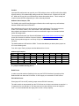
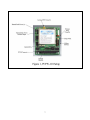
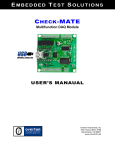
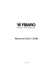
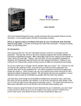
PCFW-104 M-Series Radio Modem
PC/104 Interface User’s Manual
MICROBEE SYSTEMS CORPORATION
9414 Danese Lane SE
Huntsville, AL 35803
Tech. Support: 256–426–2431
www.microbee-systems.com
[email protected]
COPYRIGHT 2002 MicroBee Systems Corporation.
All rights reserved.
However, any part of this document may be reproduced, provided that MicroBee Systems
Corporation is cited as the source. The contents of this manual and the specifications herein may
change without notice.
TRADEMARKS:
Windows® is a registered trademark of Microsoft Corporation.
ROM-DOS is a trademark of Datalight.
QNX is a trademark of QNX Software Systems, Ltd
1
NOTICE TO USER
The information contained in this manual is believed to be correct. However, MicroBee Systems
assumes no responsibility for any of the circuits described herein, conveys no license under any
patent or other right, and makes no representations that the circuits are free from patent
infringement. MicroBee Systems makes no representation or warranty that such applications will
be suitable for the use specified without further testing or modification.
MicroBee Systems Corporation general policy does not recommend the use of its products in life
support applications where the failure or malfunction of a component may directly threaten life or
injury. It is a Condition of Sale that the user of MicroBee Systems products in life support
applications assumes the risk of such use and indemnifies MicroBee Systems against all
damage.
Please read before installing your product.
MicroBee’s products are designed to be high in performance while consuming very little power. In
order to maintain this advantage, CMOS circuitry is used. CMOS chips have specific needs and
some special requirements that the user must be aware of. Read the following to help avoid
damage to your card from the use of CMOS chips.
Using CMOS Circuitry
Industrial Control originally used LSTTL circuits. Because many PC components are used in
laptop computers, IC manufacturers are exclusively using CMOS technology. Both TTL and
CMOS have failure mechanisms, but they are different. This section describes some of the
common failures which are common to all manufacturers of CMOS equipment.
Improper power causes catastrophic failure.
If a card has had reverse polarity or high voltage applied, replacing a failed component is not an
adequate fix. Other components probably have been partially damaged or a failure mechanism
has been induced. Therefore, a failure will probably occur in the future. For such cards, MicroBee
highly recommends that these cards be replaced.
Other over-voltage symptoms
In over-voltage situations, the programmable logic devices, EPROM’s and CPU chips, usually fail
in this order. The failed device may be hot to the touch. It is usually the case that only one IC will
be overheated at a time.
Power sequencing
The possibility of failure can be caused by the external application of input voltage to the radio via
the external B+ input while the PCFW-104 power is off. If you apply 5V to the input of a TTL chip
with the power off, nothing will happen. Applying a 5V input to a CMOS card will cause the
current to flow through the input and out the 5V power pin. This current attempts to power up the
card. Most inputs are rated at 25 mA maximum. When this is exceeded, the chip may be
damaged.
Failure on power-up
Even when there is not enough current to destroy an input described above, the chip may be
destroyed when the power to the card is applied. This is due to the fact that the input current
biases the IC so that it acts as a forward biased diode on power-up. This type of failure is typical
on serial interface chips.
Hot insertion
Plugging cards into the card cage with the power on will usually not cause a problem. (MicroBee
urges that you do not do this!)
However, the card may be damaged if the right sequence of pins contacts as the card is pushed
into the socket. This usually damages bus driver chips and they may become hot when the power
is applied. This is one of the most common failures of expansion cards.
2
PREFACE
This manual is a guide to the proper configuration, installation, and operation of your PCFW-104
Interface. For setup and operation of the FreeWave FGRM Radio Modem refer to the FreeWave
Radio Users Manuals included with this product. You can use your PCFW-104 card in
conjunction with other PC/104 expansion cards, tailoring your system for a wide variety of
applications.
TECHNICAL SUPPORT
MicroBee Systems is committed to supporting our products. For this reason all FreeWave User
manuals as well as this manual are always available online in PDF format at
http://www.microbee-systems.com/user_manuals.htm.
This unit has been tested with a number of operating systems including MSDOS, Linux, QNX,
Microsoft Windows 98, NT and 2000. Any operating systems supporting an ISA legacy device
should operate normally with this product. MicroBee Systems does not guarantee operation with
unusual or custom operating systems.
If you have a question about the PCFW-104 card and cannot find the answer in this manual, call
Technical Support. They will be ready to give you the assistance you need.
•
•
•
When you call, please have the following at hand:
Your PCFW-104 Radio Modem Interface User’s Manual and the FreeWave Radio Users
Manual.
A description of your problem.
The direct line to Technical Support is 256-426-2431.
OVERVIEW
The PCFW-104 PC/104 FreeWave Data Radio is a PC/104 Bus Compliant 8 BIT interface that
allows the FreeWave Model FGRM-511X005 900 MHz data radio to be easily installed on any
PC-104 stack.
The PCFW-001 is fully PC/104 compliant in all aspects EXCEPT height. The PC/104
specifications calls for a height of 0.4 inches. The unit exceeds the recommended height by
approximately 0.200 inch and is due to the RF Shield.
Once the unit is configured and installed it is treated like any other serial port on the stack. In
other words, if it is configured for an address of 3F8 and IRQ 4 then it is as simple as using any
device on COM 1.
The interface supports baud rates up to a maximum of 115,200.
The unit includes the 16 bit ISA connector so 16 bit devices can be placed on the stack after the
radio. Also interrupts 10, 11, 14 and 15 are accessed thru this connector. The PCFW-104, being
an 8 BIT interface, does not require a 16 bit ISA card be prior to the radio unless operation
requires IRQ 10, 11, 12 or 15.
For more information on the PC-104 ISA bus please refer to the PC-104 specification at:
http://www.pc1 04.org/technology/PDF /PC1 04Specv246.pdf
3
Operation
This unit is extremely easy to use and incorporates three jumper sets, JP1, JP2 and JP3.
The PCFW-104 contains static sensitive CMOS components. The greatest danger occurs when
the card is plugged into the PC/104 stack. The card becomes charged by the user and the static
discharges to the I/O bus from the pin closest to the card connector. If that pin happens to be an
input pin, even TTL inputs may be damaged. Follow sound ESD practices!!!!
To avoid damaging your card and its components:
1. Ground yourself before handling the PCFW-104 Radio Modem.
2. Disconnect power before removing or inserting the PCFW-104 Radio Modem.
OPERATING PRECAUTIONS
Be sure that your PC/104 stack and/or power supply has sufficient current to supply the radio at
the specified power setting. It is recommended that the supply have a minimum of 1.0 Amps for
the 12 VDC internal or 8-30 VDC external source.
TECHNICAL SPECIFICATIONS
Baud Rate
The PCFW-104 is fully 16C550A compliant and supports software selectable baud rates of 300,
1200, 2400, 4800, 9600, 19.2K, 38.4K, 56K and 115.2K.
Environmental
-40° to 85° C operating.
-50° to 90° C non-operating.
RH 5% to 95%, non-condensing.
Power Specification
5V +/– 5% at 50 mA max.
12V +/- 5% at 500 mA, Radio powered by PC/104 Bus.
8-30V at 500 mA, Radio powered from external source using J4
Size
3.6 in. x 3.8 in x 0.6 in.
91.4 mm X 96.5 mm x 15.2 mm
INSTALLATION
Before installing the PCFW-104 Radio Modem, refer to Figure 1 for the location of various
connectors and jumpers.
Interrupt Select Jumpers, JP1
JP1 is used to select the IRQ Level. IRQ's 3, 4,5,7, 10, 11, 14 and 15 are supported.
Simply select the desired IRQ level by moving the jumper to the appropriate position.
From left to right:
IRQ 15,14,11, 10, 7, 5, 4, 3. Default configuration is IRQ4 which is standard for COM1 & COM3.
4
Caution:
Improper IRQ configuration can result in your CPU locking up due to an IRQ conflict. Most COM
libraries allow for non-standard IRQ settings as will after market drivers. Windows 95, 98, ME,
NT, 2000 and XP may limit your IRQ selection without aftermarket drivers. This is usually not
required unless all IRQ’s supported by the OS are already allocated.
Address Select Jumpers, JP2
For flexibility with most SW and Development libraries this unit will support any valid address
between 0x000-0x007 and 0x7F8-0x7FF.
Most applications will use one of the common serial port addresses. The most common are:
COM1 = 3F8, IRQ4, COM2 = 2F8, IRQ3 COM3 = 3E8, IRQ4 COM4 = 2E8, IRQ3
Most software development libraries for serial communication support non-standard address
and/or IRQ assignments.
Two excellent libraries are from GreenLeaf Software at http://www.Qleaf.com/main.asp and
Comm-Drv Libraries from Willies Computer Software at http://www.wcscnet.com/
Both of these products support a vast array of high and low level RS-232 communications
functions.
The default address is 3E8 which is COM3. To select the address you desire place jumpers on
JP2 in the following order.
From left to right. Placing a jumper sets the address bit to 0 or low.
Addressing Examples:
Hex
A10
A9
2F8
X
300
X
310
X
3E8
X
3F8
X
7F8
A8
X
A7
A6
A5
A4
A3
X
X
X
X
X
X
X
X
X
X
X = jumper installed meaning bit = 0.
Radio Power
In order to provide maximum flexibility for the user the PCFW-104 allows for powering of the
Radio Module from either the PC/104 Bus 12 VDC supply or an external 6-30 VDC source.
PC/104 Bus Power:
Place jumper JP3 in the INT position (jumper nearest PC/104 Connector).
The radio module is now powered from the PC/104 bus an no further connections are required. It
is important to be sure that the 12 VDC bus power source has sufficient current to supply the
radio. It is recommended that the supply have at least 1.0 Amp capacity.
5
External Power:
Place jumper JP3 in the EXT position (jumper farthest from PC/104 Connector). The radio power
now comes from terminal block J4. Note polarity! The positive terminal is marked with a + and is
the terminal farthest from the PC/104 Connector. Be sure to tighten the terminals snugly.
The radio can be powered from any 6-30 VDC source such as vehicle power as long as the
source is capable of at least 1 Amp.
Caution!
Observe polarity when powering radio from external power!
When using external power sources for the radio modem it is essential that the external
radio power and PC/104 stack be switched at the same time as described earlier in this
manual. It is recommended that if vehicle power is used the radio and PC/104 stack be
switched from the same master power switch. Powering the radio and not the stack could
potentially damage either the radio or the stack. Similarly, powering the stack and not the
radio can also potentially cause damage.
Setup Switch
In order to access the FreeWave Radio setup menus it is necessary to drive the setup line on the
radio low. This can be achieved two ways. One, the PCFW-104 incorporates a setup switch.
Pressing this switch while in a terminal program such as Hyper Terminal will invoke the user
setup menu and allow the radio to be configured for the users network.
Since the PCFW-104 is to be used in remote embedded applications inside a case Connector J5
is available to facilitate the installation of a external setup switch. Shorting the pins on J5 invokes
the user setup menu. Never apply power of any type to J5.
Testing Installation
NOTE:
Refer to the FreeWave Radio Users manuals for proper radio operation and setup.
Once the unit is installed it is recommended that the unit be tested using a simple
communications program such as Hyper Terminal under windows.
Open the communications program and select the proper COM port. Set the communications
parameters to 19,200 Baud, 8 Bits, No Parity, 1 Stop Bits (19200,N,8,1) and press the setup
button. The FreeWave Setup Menu should come up on the screen.
6
7
WARRANTY
MicroBee Systems Corporation (MicroBee), warrants that it’s standard hardware products will be
free from defects in materials and workmanship under normal use and service a period of one
year from date of purchase. MicroBee’s obligation under this warranty shall not begin until Buyer
returns the defective product, freight prepaid to MicroBee’s facility or another specified location.
MicroBee’s only responsibility under this warranty is, at its option, to replace or repair, free of
charge, any defective component part of such products.
LIMITATIONS ON WARRANTY
The warranty set forth above does not extend to and shall not apply to:
1. Products, including software, which have been repaired or altered by other than
MicroBee personnel, unless Buyer has properly altered or repaired the products in
accordance with procedures previously approved in writing by MicroBee.
2. Products which have been subject to power supply reversal, misuse, neglect, accident, or
improper installation.
3. The design, capability, capacity, or suitability for use of the Software. Software is licensed
on an ”AS IS” basis without warranty. The warranty and remedies set forth above are in
lieu of all other warranties expressed or implied, oral or written, either in fact or by
operation of law, statutory or otherwise, including warranties of merchantability and
fitness for a particular purpose, which MicroBee specifically disclaims.
4. MicroBee neither assumes nor authorizes any other liability in connection with the sale,
installation or use of its products. MicroBee shall have no liability for incidental or
consequential damages of any kind arising out of the sale, delay in delivery, installation,
or use of its products.
SERVICE POLICY
1. MicroBee’s goal is to ship your product within 10 working days of receipt.
2. If a product should fail during the warranty period, it will be repaired free of charge. For
out of warranty repairs, the customer will be invoiced for repair charges at current
standard labor and materials rates.
3. Customers that return products for repairs, within the warranty period, and the product is
found to be free of defect, may be liable for the minimum current repair charge.
RETURNING A PRODUCT FOR REPAIR
Upon determining that repair services are required, the customer must:
1. Obtain an RMA (Return Material Authorization) number from the Customer Service
Department, 256-426-2431.
2. If the request is for an out of warranty repair, a purchase order number or other
acceptable information must be supplied by the customer.
8
3. Include a list of problems encountered along with your name, address, telephone, and
RMA number.
4. Carefully package the product in an antistatic bag. (Failure to package in antistatic
material will VOID all warranties.) Then package in a safe container for shipping.
5. Write RMA number on the outside of the box.
NOTE:
For products under warranty, the customer pays for shipping to MicroBee. MicroBee pays for
shipping back to customer.
Other conditions and limitations may apply to international shipments.
NOTE:
PRODUCTS RETURNED TO MICROBEE FREIGHT COLLECT OR WITHOUT AN RMA
NUMBER CANNOT BE ACCEPTED AND WILL BE RETURNED FREIGHT COLLECT.
RETURNS:
There will be a 15% restocking charge on returned product that is unopened and unused, if
MicroBee accepts such a return. Returns will not be accepted 30 days after purchase. Opened
and/ or used products, non-standard products, software and printed materials are not returnable
without prior written agreement.
GOVERNING LAW:
This agreement is made in, governed by and shall be construed in accordance with the laws of
the State of Alabama.
The information in this manual is provided for reference only. MicroBee Systems does not
assume any liability arising out of the application or use of the information or products described
in this manual.
This manual may contain or reference information and products protected by copyrights or
patents. No license is conveyed under the rights of MicroBee Systems or others.
9