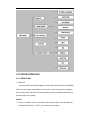
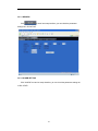
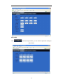
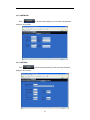
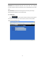
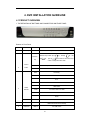
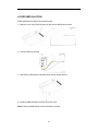
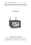
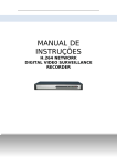
1
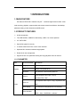
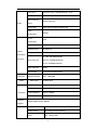
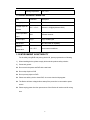
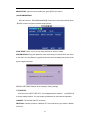
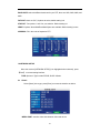
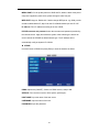
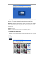
H.264 NETWORK Embeded DVR USER MANUAL 1 CONTENT 1 INTRODUCTION ..............................................................................................................3 1.1MAIN FEATURE ...........................................................................................................3 1.2 PRODUCT FEATURES...............................................................................................3 1.2.1 PARAMETER..........................................................................................................3 1.2.2 BASIC WORKING PARAMETER ...........................................................................5 1.3 ENTIRONMENT ADAPTABILITY................................................................................5 2. DEVICE OPERATION MANUAL.....................................................................................6 2.1 REMOTE KEY INSTRUCTION....................................................................................6 2.1.1 REMOTE CONTROL(OPTIONAL) .........................................................................6 2.1.2 MOUSE OPERATION(OPTIONAL)........................................................................7 2.1.3 MENU TREE ...........................................................................................................8 2.2 SYSTEM OPERATION................................................................................................9 2.2.1 USER LOGIN ..........................................................................................................9 2.2.2 GUI OPERATION..................................................................................................10 3. IE OPERATION .............................................................................................................27 3.1 FEATURE ..................................................................................................................27 3.2 USER LOGIN.............................................................................................................27 3.3 OPERATION INTERFACE ........................................................................................28 3.3.1 LIVE.......................................................................................................................28 3.3.2 REPALY ................................................................................................................29 3.3.3 SETUP ..................................................................................................................32 4. DVR INSTALLATION GUIDELINE................................................................................37 4.1 PRODUCT OVERVIEW.............................................................................................37 4.2 HDD INSTALLATION.................................................................................................40 5.FAQ.................................................................................................................................41 2 1 INTRODUCTION 1.1MAIN FEATURE 4/8 channel CIF/HD1/D1(8channel only CIF) resolution digital video recorder. It has local recording, playback, support treble code remote network surveillance, data backup, parameter setting, motion detection and USB mouse. 1.2 PRODUCT FEATURES H.264 compression Two USB interface, USB2.0 for data backup, USB1.1 for mouse operation. 3.5” SATA HDD. Special file system for security. 16 nature translucence GUI, note for menu selected Optimized four channel simultaneously playback Double level user management Support the live view, parameter setting and copy playback video via network. 1.2.1 PARAMETER Item System Device Parameter Specification Language Chinese/English GUI Graphic menu(OSD Menu) password user password, administrator password Video in Video Video out Video display Video standard 4/8ch composite video input 1.0Vp-p, impedance75Ω,BNC 2ch composite video output 1.0Vp-p,impedance75Ω, BNC 4ch:1/4channel switch(8channel:1/4/9 channel ) PAL,25f/s,CCIR625line,50scene NTSC,30f/s,CCIR525line,60scene 3 Audio input 4/8ch audio input,impedance600Ω,RCA Audio output 1ch audio output,impedance600Ω,RCA Basic electricity Audio output Record style Audio compression Picture compression Picture Audio video recorded simultaneously ADPCM H.264 Picture resolution CIF/HD1/D1(8channel only CIF) Streaming style ISO14496-10 Audio style ADPCM proceeding and store Linearity electricity CIF: 384~768 Kbps(optional) Video code rate HD1:512~1024Kbps(optional) D1:512~1024Kbps(optional) Connector Alarm Audio code rate 32KB/s Data storage SATA HDD storage(optional) Network interface RJ45,10M/100M Alarm input 4/8 alarm input Alarm output 1 alarm output Serial interface Connector Software upgrade others Support 1 RS232 Serial interface Support 1 RS485 Network interface RJ45,10M/100M Support USB firmware upgrade voltage input AC:110~240V Voltage output DC: [email protected]/(3A optional ) Power 6W without HDD 4 Working temperature -10----50℃ 1.2.2 BASIC WORKING PARAMETER Item Parameter description Voltage input 19V DC 19V 12V(+/-0.2) 4channel :12V@2A(8channel W/O) 75Ω 75Ωeach channel。 1Vp-p 1Vp-p CVBS signal Voltage output for camera Video impedance input Video output SATA HDD Working temperature One SATA with all capability -10----50℃ Under normal conditions 1.3 ENTIRONMENT ADAPTABILITY For the safely using DVR and prolong device life, please pay attention on following 1) When installing device, please comply all the electric product safety criterion; 2) Power and ground: Do not touch the power and DVR with a wet hand Do not drop liquid on DVR Do not put any object on DVR Please use soft dry cloth to clean DVR; do not use chemical impregnant. The Device will have voltage before startup if the power line is connected to power source. Please unplug power line from power source if the Device will not be used for a long time. 5 2. DEVICE OPERATION MANUAL In device operation, the enter key on remote control has the same function as left click of the mouse. 2.1 REMOTE KEY INSTRUCTION 2.1.1 REMOTE CONTROL Handheld IR Controller Key Functions: 【0-9】keys: During setup, number keys are used to input values. For viewing channels 1, 2, 3 and 4, use 1, 2, 3 and 4 on numeric keypad respectively. , : Up, Down directional keys: Move selection up and down in setup menu. , : Left, Right directional keys: Move cursor left or right in setup menu. 【QUAD】: Switch 4 Channels; 【FWD】: Fast forward the video while playback. press 【PLAY】to return to normal speed; 【REV】: Reverse the video while playback, press REW to switch, press【PLAY】 to return to normal speed; 【POWER ON】: Reset the MDVR to Power on and Power off mode. (standby and start up); 【LOGIN/LOCK】: If the security is enabled in the setup, use LOGIN/LOCK key to enter the user setup. It is important to remember the password due to without restoration function. Log in(to enter into “User ID select” and “Password” input interface)and lock functions(To exit setup and operation) 【OSD】: Press OSD for main menu; 【PTZ】: PTZ control,press this key to enter into PTZ control interface when at single live view; 6 【EXIT】: Exit to the preview or return to the last menu; 【RECORD】: Start manual record 【STOP】: Stop manual record 【ASISTANT】For future use 2.1.2 MOUSE OPERATION You can use mouse to make operation of the menu besides IR remote controller. (The operation is the same as PC Windows).Please inserts the mouse into USB 1.1. Enter into main menu: Click the right key on the live view. Click Exit the present menu: It will not save the settings if clicking the right key to right key exit. Exit the playback interface: Click the right key to exit during playback. Click left key Click the left key to enter into the setting interface. Click the left key to zoom in the window on the live view and playback video. Double click the left key will exit to the live view and playback multi-window interface. 1. Volume adjustment, color adjustment setting. It is for setting the single channel for volume adjustment and color adjustment. If it is multi-window, please use the left key to select the single window. 2. The remark when click the left key for volume adjustment, color adjustment is as follow: a.There is a sticker to show the volume on the volume adjustment interface. Move the mouse to the corresponding position and click the left key. The right side of sticker will show the volume ,click “x” to exit. b.Color adjustment can refer to the volume adjustment interface operation. When there are many options in the option frame, click left key to see down-pull menu. 7 Click the left key on the playback interface can make >> forward function, << rew function, >>I Slow play function, I> frame play function,> Play function, X exit function. 1. In the input frame, click the left key can activate the keyboard. The number, symbol, English can be input by clicking the mouse. 2. Pinyin also can be input by the soft keyboard when enter Chinese, the Click left method is the same as remote control. You can use the left/right key to turn key over the page when check on Pinyin/Chinese word. 3. When input number, click the right key, the number soft keyboard will bob up firstly, and then use the left key to select the corresponding numerical value. Also click the left key to exit the number keyboard. 1. Press the left key to move the mouse can adjust the parameter on the Mouse move volume, color interface. And the corresponding parameter will be display at the same time. 2. In the Motion Detection setting interface, you can use the left key to drag the frame to set the motion detection area. 2.1.3 MENU TREE You can control the DVR by the menu operation. The following tree diagram shows the menu structure and more details will be shown in next chapter. 8 2.2 SYSTEM OPERATION 2.2.1 USER LOGIN 1. START-UP Connect the DC19V/3.42A(3A) adapter to DVR. When start up the DVR,【POW】LED will be on and 4 images will be display on the screen. If it has setup ignition recording or time recording, the system will record automatically and the corresponding LED will be on, and the system work normally. Remark: 1) If there is no HDD in device, or the device didn’t read the HDD, or the HDD didn’t be formatted it will display an 【H】 in the video preview interface. 9 2) You must format the HDD in the DVR before first using. The steps as follows: menu > HDD management > format. After formatting, the system will restart. 2. SYSTEM LOGIN You can login from the USER LOGIN window as follow. Input device ID and user password via numeric key-board. You can access to main menu by pressing 【Apply】if the password is enabled. Remark: Default device ID is: 00000, user password is 000000 and Admin password is 020818. For your convenience and system safety, you can setup the user password and change the device ID in the Setup. Administrator has all authorities, while operator has limited authorities to only watch and playback.: Device ID: You just need to enter the device ID as the right frame. Password: enter the admin password or user password. 2.2.2 GUI OPERATION The main menu include “SEARCH”,”RECORD”,”HDD”,”BASIC”,“ADVANCE”, and “Exit”. 10 Remark: To make the setting of submenu valid, you must press “APPLY”. It will not be workable if exit directly. This DVR has a special feature: Explanation and information will be showed automatically when you move the cursor on the Menu. 1 RECORD SEARCH Move the cursor to 【RECORD SEARCH】(Icon highlighted when selected),press 【Enter】to enter into the setting interface. There are three methods of searching record. Method 1: playback by date Date input: You can adjust the checking date and time, press【Enter】or input the number directly to adjust the year, month, date. And then input time in the next box, click “play” and then you can see the recording video. Method 2: playback by recording status: Input the date, click 【search】 and you can see the recording status on this date. Instruction: 1. MONTH: It will show all the recording status in this month. Green means normal recording, Red means alarm recording, Grounding means no recording. Click any date in this frame will search the recording status of that day, the searching result will be showed in the below date frame.. DATE: I t will show all the recording status in this day, you can playback the recorded files in any period by clicking the corresponding period. Method 3: playback by file list: Input the searching date, click “SERACH” and you can see the recording status. Click 11 an exact day and then click “detail file” and then you can see the interface of “detail file”. CHANNEL: There are CH1, CH2, CH3, CH4 and QUAD, totally 5 options. Press 【Enter】and you can change the channel to be displayed. TYPE: There are all, normal and alarm, totally 3 options. Press【Enter】and the content will be displayed in a list. Instruction: 1. 【FILE LIST】,“CHANNEL” is the recording file belongs to the corresponding channel, “SIZE” is the displaying size of this file(Unit:MB),“TYPE” is the displaying type of the recording file : there are two types: normal and alarm. Pressing “BACKUP” button will export the selected files to USB storage; 2. After moving the cursor up and down and selecting the files, press【APPLY】to enter into playback interface。f all channels have recording files, it will playback all windows at the same time; 3. If setup as “on” in the【RECORD TIME】in 【BASIC SETUP】,it will show the date/time when playing back recorded file;If setup as “off” it will not display time; 4. During playback, press【SLOW】to play slowly;press【FORWARD】、 【REVERSE】 to speed、reverse play; press【PAUSE/STEP】to pause and frame by frame play; press【Exit】to exit from playback and return to the former menu; 5. When playback files finish, it will return to the file list interface 2 BACKUP You can use USB for backup by inserting USB device into the USB2.0 port before backing up files. It also supports USB OTG 12 You can select the recording file by direction keys, press【Enter】means the selected is confirmed(There is a “√” at the end of the selected recording files), press 【Enter】again the “√” will disappear which means the selected is cancelled. You can start export the selected recording files by pressing【BACKUP】, as follow: Instruction: 1. When the space in backup device is less than recording file, the system will prompt “Space not enough”.. 2. You can remove USB device directly when backup is finished 3 RECORD MODE Move the cursor to 【RECORD】(Icon highlighted when selected). Press【Enter】 to enter the setting interface. Press【Confirm】and enter the setup interface. You can use direction keys and cursor to change the options. CHANNEL: ON: Means the channel enabled for record RESOLUTION(Only 4CH): Setup resolution and code rate for recording, there are three 13 options: HIGHEST,HIGH, NORMAL, corresponding to D1、HD1、CIF resolution. QUALITY : There are three options: BEST, FINE AND NORMAL, corresponding to HIGHEST,HIGH AND NORMAL data stream standard AUDIO: ON: Means enable the audio recording for all channels, OFF: Means audio recording is disabled REC.MODE POWER UP: Means the device will start recording when it starts up TIME: Recording as scheduled; you can setup schedule as you want as follow. CHANNEL: You can select all channels or just one channel(Blue means selected) DAILY:There are three modes: ALARM, NORMAL, NO REC. If you select one mode, the whole day will be recorded at that mode. You can cancel recording by pressing【Enter】 button; grounding means do not record, different color means different record mode: Red means alarm record, Green means normal record, grounding means no record. RECORD SIZE:There are 15min, 30min, 45min, 60min four options; it will pack as the mode you selected. Scroll to APPLY and press ENTER to save the new settings. 4 HDD MANAGEMENT. Move the cursor to 【HDD】 (Icon highlighted when selected), press【Enter】to enter into the setting interface, and you can use direction keys or cursor to change the options. 14 HDD STATUS:There are three status available, normal, un-format, No HDD. If HDD cannot run normally(including unformat and no HDD), there will be a 【H】displayed on video live view. OVERWRITE:ENABLE: when HDD space is less than 4G, it will delete earliest recording files, and it will stop deleting when the space is 10G; DISABLE:when HDD space is less than 500M it will stop recording, and a prompt will display in live view: “please shutdown and replace HDD”. FORMAT:Move cursor to select device and press【APPLY】 to start formatting. 5 BASIC SETUP Move cursor to select “BASIC SETUP” (The big icon means select ok)and press 【ENTER】to enter into the system language setup interface. Basic setup includes system language, time/date, password security, display, video/audio and exit. 15 6 SYSTEM LANGUAGE SETUP Move cursor to select “system language” (The big icon means select ok)and press 【ENTER】to enter into the system language setup interface. System language is optional, including Chinese and English. You can choose the language you want. Remark: The device will restart when you finish system language setup. 7 DATA/TIME SETUP Move cursor to select “date/time” (The big icon means select ok)and press【ENTER】 to enter into the date/time setup interface. DATE: Setup system date via numeric key. DATE FORMAT: Press ENTER to switch the date patterns: there are YY-MM-DD and MM/DD/YY for your selection. TIME: Setup system time via numeric key. 16 TIME FORMAT: Press ENTER to switch the time patterns; there are 12 HOURS and 24 HOURS for your selection. Remark: You must press 【APPLY】 to save after you modify the time and date, modification will not be saved if you exit directly. DST: Still under construction. 8 PASSWORD Move the cursor to【PASSWORD】(Icon highlighted when selected), press【Enter】 to enter into the setting interface. DEVICE ID: Press number key to setup the ID PASSWORD: Press【APPLY】 to start or close the user password. If it is “ENABLE”, you have to input password when login, otherwise, you can access main menu directly. USER PASSWORD: Press number key to setup. ADMIN PASSWORD: Press number key to setup. NETWORK PW CLEAN:select and apply will initialize the IE browser password . 9 DISPLAY SETUP Move the cursor to【BASIC SETUP】 (Icon highlighted when selected), press【Enter】 to enter into the setting interface. 17 NAME: press【Enter】to enter into the setting interface. POSITION: Name location is optional. You can press 【Enter】to switch from bottom left, top left, bottom right, top right and OFF. COLOR: press【Enter】to enter into setting interface as follow: Press【Enter】or【+】【-】key or directly drag the cursor to setup colors, including chroma, brightness, contrast and saturation, press【APPLY】to save the parameters once the setup is completed. PREVIEW:ON: Means the channel is allowed to view the live mode, OFF means not. PREVIEW TIME: ON: Means insert clock in live view, OFF means not. RECORD TIME :ON: Means insert clock in record file, OFF means not. 10 VIDEO/AUDIO SETUP Move the cursor to【VIDEO/AUDIO SETUP】(Icon highlighted when selected), press【Enter】to enter into setting interface. 18 VGA RESOLUTION:1024*768,800*600 CAMERA SYSTEM: press【Enter】to select camera system: PAL or NTSC . VOLUME SETUP: move cursor to【VOLUME SETUP】,then press【Enter】to access volume setup interface, press【+】【-】or number keys or directly drag the cursor to adjust the volume. 11 ADVANCE SETUP Move the cursor to【ADVANCE SETUP】(Icon highlighted when selected),press 【Enter】to enter into setting interface. Picture is below: Advanced Function includes Alarm settings, system information, Motion detection, mobile phone monitoring, system maintenance, PTZ and network setting. 12 ALARM SETUP Move the cursor to【ALARM SETUP】 (Icon highlighted when selected),press 19 【Enter】to access setting interface. I/O CHANNEL: Each channel corresponds an I/O status, which means when an alarm is triggered, it will activate the corresponding channel to start alarm recording. N.O:indicate I / O input level from high to low N.C:indicate I / O input level from low to high HDD LOSS:ON: means it will trigger an alarm if there is no HDD, and a 【H】will be displayed on the left bottom of channel 1 in the live view HDD SPACE:ON:If the space is less than 500M, a remark will appear in live view:Not enough space, please change HDD after shutdown. VIDEO LOSS:ON: when one channel has no video input, it will display “video loss” in live view. ALARM MANAGE: Includes three options, alarm output, buzzer and post REC.OUTPUT:When an alarm is triggered, the alarm output time will be:0 second、10 seconds, 20 seconds, 40 seconds and 60 seconds BUZZER:Buzzer calling time setup when alarm is triggered: 0 second,10 seconds,20 seconds,40 seconds and 60 seconds POST REC.:Post recording time setup: 30 seconds,1 minute,2 minutes and 5 minutes PRE REC:Pre-recording time is fixed as10 seconds 20 13 SYSTEM INFO Move the cursor to【SYSTEM INFO】 (Icon highlighted when selected),press【Enter】 to access setting interface. This interface includes : firmware version, MAC address, serial number. 14 MOTION DETECT Move the cursor to【MOTION DETECT】 (Icon highlighted when selected),press【Enter】 to access setting interface. STATUS:Each channel has corresponding channel switch, press 【Enter】to turn on or turn off the motion detection for each channel. SENSITIVITY:each channel has corresponding sensitivity setting; including four standards: higher, high, medium and low, press【Enter】to switch. MD AREA: each channel has corresponding regional motion detecting setting, move the cursor to corresponding【setting】,press【Enter】to enter regional setting interface, red area means motion detection is activated, transparent block means motion detection is 21 not activated. Press the direction key on remote control to move cursor along the small pane: position of cursor is indicated by green frame. Press【Enter】to select or cancel motion detection of this small pane. When setup is finished, press【exit】to go back to MD setup interface and settings will be saved automatically Remark: IR Operation: press [Menu] key to select or cancel full screen. Mouse operation: click left and drag the frame to setup the region for motion detection. 15 MOBILE Move the cursor to【MOBLE】(Icon highlighted when selected),press【Enter】 to enter into setting interface. Picture is below: MOBILE NETWORK: Select different mobile network from the options of 3G, 2.5G and 2.75G; press [APPLY] to choose different network. 22 MOBILE PORT: Input the correct mobile port; press [APPLY] to confirm 16 SYSTEM MAINTAIN Move the cursor to 【SYSTEM MAINTAIN】(Frame turns red means selected), press 【Enter】to enter into system maintain setup interface. AUTO RESET: When it is on, you can setup the time for device to restart. SYSTEM UPDATE: Copy the update file to the root directory of a thumb driver, then insert it. into USB 1.0. Press [Enter] to upgrade the firmware and it will display the process of the system upgrade as follow: DEFAULT SETTINGS: Restore all the settings to factory settings. 17 PTZ SETUP Move the cursor to【PTZ SETUP】(Icon highlighted when selected),press【Enter】 to access setting interface. You can setup the parameters for each channel separately. CHANNEL: The channel with PTZ connected. PROTOCOL: select the protocol of different PTZ: two protocols for your selection. Default is Pelco-D 23 BAUD RATE: select the different baud rate for your PTZ, there are 1200, 2400, 4800, and 9600 DATA BIT: there are 5,6,7,8 options to select, default setting is 8. STOP BIT: Two options: 1 and 2 for you selection. Default setting is 1 VERIFY: Options: None/Odd/Even/Mark/Space are available. Default setting is none ADDRESS: Fill in the code of respective PTZ. 18 NETWORK SETUP Move the cursor to [NETWORK SETUP] (icon highlighted when selected), press 【Enter】 to access setting interface. TYPE: Options in Type include PPPOE, DHCP & Static. 1 Static Select [Static] in the type, press [Enter] to access the interface as below: MEDIA PORT: transfers video data between client and device. 24 WEB PORT: setup the port of IE browser via HTTP. IP ADDRESS: setup the IP address, and press [Enter] input numbers to fill IP address. NET MASK:. press [Enter] input numbers to fill net mask. GATEWAY: press [Enter] input numbers to fill default gateway. 2 DHCP Select the DHCP, and enter into the interface as follow. MEDIA PORT: same as static setup WEB PORT: same as static setup. NOTE: restart system when select DHCP, and it will automatically connect with DHCP server. Will allot IP address when connect ok and the address will showed on the interface. 3 PPPOE Select the PPPOE, and enter the interface as follow. 25 MEDIA PORT: Port for private protocol of DVR and PC, default : 9000. If this port of computer is applied by other server, please change to other free port. WEB PORT: Http port. Default: 80. If admin change WEB port to: e.g. 8088, port No. should be added behind IP, http://192.168.15.145:8088 should input into IP of IE. IP address: Fill in IP address according to the net of DVR; PPPOE username and password: enter the username and password provided by the internet service. Apply and reboot the system. After rebooting, the device will save it and set the PPPOE as default network type. The IP address will be automatically config as dynamic IP of WAN. 4 DDNS: move the cursor to DDNS and press [Enter] to enter the interface as follow: DDNS: Options are [ON/OFF]. If there is a DDNS service, setup to ON. SERVICE: Four services to select: 3322, dyndns, perfecteyes, . HOST NAME: Input the name of the host server. USERNAME: Input the name of the user. PASSWORD: Input the password. 26 3. IE OPERATION 3.1 FEATURE Install the software through the IE browser of OS and you operate the network remotely and conveniently. DVR supports C/S, B/S, and visit in LAN and WAN, also supports IP and domain name visiting. RESTRICTION CONDITION: To ensure PC‘s stable visiting of DVR, recommend Windows XP, Windows Vista operation system, recommend browser as IE 6.0, IE 7.0. 3.2 USER LOGIN Input the DVR local IP in IE browser, if the web port number is set as 80, directly input IP address into IE address column; If not 80, port number should add behind IP. E.g. when IP is 192.168.0.102, set port is 8088, http://192.168.0.102:8088 should input. When the net is connected, IE will automatically download the file to PC as following, The process will last for 1~2 minutes. Please click “If your browser does not support the ActiveX to download, please click here”when downloading not successful. System will automatically enter GUI as follows: 27 Select English interface from the top left side. Input username and password to enter the system. The username and passport are the same as the ones set in DVR. PASSWORD: Administrator has all authorities, operator has limited authorities who they can only watch, playback, please change the unit No. and default password in time for system security. NETWORK: LAN/WAN Remark: If you connect the device in WAN, the IP should be a public IP. 3.3 OPERATION INTERFACE Options in the main interface include Live View, Playback and Setup. Click any option to access. 3.3.1 LIVE Click to enter into the interface as follow 28 3.3.1.6 PLAY Move cursor to the icons, it will highlighted when selected Open all windows Capture picture, save in local disk, system save default route is C:/DVR Quick-start to record video on all channels. The left upper corner of each channel has normal recording video symbol 【R 】; click icon to switch between single screen /quad /nine /16 split . Volume adjust button 3.3.1.7 OTHER OPERATION 1. Select one channel at preview screen (the selected channel’s frame will be change to RED), double click left key, enter to the selected channel single screen display. 2. Click one Chanel via left key at preview screen, then click right key, will occur window shortcut Menu, see below picture You can open, shut down and start this channel’s record via shortcut menu. 3. Click right key at one live view screen, click” open all windows” or “ close all windows”, will quickly open/close all windows. 3.3.2 REPALY Click” REPLAY” to enter into playback interface. 29 Click right up of calendar interface and , to setup the month for searching; click ”REFRESH” at the calendar interface will display the recording information of current month. The highlighted date indicates video was recorded on that day. RED FRAME means the date is system date, click the date will search that days’ recording file list. For example, the above picture display 2008, Dec. 3rd,4th,5th,6th,8th,9th,10th,11th,12th,17th,18th have recorded video, and system date is 18th, Dec, 2008, current search date is 17th, Dec. Select channel and type at the bottom of the calendar. Click “SEARCH” and the result will display as follows:. 30 Double click one of the listed recorded video to playback. The file icon will change to , and the following picture will appear: The above purple progress bar shows download progress, green progress bar shows playback progress Switch between pause/play Stop play Fast play Slow play Pause at next frame Convert H.264 file to AVI file, click this button access into file convert setting interface, as follow. 31 SOURCE FILE: Click to setup the H.264 file to convert DESTINATION FILE: Click Click to choose the directory for saving the AVI file , after the setting and the file convert will start. The convert progress bar shown below will show the progress of convert 3.3.3 SETUP Click to enter into setup interface, this interface include record, alarm, PTZ, network, setting and system information six menus. 32 3.3.3.1 RECORD Click to enter into setup interface; you can check the parameter settings as in GUI of DVR. 3.3.3.2 ALARM SETTING Click “ALARM” to enter into setup interface; you can check the parameter settings as in GUI of DVR. 33 3.3.3.3 PTZ Click to access setup interface; you can check the parameter settings in GUI of DVR. 34 3.3.3.4 NETWORK Click to access setup interface; you can check the parameter settings in GUI of DVR. 3.3.3.5 SETTING Click to access setup interface; you can check the parameter settings in GUI of DVR 35 BANDWIDTH: Set the bandwidth in kbps (128k、192k、256k、384k、512k、1024k) that you want to allocate for traffic that matches the internet. This bandwidth does not include audio. FILE SAVE PATH: the save path of captured picture and recording video.IE login password and DST settings you can set as DVR setting. 3.3.3.6 HOST INFO Click to access system information interface (see below picture). This interface includes HDD status, remain record time, firmware version and MAC Address. All the information is fixed. 36 4. DVR INSTALLATION GUIDELINE 4.1 PRODUCT OVERVIEW 1. THE DEFINITION OF BOTTOMS AND CONNECTORS ON FRONT PANEL Buttons on Front Panel NO 1 TYPE Standby NAME Instruction STANDBY System standby button Direction key Control 2 OK direction key include: up【 【 】、 right 【 】、down【 】four buttons, which can move cursor to setup and control PTZ. Confirm operation/into PTZ control panel under live view button MUNE/EXIT Enter into main menu under live view, or exit sub menu REC Recording ALM Alarm ERR Error FULL On means the HDD is full. HDD HDD Status 100M On means network is 100M LINK On means network has connected POW Power IR receiver IR Remote control receiver 4 USB2.0 USB2.0 USB2.0 for thumb drive to backup 5 USBMOUSE USB1.0 For USB mouse 3 】、left Status indicator 37 2. THE DEFINITION OF BUTTONS AND CONNECTORS ON REAR PANEL Example:8channel Connectors on Rear Panel Item Physical connector Connector description 1 POWER input DC 19V/3.42A 2 Video output Two video output for connecting TV or monitor (BNC) 3 Video input For connecting analog video signal input (BNC) 4 Audio Input For connecting audio signal Alarm Input I/O alarm input, 4 for 4CH DVR and 8 for 8CH DVR Alarm Output I/O output for alarm RS485 RS 485 for connecting PTZ RS232 For connecting PC 5 +12V Power supply for DC relay and the current is 100MA (make sure short circuit can not happen) 6 Network For connecting Ethernet 7 VGA output Unavailable 8 USB2.0 Copy video record via USB2.0 9 Audio output For connection audio output 10 Fan Please check the fan function for diary maintained and change new one if the fan has some problems 38 5 SYSTEM NETWORK DIAGRAM Example:8channel 39 4.2 HDD INSTALLATION Please installation the HDD as the following steps: 1)Open the cover of the DVR and then you will see one HDD plate as follow. 2)Connect HDD line as follow 3)Affix HDD on HDD plate as indicated below with the screws around. 4)Install the HDD plate back into DVR and close cover . Notice: Newly installed HDD should format before recording. 40 5.FAQ If your problem is not listed below, please call our toll-free number for more support. 1. Question: DVR is not working after starting? Answer: Check the adaptor input Check the on-off power line, is it well-connected? Check the power on-off Check the upgrade procedure Check the main board of DVR 2. Question: DVR is rebooting automatically or stopped after starting the DVR for several minutes? Answer: Instability or low input voltage Bad track hard drive or the line of hard drive is bad On-off power supply is not enough The front-end video signal instability High temperature, too much dust, too bad the DVR operating environment The main board is not well-connected with other boards The hardware of DVR is defective 3. Question: No output of single channel, multi channel or all channel video? Answer: Please check the adaptor of camera whether to see if it is well-connected Please check the cable for connecting video input/output in the back panel of DVR Please insert the video source directly into the display device and check If they are causing the problem. Check the brightness of the picture and bring it back to its original default setting 41 No video input signal or too weak Display settings in the preview set to be closed The hardware of DVR is defective 4. Question: DVR cannot record after startup and the interface is showing "H" Answer: 5. Make sure power adaptor is DC 19V Make sure HDD is formatted Check the power and data connection cables of the HDD The HDD is defective The SATA port is not working Question: What is meaning of“R”“M”“I”“H” showed in interface? Answer: “R”means the channel is recording “M” means the channel is on motion detection “I”means the channel is on alarm “H” means there is either no HDD. the HDD is bad or the HDD is full 6. Question: DVR is having problem with real-time images, such as bad image color or serious brightness distortion Answer: If PAL and NTSC is not correctly selected on the BNC output, the images will be in black and white DVR is not compatible with monitor The video transmission distance is too far The setting of DVR color, brightness and so on are wrong 7. Question: No audio sound when monitoring? Answer: Check sound box or speaker functions. Also check possible short circuit. Audio source may be connected to the video channel. You can click to full-screen to check. The hardware of DVR is defective 42 8. Question: No audio sound when playing back? Answer: Setting problem: open audio-video item Check the audio to see if it is closed in playback interface 9. Question: System time is not correct? Answer: Wrong setting or user did not click "Edit" to confirm Battery is not connected properly Battery is dead. Please change. 10. Question: Why the “Stop recording” by the right mouse button does not work, how to stop recording? Answer: : The “Stop recording” by the right mouse button is only suitable for Manual recording. It can’t stop recording when it’s in “start recording” or the video in video plan. If you want to stop recording, please set the time is not recording. 11. Question: "Stop recording" function by the right mouse button does not work. How to stop recording? Answer: The "Stop recording" by the right mouse button is for Manual Recording only. It can not stop recording when it is in "start recording" or the video is in video plan. If you want to stop recording, please set the time to not recoding. 12. Question: Motion detection is not working? Answer: : The setting of motion detection area is not correct Sensitivity is too low 13. Question: CD-writer /USB backup error Answer: The data exceeds the capacity of backup device The backup device is incompatible 43 The backup device is damaged 14. Question: Remote control cannot work? Answer: : The address of remote control is not correct The distance of remote control is too far or the angle is too biased Remote control batteries run out Remote control is damaged or the front panel of DVR is damaged 15. Question: WEB cannot login? Answer: Please check the network to see if it is connected. Check if LINK or 100M LED is displayed normally on the panel; use ping xxx.xxx.xxx.xxx (DVR IP) to check if the Internet is linked properly. Recommended to use Windows XP or Vista operating system, also use IE6.0 browser or IE7.0 browser ActiveX control has been blocked. Please manually install ActiveX control again. Please install DX8.1 and upgrade your video card driver 16. Question: There is no picture or picture is not clear when you preview the recording or playback the recording via IE Answer: If you access DVR by IE, please choose "Wan" in "web environment" Please try "Close windows" by the right mouse button, and try "Open windows" again 17. Question: It displays "other members are setting......" while setting DVR by IE Answer: It probably means someone else is setting the DVR. Please check the DVR configuration interface or exit DVR. 44