1
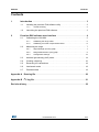
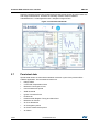
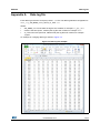
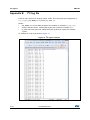
UM1764
User manual
VL6180X premium evaluation kit (EVK) software
Overview
The VL6180X proximity sensor premium EVK demonstrates the basic proximity, ranging
and light sensing capabilities of the VL6180X sensor.
The premium EVK software utility interfaces with the VL6180X proximity sensor premium
EVK to perform range, signal and ambient light measurements and display results in both
graphical and numerical form. Additionally, the utility provides the facility to configure and
calibrate the VL6180X device and provides comprehensive access to internal data for
diagnostic purposes.
The purpose of this user manual is to describe how to setup and use the premium EVK
software for evaluation, configuration and demonstration.
References
1.
VL6180X premium evaluation kit (EVK) hardware user manual (DocID024985)
2.
VL6180X datasheet (DocID026171)
Glossary
ALS
Ambient light sensor
EVK
Evaluation kit
I2C
Inter-integrated circuit serial communications interface
MCpS
Mega counts per second
NVM
Nonvolatile memory
P2P
Part-to-part
SNR
Signal to noise ratio
ToF
Time of flight
UI
User interface
VL6180X
Proximity sensor
X-talk
Cross-talk compensation factor
November 2014
DocID026336 Rev 4
1/23
www.st.com
1
UM1764
Contents
Contents
1
Introduction . . . . . . . . . . . . . . . . . . . . . . . . . . . . . . . . . . . . . . . . . . . . . . . . 3
1.1
Installing the premium EVK software utility . . . . . . . . . . . . . . . . . . . . . . . . 3
1.1.1
1.2
2
Trouble shooting . . . . . . . . . . . . . . . . . . . . . . . . . . . . . . . . . . . . . . . . . . . 3
Launching the premium EVK software . . . . . . . . . . . . . . . . . . . . . . . . . . . . 3
Premium EVK software user interface . . . . . . . . . . . . . . . . . . . . . . . . . . 4
2.1
2.2
Calibrating the VL6180X . . . . . . . . . . . . . . . . . . . . . . . . . . . . . . . . . . . . . . 5
2.1.1
Calibrating the range offset . . . . . . . . . . . . . . . . . . . . . . . . . . . . . . . . . . . 5
2.1.2
Calibrating cross-talk compensation factor . . . . . . . . . . . . . . . . . . . . . . . 6
Measuring the range . . . . . . . . . . . . . . . . . . . . . . . . . . . . . . . . . . . . . . . . . 7
2.2.1
Signal Strength (Power) graph . . . . . . . . . . . . . . . . . . . . . . . . . . . . . . . . . 7
2.2.2
Range Measurement (ToF) graph . . . . . . . . . . . . . . . . . . . . . . . . . . . . . . 9
2.2.3
Configuration settings . . . . . . . . . . . . . . . . . . . . . . . . . . . . . . . . . . . . . . 12
2.3
Ambient light sensing (ALS) mode . . . . . . . . . . . . . . . . . . . . . . . . . . . . . . 14
2.4
Creating a data log . . . . . . . . . . . . . . . . . . . . . . . . . . . . . . . . . . . . . . . . . . 16
2.5
Recording I2C transactions . . . . . . . . . . . . . . . . . . . . . . . . . . . . . . . . . . . 18
2.6
Interleaved mode . . . . . . . . . . . . . . . . . . . . . . . . . . . . . . . . . . . . . . . . . . . 18
2.7
Persistent data . . . . . . . . . . . . . . . . . . . . . . . . . . . . . . . . . . . . . . . . . . . . . 19
Appendix A Data log file. . . . . . . . . . . . . . . . . . . . . . . . . . . . . . . . . . . . . . . . . . . . . 20
Appendix B I2C log file . . . . . . . . . . . . . . . . . . . . . . . . . . . . . . . . . . . . . . . . . . . . . . 21
Revision history . . . . . . . . . . . . . . . . . . . . . . . . . . . . . . . . . . . . . . . . . . . . . . . . . . . . 22
DocID026336 Rev 4
2/23
2
Introduction
1
UM1764
Introduction
This document describes how to set up and use the VL6180X premium EVK software utility.
The premium EVK hardware is described in the VL6180X premium evaluation kit (EVK)
hardware user manual (DocID024985).
Figure 1. VL6180X premium evaluation kit (EVK)
1.1
Installing the premium EVK software utility
The premium EVK software utility is available from
http://www.st.com/web/catalog/tools/FM147/SC1870/PF260779 .
Double-click on the setup.exe application and then follow the on-screen instructions to
install the VL6180X premium EVK software utility.
Minimum installation requirement is Windows XP (SP3).
1.1.1
Trouble shooting
If an installation fails, the user should ensure that any previous installations are removed as
follows:
- Select “Start Menu − Control Panel - Programs and Features”
- Locate any entries of VL6180X premium EVK and uninstall (Select Right Click - Change Next - Remove)
then attempt the installation again.
1.2
Launching the premium EVK software
To launch the premium EVK software utility, double click on the VL6180X EVK 1-04 shortcut
created on the desktop.
3/23
DocID026336 Rev 4
UM1764
2
Premium EVK software user interface
Premium EVK software user interface
When the premium EVK software is launched, the Ranging tab is displayed containing the
ranging mode interface as shown in Figure 2.
The ranging mode interface consists of two graphs, Signal Strength (Power) and Range
Measurement (ToF) (where ToF is short for Time of Flight).
To use the software, place a target above the VL6180X premium EVK hardware and click on
Start. The device begins ranging and the Signal Strength and Range Measurement
graphs will display data in real-time and numerically in the boxes to the right.
Note:
The true range may be incorrect until the device has been calibrated (see Section 2.1).
Figure 2. Ranging mode interface
The premium EVK software contains several tabs that can be used to display, calibrate and
configure various features of the premium EVK. The available tabs are:
•
Calibration, see Section 2.1
•
Ranging, see Section 2.2
•
ALS, see Section 2.3
•
Data Log, see Section 2.4
•
I2C Log, see Section 2.5
•
Interleaved, see Section 2.6
•
About - this tab provides a summary of the premium EVK software
DocID026336 Rev 4
4/23
21
Premium EVK software user interface
2.1
UM1764
Calibrating the VL6180X
In order to get accurate readings, the user may be required to calibrate the VL6180X range
offset and the cross-talk compensation factor. This is carried out in the Calibration tab.
Note:
To move from the Ranging tab to the Calibration tab, the VL6180X must stop ranging.
2.1.1
Calibrating the range offset
The VL6180X device requires a unique part-to-part range offset correction. The default
programmed value may be correct, however it may be required for the user to override this
and apply a different setting.
To calibrate the range offset use the calibration tool delivered with the VL6180X premium
evaluation kit and described in the VL6180X premium evaluation kit (EVK) hardware user
manual (UM1651). The resultant offset is added to the raw range: R0 = Rr + offset, where R0
is the offset range and Rr is the raw range in mm, see Figure 3.
If there is a glass in front of the VL6180X device a unique cross-talk compensation factor
must be determined and applied. If the glass configuration is altered in any manner, a new
cross-talk compensation factor must be determined.
Measured range
Figure 3. Range offset
Offset
Actual range
The factory calibrated NVM offset is used by default. Manual calibration is only required if
the offset is incorrect, resulting in incorrect range measurements.
To activate the automatic offset calibration, tick the Offset Override check box (this will turn
yellow), then click the Apply button. The Cal Offset button will now become available (see
Figure 4), follow the on-screen instructions to complete the calibration.
To manually apply offset calibration, enter the offset value in the Range Offset (mm) field
(after ticking the Offset Override check box) and click on Apply.
5/23
DocID026336 Rev 4
UM1764
Premium EVK software user interface
Figure 4. Offset calibration
Calibrating cross-talk compensation factor
The glass in front of the VL6180X device introduces stray light, also known as cross-talk,
where a proportion of the emitter output is reflected back to the receiver. This distorts the
range measurement but can be corrected by applying cross-talk compensation.
If there is glass in front of the VL6180X device a unique cross-talk compensation factor must
be determined and applied. If the glass configuration is altered in any manner, a new crosstalk compensation factor must be determined.
Figure 5. cross-talk compensation factor
Measured range
2.1.2
cross-talk
compensation
Actual range
DocID026336 Rev 4
6/23
21
Premium EVK software user interface
UM1764
The cross-talk compensation factor (x-talk) is calibrated with the premium EVK using a
target of approximately 3% (black) reflectance, at least 60 x 60 mm square, placed 100 mm
above the sensor.
To activate automatic x-talk calibration, click on the pink Cal x-talk button, follow the onscreen instructions then click Apply. Once calibrated the button will turn green.
To manually set the x-talk, enter the x-talk value in the cross-talk compensation factor
field and click on Apply as shown in Figure 4.
2.2
Measuring the range
When the premium EVK software is in ranging mode, it measures absolute range from the
sensor to a target. This is shown in graphical form in the Ranging tab, see Figure 2.
The Ranging tab displays two graphs:
•
Signal Strength (Power), see Section 2.2.1
•
Range Measurement (ToF), see Section 2.2.2
The buttons listed in Table 1 are available at the bottom of the tab.
Table 1. Buttons in the Ranging tab
Button
2.2.1
Description
Start (Pause/Resume)
Click on Start to begin ranging. The Start button changes to
Pause/Resume while the device is ranging.
Stop
Click on Stop to stop ranging.
Reset
The Reset button resets the I2C communications interface between the
application and the VL6180X.
HW Reset
The HW Reset button resets the VL6180X hardware.
Reset Stats
The Reset Stats button clears the measurement statistics Max, Min, Mean
and Std Dev values.
Configure
The Configure button displays the Configuration dialog which allows the
user to configure key parameters and initialization settings (see
Section 2.2.3).
Signal Strength (Power) graph
The Signal Strength (Power) graph plots, in real time, the Signal Rate (Mega Counts per
Second) returned from the target, as shown in Figure 6.
The Signal Rate can be viewed as a measure of the reflectance of the target, with high
reflectance targets producing stronger signal rates.
7/23
DocID026336 Rev 4
UM1764
Premium EVK software user interface
Figure 6. Signal Strength (Power) graph
To the right of and below the Signal Strength graph the information described in Table 2 is
displayed.
Table 2. Signal Strength information
Field
Description
Rtn Signal Rate
(MCpS)
Number of ToF pixel counts per second on the return array.
Rtn Amb Rate (MCpS)
Number of ToF pixel counts per second due to ambient light on the return
array.
Rtn Conv Time (µs)
The time required to reach the convergence threshold on the return array.
SNR
Ratio of signal rate: ambient rate. A minimum SNR threshold can be set
using the Configuration dialog (see Section 2.2.3) below which a range
measurement is rejected. The SNR threshold is typically set in the range
0.1 to 0.3.
Ref Signal Rate
(MCpS)
Number of ToF pixel counts per second on the reference array.
Ref Amb Rate (MCpS)
Number of ToF pixel counts per second due to ambient light on the
reference array.
Ref Conv Time (µs)
The time required to reach the convergence threshold on the reference
array.
Sampling Rate (Hz)
Number of samples captured per second. The premium EVK software can
use single-shot (default) or continuous ranging mode. Sampling rate is PC
dependent.
Error Status
If there is an ranging error, the range result error code will be displayed
here, as defined in the data sheet: Address 0x04D.
Tuning Settings
Displays the tuning settings file applied to override default settings.
DocID026336 Rev 4
8/23
21
Premium EVK software user interface
2.2.2
UM1764
Range Measurement (ToF) graph
The Range Measurement (ToF) graph plots, in real time, range measurements (see
Figure 7). The maximum range is 255 mm. The vertical axis can be changed using the
Configuration dialog (see Section 2.2.3). If a target is not detected, the maximum range is
displayed.
Note:
The graph default is 255mm. True Range shows the correct numerical range and this may
exceed the graph limits.
Figure 7. Range Measurement graph
The VL6180X premium EVK can be run in single-shot ranging mode (default) or continuous
ranging mode (by ticking the Continual check box). If in Continual ranging mode the time
between measurements can be changed using the Configuration dialog (see
Section 2.2.3).
The Range Measurement (ToF) graph can be changed to show threshold information, see
Range Management (ToF) graph showing thresholds.
To the right of and above the Range Measurement (ToF) graph, the information described
in Table 3 is displayed.
9/23
DocID026336 Rev 4
UM1764
Premium EVK software user interface
Table 3. Range Measurement information
Field
Description
True Range (mm)
This reports the measured distance of a detected target (includes offset
and x-talk).
Raw Range (mm)
This is the range measurement prior to applying cross-talk compensation
(but includes offset).
Max, Min, Mean,
Std Dev (mm)
These are post-processed measurement statistics to make noise
evaluation easier to characterize. The max, min and mean are the range
data measured by the sensor over 100 measured sample points.
Range Offset
This is a fixed offset parameter, unique to each part, which gets applied as
part of the range measurement algorithm. This parameter must be
determined for each part using the calibration procedure detailed in
Section 2.1: Calibrating the VL6180X.
Cross-Talk
compensation factor
This parameter gets applied as part of the range measurement algorithm.
It must be determined for each different air gap/glass using the calibration
procedure detailed in Section 2.1: Calibrating the VL6180X.
Max Convergence
(ms)
This is the maximum time allowed for a range measurement to be made.
No range output is given if the system has not converged within the
specified time (that is, no target or target out of range).
SNR Threshold
In high ambient conditions, range accuracy can be impaired. The SNR limit
is used to invalidate range measurements where the signal: ambient ratio
is too low. The SNR threshold defines the signal-to-noise threshold, below
which the range data is unreliable.
Continual
Changes ranging mode from single-shot to continuous mode
Thresholding
Check this box to enable upper/lower thresholds (defaults are 70 mm and
60 mm, see Section 2.2.3).
When enabled, these threshold lines are shown in the Range
Measurement graph. See “Range Management (ToF) graph showing
thresholds”.
Range Management (ToF) graph showing thresholds
The thresholding feature allows the user to define upper and lower limits and be alerted as
the range measurements transition across these limits by the display changing colour.
Figure 8 shows an example of the Range Management (ToF) graph with thresholding
enabled. It shows a minimum threshold of 60 mm, a maximum threshold of 70 mm and a
range measurement of 50 mm.
If the range measurement goes below the lower threshold the graph turns green. If it goes
above the upper threshold the graph turns pink. The graph will stay pink/green, till the
lower/upper threshold is crossed.
Thresholding is enabled by checking the Thresholding check box (see Table 3) and the
upper and lower threshold settings can be modified in the Configuration dialog (see
Section 2.2.3).
DocID026336 Rev 4
10/23
21
Premium EVK software user interface
UM1764
Figure 8. Range Measurement graph showing thresholds
11/23
DocID026336 Rev 4
UM1764
2.2.3
Premium EVK software user interface
Configuration settings
The Configuration dialog allows the user to configure key parameters and initialization
settings.
To access the Configuration dialog, click on the Configure button in the Ranging tab.
Figure 9. Configuration dialog
The parameters and settings that can be changed by the user are described in Table 4. The
Reset button resets the parameters to use the default settings.
Note:
When you have changed the settings (override and customer), the hardware must be reset
(powered off and on) to ensure the new settings are used.
Table 4. Configuration dialog
Field
Description
This parameter defines the minimum range measurement for which CrossCross-Talk Valid Height Talk compensation will be applied. If the raw range measurement is greater
(mm)
than this parameter, cross-talk compensation will be applied. This
parameter ranges from 0..30mm, with the default being 20mm.
Max Converg Time
(ms)
Maximum convergence time (50 ms max, default = 30 ms). This can be
reduced but doing so will proportionally limit the minimum detectable signal
rate.
Inter Meas Period (ms)
Inter measurement period - The time delay between measurements in
continuous range mode. Range = 10 ms to 2.55 seconds (default = 50 ms).
DocID026336 Rev 4
12/23
21
Premium EVK software user interface
UM1764
Table 4. Configuration dialog (continued)
Field
Description
SNR Threshold
The minimum SNR threshold below which a range measurement is
rejected. The default value is 0.06.
Ignore Thresh Factor
This is used to ensure the device is not able to range on the glass. The
signal rate must be above the ignore threshold before a range
measurement will be considered valid.
The default value is 1.2. When adjusting the Ignore Threshold Factor, x-talk
calibration must be performed to ensure that a valid cross-talk
compensation factor has been determined, see Section 2.1.2.
Ignore Threshold (MCpS) = cross-talk compensation Factor (MCpS) *
Ignore Threshold Factor (MCpS
ECE Factor
The VL6180X has a built in Early Convergence Estimate feature. When
enabled, the rate of convergence is automatically calculated 0.5 ms after
the start of each measurement. If the return count is below the ECE
threshold the measurement is aborted. This minimizes power consumption
and reduces red glow when there is no target.
The ECE threshold is calculated as follows:
ECE threshold = convergence threshold / (max_convergence * 2 *1.2)
Signal Rate Upper
(MCpS)
Graph vertical scale limit.
Range Display Upper
(mm)
Graph vertical scale limit (max of 300 mm).
I2C Speed KHz
I2C interface control speed. This cannot be changed.
Upper threshold value. Default value is 70 mm.
Upper threshold (mm) This is enabled by selecting the Enable thresholding box next to the
Range Management graph, see Section 2.2.2
Lower threshold value. Default value 60 mm.
Lower threshold (mm) This is enabled by selecting the Enable thresholding box next to the
Range Management graph, see Section 2.2.2
Override Tuning
Settings
When selected, tuning settings defined in an external text file can be
applied to override default settings applied within the software.
To apply tuning settings, check the box and select the file containing the
settings (see the Release Notes for filename and version information).
Apply Customer
Settings(1)
When selected, customer settings defined in an external text file can be
applied. The purpose of the customer settings is to apply specific settings
required to meet specific customer needs.
To apply external customer settings, check the box and select the file
containing the settings (see the Release Notes for filename and version
information).
1. Of the two settings files, customer settings get applied last.
13/23
DocID026336 Rev 4
UM1764
2.3
Premium EVK software user interface
Ambient light sensing (ALS) mode
Ambient Light Sensing mode can be activated in the ALS tab. This tab displays the ALS
Count graph showing ALS Count/Lux versus Samples, as shown in Figure 10. Table 5 lists
the buttons available in the tab.
Figure 10. ALS tab
Table 5. Buttons in the ALS tab
Button
Description
Start (Pause/Resume)
Click on Start to begin measuring the ALS count. The Start button then
changes to Pause/Resume.
Stop
Click on Stop to stop measuring the ALS count.
Reset
The Reset button resets the I2C communications interface between the
application and the VL6180X.
Reset Settings
The Reset Settings button resets the parameters to use the default
settings
Reset Stats
The Reset Stats button clears the measurement statistics Max, Min, Mean
and Std Dev values.
To the right of the ALS graph the information described in Table 6 is displayed.
DocID026336 Rev 4
14/23
21
Premium EVK software user interface
UM1764
Table 6. ALS information
Field
15/23
Description
ALS Count
This is the raw output from the ambient light sensor. The count is
proportional to the light level. The count output is a 16-bit binary value.
ALS Lux
The ALS Count value is converted automatically to a Lux value depending
on the ALS Lux Res, ALS Gain, Integration Period and ALS Scaler
settings.
Sampling Rate (Hz)
The number of ALS samples measured per second (PC dependent).
ALS Gain
Displays the actual gain value applied corresponding to the ALS Gain
Selection setting.
ALS Max, Min, Mean,
Std Dev
These are post-processed measurement statistics to make noise
evaluation easier to characterize. The max, min and mean are the ALS
data measured by the sensor over 100 sample points.
Error Status
If there is an ALS error, the ALS result error code will be displayed here, as
defined in the data sheet: Address 0x04E.
ALS Lux Res
This calibrates the ALS Count-Lux conversion. The characterized ALS Lux
Res (without glass) is 0.56 (default). This value must be re-calibrated if
glass is added or the air gap is modified, see “Recalibrating ALS Lux Res
for glass”.
Integration Period
(ms)
The integration period (Tint) is the time range, during a single ALS
measurement, over which Lux data is captured and averaged. The default
integration period is 100 ms.
Inter Meas Period
(ms)
The inter-measurement period is the time between each ALS
measurement in continuous ALS mode. The default inter-measurement
period is 100 ms.
Continual
Changes ALS mode from single-shot to continuous mode.
ALS Gain Selection
This is the device register setting 0 to 7. The corresponding gain value is
displayed in the ALS Gain box. Gain settings are as follows:
0: ALS Gain = 1
1: ALS Gain = 1.25
2: ALS Gain = 1.67
3: ALS Gain = 2.5
4: ALS Gain = 5
5: ALS Gain = 10
6: ALS Gain = 20
7: ALS Gain = 40
ALS Scaler
The count output is a 16-bit value. Internally, the device uses a 20-bit
counter. Gain and integration time are normally used to increase sensitivity.
However, if this is not sufficient and more resolution is required in low light,
the ALS scaler can be used to access the 4 LSBs of the internal counter.
Apply a value in the range 2 to 15 to apply additional gain.
ALS Count Upper
This is the maximum scale value for the vertical axis. The default value is
15000. The user can input a new value to scale the ALS Count graph up
or down as required for measurements, up to a maximum value of 65,000.
DocID026336 Rev 4
UM1764
Premium EVK software user interface
Table 6. ALS information (continued)
Field
Description
Auto Gain
Enables and disables the auto-gain feature. Auto-gain automatically
adjusts the gain selection in response to the current ALS Count value in
order to provide and effective dynamic range for the current lighting
conditions.
Auto Gain Count
Thresh Min
The manual Auto Gain ALS count threshold minimum value in Auto Gain
mode.
Auto Gain Count
Thresh Max
The manual Auto Gain ALS count threshold maximum value in Auto Gain
mode.
Recalibrating ALS Lux Res for glass
To recalibrate the ALS Lux Res for glass:
2.4
1.
Set ALS Gain Selection to 0 (ALS Gain=x1), Integration period to 100 ms and ALS
Scaler to 1.
2.
Either note the ALS Lux value without glass while looking at a reasonably diffuse
scene (for example, a ceiling) or use the transmission characteristics of the glass if
known.
3.
Add glass and note the new ALS Lux value.
4.
Multiply the ALS Lux Res value by the ratio of new/old Lux value to compensate for
the attenuation of the glass.
Creating a data log
The Data Log tab is used to record data during ranging and ALS modes. For every
measurement, relevant system data is stored in a comma separated value file (.csv)
identified by date and time.
To enable data logging, in the Data Log tab, check the Enable Data Log box, see
Figure 11.
Data logging should be selected either prior to starting measurements or during the paused
state.
DocID026336 Rev 4
16/23
21
Premium EVK software user interface
UM1764
Figure 11. Data Log tab
Data log files are created with unique filenames and stored in
C...\Users\username\AppData\Local\STMicroElectronics\VL6180XEVK\Dat
aLog\. See Appendix A: Data log file for an example.
Before you can switch off data logging, the device must first stop ranging. To do this, click on
the Stop button in the Ranging tab, see Section 2.2: Measuring the range.
The File1 button allows the user to open an existing data log .csv file containing a captured
ranging data log.
Once the file has been opened, the menu to the right-hand side allows the user to select the
data to plot. The menu displays all the data types recorded in the data log file.
The File2 button allows the user to open another existing data log .csv file containing the
captured ranging data log. By clicking on the File2 button, the screen is split in two and the
File2 graph is displayed below the File1 graph.
The Merge button allows File1 and File2 to be plotted on the same graph.
When plotting data, the y-axis scale automatically adjusts to suit the selected data set.
When plotting multiple data items, the graph is adjusted to accommodate all scales.
Figure 12 shows an example of how various data is selected and displayed for a ranging
data log.
17/23
DocID026336 Rev 4
UM1764
Premium EVK software user interface
Figure 12. Ranging data log example
2.5
Recording I2C transactions
The I2C Log tab is used to record I2C transactions during ranging mode. The I2C
transactions are stored in a unique file (.txt) identified by date and time.
To enable I2C logging check the Enable I2C Logging box in the I2C Log tab.
I2C log files are stored in
...\Users\username\AppData\Local\STMicroElectronics\VL6180XEVK\I2C\
. See Appendix B: I2C log file for an example.
The Load previous button allows the user to open an existing I2C log .txt file containing
captured I2C transactions.
The Log live button displays I2C transactions in real time on the display
Before you can switch off I2C logging, the device must first stop ranging measurements. To
do this, click on the Stop button in the Ranging tab, see Section 2.2: Measuring the range.
2.6
Interleaved mode
Interleaved mode performs range and ALS measurements together in an interleaved
sequence and is performed by selecting the Interleaved Tab, as shown in Figure 13.
During interleaved mode ALS measurements are performed in continual mode, with a
‘Single Shot’ measurement being performed immediately after each ALS measurement. It is
DocID026336 Rev 4
18/23
21
Premium EVK software user interface
UM1764
therefore necessary that the inter-measurement period is large enough to perform both ALS
and range measurements. Therefore the following condition must be satisfied.
InterMeasPeriod >= AlsIntegrationPeriod + RangeConvergenceTime.
Figure 13. Interleaved mode tab
2.7
Persistent data
Specific data values are remembered between execution cycles of the premium EVK
software application. The remembered values are:
19/23
•
Range Offset
•
Cross-Talk compensation factor
•
Maximum Convergence Time
•
Inter measurement period
•
SNR Threshold
•
Ignore Threshold Factor
•
ECE Factor
•
External NVM, Register Tuning and Patch Files
•
Maximum ALS Count
•
ALS Lux Resolution
•
ALS Integration period
•
ALS Inter-measurement period
•
ALS Gain
DocID026336 Rev 4
UM1764
Data log file
Appendix A
Data log file
Each data log is stored in a uniquely named .csv file. The data log filename configuration is
data_log_DD_MMM_YYYY_hhmm_ss_SSS.csv.
Where:
•
DD_MMM_YYYY is the date the log file was created, for example 17_Apr_2013
•
hhmm is the time (hours, minutes) the log file was created, for example 1025
•
ss_SSS is the time (seconds, milliseconds) the log file was created, for example
15_657
An example of a ranging data log is shown in Figure 14
Figure 14. Data log file example
DocID026336 Rev 4
20/23
21
I2C log file
UM1764
Appendix B
I2C log file
Each I2C log is stored in a uniquely named .txt file. The I2C log filename configuration is
i2c_output_DD_MMM_YYYY_hhmm_ss_SSS.txt.
Where:
•
DD_MMM_YYYY is the date the log file was created, for example 07_May_2013
•
hhmm is the time (hours, minutes) the log file was created, for example 1553
•
ss_SSS is the time (seconds, milliseconds) the log file was created, for example
15_657
An example of a I2C log is shown in Figure 15.
Figure 15. I2C log file example
21/23
DocID026336 Rev 4
UM1764
Revision history
Revision history
Table 7. Document revision history
Date
Revision
Changes
14-May-2014
1
Initial release
23-May-2014
2
Correct typo error
10-Jun-2014
3
Change document properties
19-Nov-2014
4
Change disclaimer and confidentiality level
DocID026336 Rev 4
22/23
22
UM1764
IMPORTANT NOTICE – PLEASE READ CAREFULLY
STMicroelectronics NV and its subsidiaries (“ST”) reserve the right to make changes, corrections, enhancements, modifications, and
improvements to ST products and/or to this document at any time without notice. Purchasers should obtain the latest relevant information on
ST products before placing orders. ST products are sold pursuant to ST’s terms and conditions of sale in place at the time of order
acknowledgement.
Purchasers are solely responsible for the choice, selection, and use of ST products and ST assumes no liability for application assistance or
the design of Purchasers’ products.
No license, express or implied, to any intellectual property right is granted by ST herein.
Resale of ST products with provisions different from the information set forth herein shall void any warranty granted by ST for such product.
ST and the ST logo are trademarks of ST. All other product or service names are the property of their respective owners.
Information in this document supersedes and replaces information previously supplied in any prior versions of this document.
© 2014 STMicroelectronics – All rights reserved
23/23
DocID026336 Rev 4