1
UBC Social Ecological Economic Development Studies (SEEDS) Student Report
SEEDS Gear Dryer
Steven Baird
Mike Dickson
Jonathan Lau
Josh Pires
University of British Columbia
MECH 457
April 11, 2011
Disclaimer: “UBC SEEDS provides students with the opportunity to share the findings of their studies, as well as their opinions,
conclusions and recommendations with the UBC community. The reader should bear in mind that this is a student project/report and
is not an official document of UBC. Furthermore readers should bear in mind that these reports may not reflect the current status of
activities at UBC. We urge you to contact the research persons mentioned in a report or the SEEDS Coordinator about the current
status of the subject matter of a project/report”.
SEEDS Gear Dryer
MECH 457
April 11 th , 2011
Steven Baird
Mike Dickson
Jonathan Lau
Josh Pires
i
Table of Contents
Objectives ................................................................................................................................................. 1
Design and Testing .................................................................................................................................... 1
Bicycle and Support Structure .............................................................................................................. 3
Rear Hub ............................................................................................................................................... 4
Gearbox and Mounting ......................................................................................................................... 5
Spinner and Mounting .......................................................................................................................... 5
Safety .................................................................................................................................................... 7
Verification Testing ............................................................................................................................... 8
Conclusions ............................................................................................................................................... 9
Recommendations .................................................................................................................................... 9
What We Suggest the Client Should Do Next ..................................................................................... 10
Appendices..................................................................................................................................................... i
Appendix A -
Project Abstract ............................................................................................................ A-1
Appendix B -
Dossier 1.........................................................................................................................B-1
Project Title: TREK Gear Dryer ...............................................................................................................B-1
Sponsor Contact Information: ...............................................................................................................B-1
Problem Statement: ...............................................................................................................................B-1
Team Member Contact Information: .....................................................................................................B-1
Appendix C -
Dossier 2......................................................................................................................... C-1
Appendix D -
Web Survey ................................................................................................................... D-1
Web Survey Questions .......................................................................................................................... D-1
Introduction ...................................................................................................................................... D-1
Commute Patterns ............................................................................................................................ D-1
Commute Time.................................................................................................................................. D-1
Cycling and Weather ......................................................................................................................... D-1
Wet Gear ........................................................................................................................................... D-1
A New Apparel Dryer ........................................................................................................................ D-2
Bike Gear Priorities ........................................................................................................................... D-2
Other Items ....................................................................................................................................... D-4
i
Payment ............................................................................................................................................ D-4
Energy Use ........................................................................................................................................ D-4
Energy Supply.................................................................................................................................... D-4
Drying Preference ............................................................................................................................. D-4
Drying Time ....................................................................................................................................... D-4
Waiting Time ..................................................................................................................................... D-5
Demographics ................................................................................................................................... D-5
Primary Reason for being at UBC ...................................................................................................... D-5
Follow Up .......................................................................................................................................... D-5
Contact Information.......................................................................................................................... D-5
Initial Web-Survey Findings .................................................................................................................. D-6
Commuting Patterns ......................................................................................................................... D-6
Usefulness ......................................................................................................................................... D-8
Waiting Time ..................................................................................................................................... D-8
Drying Time ..................................................................................................................................... D-10
Apparel Priorities ............................................................................................................................ D-11
Human-Powered ............................................................................................................................. D-12
Usage Statistic ................................................................................................................................. D-12
Appendix E -
Dossier 4: Proposal......................................................................................................... E-1
Appendix F -
Dossier 5: Research ........................................................................................................ F-1
Purpose .................................................................................................................................................. F-1
Findings .................................................................................................................................................. F-1
5,555,640 – Multipurpose Household Drying Center ............................................................................ F-1
6,370,798 – Clothes Dryer with Vacuum Assistance ............................................................................. F-2
7,770,305 – Clothes Drying Apparatus .................................................................................................. F-2
5,163,895 – Centrifuge-Dryer with Horizontally Supported Rotating Drive Shaft ................................ F-3
Conclusion .............................................................................................................................................. F-3
Power Output......................................................................................................................................... F-4
Sources: .................................................................................................................................................. F-4
Existing Technologies ............................................................................................................................. F-5
Home-made Bicycle-Powered Clothes Dryer......................................................................................... F-5
Clothing Materials .................................................................................................................................. F-5
ii
Bicycle Shorts ......................................................................................................................................... F-5
Rain Jacket ............................................................................................................................................. F-5
Appendix G -
Dossier 6: Concept Generation ..................................................................................... G-1
Sketches of Initial Concepts .................................................................................................................. G-1
Compaction/Squeeze Concepts ............................................................................................................ G-1
Vertical Press..................................................................................................................................... G-1
Wringer ................................................................................................................................................. G-2
Centrifugal Concepts ............................................................................................................................. G-2
Spinner .............................................................................................................................................. G-2
Spinner with Self-Energizing Brake for Compaction ......................................................................... G-3
Thermodynamic .................................................................................................................................... G-4
Vacuum Pumping .............................................................................................................................. G-4
Evaporative Drying ............................................................................................................................ G-5
Suction .................................................................................................................................................. G-6
Appendix H -
Dossier 6: Concept Selection......................................................................................... H-1
Introduction .......................................................................................................................................... H-1
Concept Winnowing.............................................................................................................................. H-1
Weighted Decision Matrix .................................................................................................................... H-1
Experimental Results & Conclusion ...................................................................................................... H-2
Appendix I -
Dossier 7: CFP.................................................................................................................. I-1
Purpose: .................................................................................................................................................. I-1
Test Description: ..................................................................................................................................... I-1
Resources: ............................................................................................................................................... I-1
Timeline: ................................................................................................................................................. I-1
Results: .................................................................................................................................................... I-1
Conclusion and Recommendations: ....................................................................................................... I-2
Background: ............................................................................................................................................ I-3
Purpose: .................................................................................................................................................. I-3
Required Resources: ............................................................................................................................... I-3
Timeline: ................................................................................................................................................. I-3
Possible Sources of Error: ....................................................................................................................... I-4
Expected Results: .................................................................................................................................... I-4
iii
Results and Discussion ............................................................................................................................ I-5
Recommendations .................................................................................................................................. I-5
Purpose: .................................................................................................................................................. I-7
Required Resources: ............................................................................................................................... I-7
Timeline: ................................................................................................................................................. I-7
Results: .................................................................................................................................................... I-7
Hang Dry: ................................................................................................................................................ I-7
Low Speed Air Dry: .................................................................................................................................. I-7
High Speed Air Dry: ................................................................................................................................. I-8
Interpretation of Results: ........................................................................................................................ I-9
Future Considerations:............................................................................................................................ I-9
Appendix J -
Dossier 8: System Architecture ...................................................................................... J-1
Function Structure Diagram ................................................................................................................... J-1
System Architecture Block Diagram....................................................................................................... J-2
Modelling ............................................................................................................................................... J-2
Optimizing .............................................................................................................................................. J-4
Appendix K -
Dossier 9: Financials and FMEA ..................................................................................... K-1
Appendix L -
Dossier 10....................................................................................................................... L-1
Introduction ........................................................................................................................................... L-1
Construction Process ............................................................................................................................. L-1
Major Components: ............................................................................................................................... L-2
Base Frame......................................................................................................................................... L-2
Front Fork ........................................................................................................................................... L-3
Rear Hub ............................................................................................................................................ L-4
Gear box ............................................................................................................................................. L-6
Motor Hub.......................................................................................................................................... L-6
Spinner Support ................................................................................................................................. L-7
Construction Flow Chart ........................................................................................................................ L-9
Plan for Completion ............................................................................................................................. L-10
Remaining Tasks:.................................................................................................................................. L-10
Sprockets Installed ........................................................................................................................... L-10
Base frame welded .......................................................................................................................... L-10
iv
Gear Box Height Fixed ...................................................................................................................... L-10
Shaft Extension Completed and installed ........................................................................................ L-11
Spinner Frame Holes drilled for motor hub ..................................................................................... L-11
Spinner Casing cut and secured to table.......................................................................................... L-11
Brake system .................................................................................................................................... L-12
Safety Shielding ................................................................................................................................ L-12
Validation Testing ............................................................................................................................ L-12
Appendix M -
Dossier 11..................................................................................................................... M-1
Introduction ......................................................................................................................................... M-1
Description of Final Design .................................................................................................................. M-1
Detailed Engineering Calculations ....................................................................................................... M-3
Installation Manual .............................................................................................................................. M-4
Service and Operator Manual .............................................................................................................. M-5
Appendix N -
Dossier 12...................................................................................................................... N-1
DOSSIER PHASE 12 - VALIDATION ......................................................................................................... N-1
Rational ............................................................................................................................................. N-1
Methods ............................................................................................................................................ N-1
Results ............................................................................................................................................... N-1
Conclusions ....................................................................................................................................... N-2
DOSSIER PHASE 12 - VERIFICATION ...................................................................................................... N-4
Rational ............................................................................................................................................. N-4
Methods ............................................................................................................................................ N-5
Procedure:......................................................................................................................................... N-5
Expected Results: .............................................................................................................................. N-5
Results ............................................................................................................................................... N-5
Conclusions ....................................................................................................................................... N-7
Appendix O -
Drawings ....................................................................................................................... O-1
v
Objectives
UBC Transportation and Planning has asked for a device that will quickly and effectively dry the basic
cycling apparel, while using minimal electricity from the grid, for commuters that cycle to the University
of British Columbia in wet weather. See Appendix A: Project Abstract for the original project abstract.
There are commercially available products that offer decent drying capabilities including the Suitmate
Dryers or Spin X dryers. However these products are not designed to minimize their environmental
impact, nor are they proven to operate in outdoor climates. See Appendix E: Proposal under Initial
Survey of Existing Alternatives for details on these products.
To better understand the user expectations of such a device, a web survey was distributed to the users
of the UBC bike cages. Survey questions focused on details about the commuter's trip. The web survey
questions and choices are detailed in Appendix D: Web Survey. Through this survey cyclists expressed
their annoyance with putting on wet/damp gear at the end of their day, verifying the requirement for
such a device. For the detailed survey analysis, see Appendix D: Web Survey under Web Survey Findings.
Based on the survey results, the team was able to develop a list of specifications and evaluation criteria
that the device would have to meet to be deemed a success. The evaluation criteria that was most
critical to the project's success was to have an operation time of less than three minutes, consume <200
Watts of power, and have a comparable final dryness to that of the commercially available products.
The full list of evaluation criteria can be found in Appendix E: Dossier 4 - Proposal pages 14-15 and a
complete list of product specifications is attached in Appendix C: Dossier 2 - Product Specifications.
With the evaluation criteria outlined, the team developed various concepts that would complete the
functions required. See Appendix G: Dossier 6: Concept Generation for details on the various concepts
generated. Through a Weighted Decision Matrix (WDM), attached in Appendix H: Dossier 6 - Concept
Selection the team narrowed the design to three major concepts: convective drying, centrifugal
spinning, and compressive wringing. These three concepts were tested as part of the Critical Function
Prototyping required and the experiments and results are located in Appendix I: Dossier 7 - CFP.
From these experiments the team chose to go forward and develop a centrifugal spinner design to
complete the task of drying user's clothing.
Design and Testing
With the decision to use a centrifugal spinner, the team needed to decide how to transfer the energy
from a user powered device, to the vertical spinning basket that would house the wet clothing.
1
A
B
D
C
Figure 1: Full Device Layout
The device functions by having the user pedal a stationary bike. The rotation of the pedals is connected
via the bike chain to the rear axle. On this axle (A in image 1 above) is another sprocket which is
connected to a 90° gearbox (B in image 1 above) with a chain. A third chain (C in image 1 above)
connects the vertical output of the gearbox to a sprocket on the spinner (D in the image 1 above). The
final gearing of the system is 39.2:1. Since research has shown that the average bike user can output
approximately 80 rpm at a steady rate, (see Appendix F: Dossier 5 - Research) this equates to a spinner
rpm over 3100 rpm, encompassing the target of 2400 rpm. This system architecture is outlined in
Appendix J: Dossier 8.
The final design consists of 4 major sections (See image 2 below): the bicycle, the rear hub transmission,
the 90 degree gearbox, and the vertical shaft and spinning basket. Each of these components also
incorporates the required supporting structures and alignment features that allow the device to
properly operate, as well as the necessary safety features.
2
Figure 2: Device Components
Bicycle and Support Structure
The bicycle used in this project was donated to the team by the UBC Bike Kitchen. The bike required a
stiff mounting structure to minimize wobble during operation and to support the weight of the rider. An
initial structure was created out of 1-½“ angle iron in time for the preliminary prototype presentation.
Figure 3: Initial Bike Support Frame
However, during the Validation stage (see Appendix N: Dossier 12 - Validation) this structure was
deemed to be too unstable so the stiffer structure seen below was designed and manufactured.
3
Figure 4: New Bike Support Structure
This new, more rigid, structure includes a slimmed-down profile to allow easy access for users as well as
being more visually appealing.
Rear Hub
Because the original hub was removed with the rear tire, and since the team needed to install a second
sprocket on the hub to provide transmission to the system, a custom machined hub was constructed to
hold original the cassette and the new large sprocket.
Figure 5: Rear Hub
(Drawings in Appendix O: Drawings) A key design decision at this point was to incorporate high quality
components into the system. This decision prolongs the lifetime of the device, reduces maintenance
4
intervals and costs, and since the device operates in a wet weather environment, prevents rusting by
choosing Stainless Steel sprockets and shafts.
Gearbox and Mounting
The linking component of the transmission system is the gearbox.
Figure 6: Gearbox Mount
This provides the 90 degree transition required. A critical decision here was to go with a McMaster Carr
gearbox instead of fabricating our own, or using a twisted flat belt with sheaves. Purchasing this
component guarantees efficient operation and mounting ease.
A noteworthy design at this point in the system is our innovative mounting and chain tensioning system.
The gearbox is mounted to a study square tube frame. This frame locates the sprocket on the horizontal
shaft in the same plane as the sprocket on the rear hub, as well as locating the vertical shaft sprocket at
the same height as the sprocket on the spinner shaft extension. This guarantees the sprockets are
correctly located. The chains are tensioned individually by sliding either the Gearbox Mounting frame or
the Spinner Table. The angle iron pieces that support these two items are slotted on the vertical face.
Slotted to allow sliding
Figure 7: Gearbox Mounting Slots
This allows the gearbox mount to slide up to 1” to tighten the bike-gearbox chain as required and
similarly allows the spinner table to slide up to 2” to tighten the gearbox-spinner chain as required.
Designing the system this way allows for all of the pieces to be permanently in place before tensioning
the chains as well as it allows for the chains to be replaced if necessary.
Spinner and Mounting
The spinner basket itself was salvaged from the Spin Dryer tested in the original CFP phase.
5
Table
Black Flange
Brass hub
Figure 8: Salvaged Spinner Basket and Shaft
This spinner unit consisted of a stainless steel basket on a shaft. Mounted to this shaft were two ball
bearings. The bearings were axially located using black plastic flanges and the original brass motor hub.
Using these salvaged pieces saved machining costs and time and provided a guarantee fit around the
bearings. The black flange also provided an ideal point to secure the spinner to the support table as well
as a great mounting position for the brake.
The original spinner shaft needed to be modified to allow for the sprocket to be placed on the end.
Figure 9: Shaft Extension
See Drawings in Appendix O: Drawings. The shaft extension was designed such that when the device is in
operation the forces on the shaft will assist in tightening the shaft onto the thread, preventing the shaft
extension from unscrewing.
The inventive spinner support table allows the spinner to be installed/ removed from the table easily.
6
Slot in table
Figure 10: Spinner Table
The table can slide apart so the spinner and components can be maintained or replaced easily. A key
design theme throughout this project was to make maintenance as easy as possible for the client..
Safety
The final component of the design is the safety mechanisms. The protective casing and lid from the
original spinner were kept to protect users from the sharp outer edges of the spinner basket as well as
to retain the water inside the casing.
Figure 11: Basket in Casing
Expanded metal sheets were installed around the spinner table to provide shielding which protects
users from the chains and high-speed gears – as well as providing extra rigidity to the spinner table.
7
Figure 12: Safety Shield
These protective sheets were secured with standard nuts and bolts to retain client accessibility to the
gearbox and sprockets if necessary.
Finally, a salvaged bicycle brake was installed so the user can safely and quickly stop the spinner basket
before opening the access lid. This brake is creatively mounted underneath the spinning basket and
clamps around the original motor core.
Brake Pad
Around Core
Figure 13: Brake System
Verification Testing
Verification Tests were conducted to determine how the device designed by the team compares to the
commercially available Spin Dryer. The team planned to test a range of RPM's to verify the device.
However, above 650 RPM, the device encountered a violent resonance point. To prevent serious
damage to the sprockets, chains, and components, the tests were stopped while a solution could be
found. See Appendix N: Dossier 12 - Verification for the full test plan and results.
8
A correlation between spinner RPM and water removed could still be determined with the data
collected however. Fitting an exponential curve allowed us to extrapolate the data out to 2400 RPM. At
this point, the device is nearly identical to the original Spin Dryer.
% Water Left wrt Dry Weight
Extrapolation of % Water Left
to 2400 RPM
100
y = 100.56e-9E-04x
80
60
Experimental Results
40
Extrapolation Results
20
Target Value
0
0
400
800
1200 1600 2000 2400
RPM
Since we were only able to test the lower RPM range due to instabilities in the system, it is difficult to
directly compare the device to the original Spin Dryer. However, it can be seen that if the device is
improved such that higher RPMs are achievable, the device should easily perform as well as the original
Spin Dryer.
Improvements to the design required to reach the required RPM are outlined in the Recommendations
section below.
Conclusions
To conclude, the device in its current state is a benefit to the client and UBC cyclist commuters. The
device is better than the current options: hand wringing or hanging in lockers/office, and cyclists that
commute to campus in heavy rain will notice and appreciate the device as it is. The device also manages
to function using zero electricity, thereby promoting sustainability at UBC - a key requirement for the
client.
Recommendations
While the device is an improvement over the current option for cyclists, there are some adjustments
that the team recommends should be completed in order for the device to run at its optimal speed.
Some of these recommendations will be in place for the final project handoff on April 21st 2011, while
others are suggested improvements that could be undertaken by a subsequent MECH 45X design team
or group of the Client's choosing.
9
First and foremost, the device needs improvements to be balanced and supported such that the
vibrations caused at higher frequencies are eliminated. There are a few solutions to this problem and as
mentioned, some will be implemented by the team before the final project handoff.
•
A quick option to eliminate the chain whipping that was encountered at 700 RPM is to
shorten the chain length between the gearbox and the spinner shaft by moving the
gearbox mount towards the spinner shaft, thereby decreasing the centre to centre
distance.
•
The best option to reduce the vibrations in the device is to design and fabricate a new
mounting structure for the spinner shaft. The plastic flange and brass hub that were
salvaged from the original motor proved to be too flimsy to withstand the torsion
applied to the system. A dedicated housing made from stiffer metal is ideal. This would
be mounted either to the underside of the spinner table, or bolted to the concrete floor.
•
Another option to reduce the magnitude of vibrations encountered would be to limit
the height of the spinner table by raising the effective ground level by placing large
blocks under the table legs to act as supports and dampers.
Some other modifications that could improve the device that the team would recommend if time
allowed would be to add a user interface option so cyclists have some feedback while operating,
mounting the brake on the lid so the device can’t be opened while spinning, and routing the
accumulated water to a nearby planter box to promote sustainability.
What We Suggest the Client Should Do Next
The team suggests that the above recommendations be completed before installing the device
permanently. The suggested Installation Instructions, Service and Maintenance Manual, and Operation
Guide is located in Appendix: M - Dossier 11.
10
Appendices
i
Appendix A - Project Abstract
A-1
A-2
Appendix B - Dossier 1
Project Overview Form
Project Title: TREK Gear Dryer
Sponsor Contact Information:
Adam Cooper
Coordinator, TREK Program Centre
#110-2075 Wesbrook Mall, GSAB
Vancouver, B.C. Canada V6T 1Z1
Tel: 604.822.8735
Fax: 604.827.5825
E-mail: [email protected]
Web: www.trek.ubc.ca
Problem Statement:
To design a device that dries cyclists’ wet cycling gear in an amount of time specified by end-user
interviews. The device must also process the waste water extracted from the cycling gear in an
environmentally responsible manner. If electrically powered, the device will ideally take advantage of
alternative energies. Finally, the overall footprint and maintenance requirements must be minimized.
Team Member Contact Information:
Name
Jonathan Lau
Joshua Pires
Michael Dickson
Steven Baird
Phone
778.232.5086
604.816.8654
778.232.1370
604.454.8787
Email
[email protected]
[email protected]
[email protected]
[email protected]
City/Town
Richmond
Point Grey Campus
Point Grey Campus
Burnaby (Term 1)
B-1
Memorandum
Date:
September 27, 2010
To:
Dr. Paul Winkelman, Adam Cooper
From:
Michael Dickson
Subject:
Meeting Notes from Sep 22, 2010
Introductory Summary
This memo summarizes the results from our initial meeting on September 22, 2010, and outlines
our next steps in the design process.
Meeting Summary
There is a ten year plan to expand the number of secure bike cages on campus from five to
sixteen. The plan includes the installation of gear dryers at each of these locations. The first gear dryer
will be installed at the presently-under-construction Buchanan tower bicycle cage.
In order to estimate the required machine capacity and throughput, Adam has statistics he can
provide to the team regarding the inflow and outflow of cyclists as measured across six screenlines into
the campus, as well as ridership information and demographics. During our discussions, our team noted
that Adam identified the following design issues:
•
Device needs to be able to dry rain jacket, over-shorts and booties
•
Waste water needs to be uniquely/creatively utilized
•
Electricity use should be minimal (or none at all)
•
Maintenance (i.e. cleaning and sanitizing) should be easy and minimized
•
Rate of drying needs to suit end-user needs
B-2
•
Form factor needs to be suitable for bike cage
Adam has contacts at Vancouver City Hall who can arrange for a site visit to observe their
integrated drying system.
Next Steps
Pending the availability of Vancouver City Hall, the team will be conducting the site visit on
September 28, 2010, from 12:30 to 1:30.
In order to gauge the needs of the end users, group interviews or web-based surveys need to be
conducted on a random sample of the bike cage users. Following the interviews, storyboarding and
flowcharting of the use cases will be created, and the user needs will be transformed into a set of
functional requirements which fulfill the use cases.
B-3
MECH 457 Dossier 1 Component
Market Assessment
Note: This market assessment was carried out ahead of user interviews. Further revisions may be made.
Methods:
In order to assess the market for the Gear Dryer, three key pieces of information were required. These
are:
1. Identification and classification of consumers, who, because of the specific function, value and
benefit of the gear dryer, are likely to purchase the product
2. Estimation of the size of each market segment identified above
3. Estimation of the price-point for each market segment
Results:
To find maximise the scope of potential consumers, the functional description of the gear dryer
was simplified from “drying cycle clothes quickly”, to “drying wet fabrics quickly”. Online
research and team brainstorming resulted in the list below:
•
•
•
•
•
•
Universities (First consumer)
Small / Large Businesses
Regional Planning Centres
Bike Advocacy Groups
Community Recreation Centres
Cross-market Consumers (Ski resorts, swimming pools, water parks etc.)
To place a dollar value on each market, two elements were researched: size of the market segment and
the number of units per customer. Some of the results are shown below:
Market Segment
Number of units per
customer
GVRD (municipality) & 1each at roughly 50
Universities
different location
throughout lower mainland
Community and
1 each, at approximately
Recreational Centres
300 rec. centres.
(community centres)
Customer Value per
unit
$500 - $1000
Market Segment Size
$500 - $1000
$225,000
$37,500
B-4
Small / Large Business
(>100 people)
Ski Resorts
1 each, at approximately
1000 businesses
10 each, at 5 ski resorts in
the lower mainland
$500 - $750
$625,000
$1000
$50,000
Total Market Size:
$937,500
The customer value was justified by comparing the price of alternative solutions. Conventional dryers,
although not suited to drying cyclist clothing, vary in price from $500 - $1000. Ski resorts may look for
higher-volume or more feature-rich conventional clothes dryers than, say, small businesses or
community rec. centres. Other variances in price-point between market segments include operational
costs, which are highly volume dependent, and the potential to combine loads in a conventional clothes
dryer. The final estimate on the market size is $937,500.
Conclusion:
Based on an initial assessment of the target market, it was concluded that small/large
businesses, community recreational centres, municipalities and universities have very similar
functional needs and but vary in terms of required processing quantities. Due to its vast size,
the small/large business market segment is the ideal consumer. It comprises $625,000 of the
estimated $937,500 total market. Also, of note, the first consumer is part of the
university/municipality category.
B-5
Appendix C - Dossier 2
Gear Dryer Product Specifications (Early Draft)
Design Region
Function
Metric
Drying time
Value
< 1 minute
Undesirable
Power usage
< 200 Watts if human
powered
Function
Final Dryness
To be determined
through market research
Ergonomics
Loading Time
<20 seconds
Function
Capacity
> 10L
Other
Cleaning time
< 15 minutes
Other
Cleaning
interval
7-14 days during heavy
use
Constraint
Overall
Dimensions
Product
Lifetime
Max 3' wide, 4' deep, 6'
high
>20,000 cycles
Function
Water Storage
(if applicable)
>15L
Point estimate:
0.5 L/use * 30 uses/day * 1 tank
draining/day
Durability
Rugged,
Durable
Can withstand >15kg
weight
Function
Physical Stress
Applied to
Raingear
< 2 Newtons
Estimate about 2L per article - jacket,
rain pants, gloves, booties + extra
allowance (2L=2kg using water
density)
Reduce damage to clothing
Storage
Justification
Value to be obtained via the surveys
and interviews
Great athletes output about 400W
continuously. Allowances have to be
made for the lowest common
denominator level of fitness
Value to be obtained via
experimentation
Majority of time should be spent
drying the clothes rather than
preparing them for drying
Estimate about 2L per article - jacket,
rain pants, gloves, booties + extra
allowance
Similar to time needed to thoroughly
clean a toilet
More than weekly cleaning would be
an excessive strain on maintenance
resources
Allotted space in Buchannan bike
cage
Point estimate:
30 uses/day * (365 days/year * 0.25
wet days) * 7 years = 19,162
C-1
Appendix D - Web Survey
Web Survey Questions
Help us understand your end of trip cycling needs.
Introduction
UBC SEEDS (Social, Ecological, Economic, Development Studies) is Western Canada’s first academic
program that combines the energy and enthusiasm of students, the intellectual capacity of faculty and
the commitment and expertise of staff to integrate sustainability on campus. The TREK Program Centre,
UBC's Transportation Planning Office, has teamed up with a group of engineering students through the
SEED's program to create an apparel drying system aimed at improving the end-of-trip conditions for
commuter cyclists. The responses you provide to this survey will be used to focus and direct the design
effort.
Commute Patterns
On average, how often do you commute by bicycle into campus between September and April
4 or more times a week
2 or more times a week
At least once every two weeks
At least once a month
Commute Time
On average, how many minutes does your one-way cycling commute to campus take? (Please enter a
numerical value)
Cycling and Weather
What is your attitude towards cycling to campus in the rain?
The rain is not a factor for me
I try my best to avoid cycling in the rain
I don't like cycling in the rain, but I do it
I have never cycled in the rain
Wet Gear
Please describe how you store your wet clothing, and how you dry them out. Also include any additional
strategies you use to deal with your wet clothing.
D-1
A New Apparel Dryer
How useful would apparel drying facilities installed at TREK's secure bicycle storage facilities across the
campus be to you?
Very Useful
Somewhat Useful
Not Useful At All
Bike Gear Priorities
Please rank, in order of importance, the top 5 items you would want to dry if the opportunity existed. (1
= highest priority, 5 = lowest priority)
Rain Jacket
1
2
3
4
5
Rain Pants
1
2
3
4
5
Gloves
1
2
3
4
5
Baselayer
1
2
3
4
5
Cycling Jersey
1
D-2
2
3
4
5
Cycling Shorts
1
2
3
4
5
Casual Shirt
1
2
3
4
5
Casual Pants
1
2
3
4
5
Shoe Booties
1
2
3
4
5
Socks
1
2
3
4
5
D-3
Other Items
What other items might you want to dry if the opportunity existed?
Payment
Would you be willing to pay a fee to dry your apparel?
Yes, a one-time access fee
Yes, a per-use fee
No
Energy Use
How important is it for a gear drying machine to minimize its energy consumption and environmental
impact?
Very Important
Somewhat Important
Not Important At All
Energy Supply
Would you use this machine if it was human-powered?
Yes
Yes, but less frequently
No
Drying Preference
Do you prefer to:
Wait on the spot while your apparel dries
Leave your apparel to dry while you are at UBC
No preference
Drying Time
If you could leave your apparel to dry while you were at UBC, approximately how many hours would
your apparel have to dry on average? (Please enter a numerical value)
D-4
Waiting Time
If you could wait on the spot for your apparel to dry, how long would you be willing to wait?
Less than 2 min.
Less than 5 min.
Less than 10 min.
Less than 15 min.
Not willing to wait.
Demographics
Primary Reason for being at UBC
Please identify yourself from the list below
Undergraduate student
Graduate student
Faculty
Staff
Other - please specify ______________________
Follow Up
Would you be available for an interview at a later date?
Yes
No
Contact Information
If you would like to be entered into a prize draw, or responded "yes" to the question above, please
provide your email below. (All information will be kept confidential and used only for the purposes of
this project)
D-5
Initial Web-Survey Findings
October 25, 2010
Commuting Patterns
When asked how often one commutes into UBC by bicycle between September and April, the responses
were as follows:
Category
At least once a month
At least once every two weeks
2 or more times per week
4 or more times per week
Total
Count
4
4
20
39
67
The options were chosen specifically to achieve a good sampling distribution. Each option corresponds
to the following number of trips into UBC per month:
Category
At least once a month
At least once every two weeks
2 or more times per week
4 or more times per week
Rides per
Month
MIN
MAX
0
1
2
7
8
16
17
30
Respondents were assumed to achieve the maximum number of rides per month for their category1,
thus the number of trips per group were calculated:
Category
At least once a month
At least once every two weeks
2 or more times per week
4 or more times per week
Total
Trips
4
28
320
1170
1522
1
Other calculations were tried, such as the minimum number of rides per month, and the average number of rides
per month, but it turned out that the most conservative end result was calculated with the maximum number of
rides per month.
D-6
Finally, a statistic termed the Modeshare Percentage was calculated as the fraction of total trips each
category represented:
Category
At least once a month
At least once every two weeks
2 or more times per week
4 or more times per week
Total
Trips
4
28
320
1170
1522
Modeshare
Percentage
0.3%
1.8%
21.0%
76.9%
100.0%
Modeshare Percentage
90.0%
80.0%
70.0%
60.0%
50.0%
40.0%
30.0%
20.0%
10.0%
0.0%
At least once a
month
At least once
every two weeks
2 or more times
per week
4 or more times
per week
The survey reveals that 97.9% of the trips into UBC by bicycle are done by those who cycle 2 or more
times per week. In other words, there is a very small contingency of infrequent riders. This
contingency, which represents about 12% of the cycling population, generates only 2% of the inbound
cycling traffic. As such, these users were subsequently dropped from the dataset.
The number of trips per cyclist per month can then be approximated as:
320 + 1170trips/month
= 25.3trips/person ⋅ month
20 + 39person
The only further question that TREK might be interested in investigating is why the 12% of cyclists who
ride less than twice per week are not commuting more often.
D-7
Usefulness
Out of the remaining 57 respondents (those who cycle into UBC two or more times per week), the
following feedback was received when asked about the usefulness of an apparel dryer:
Response
Not Useful at All
Somewhat Useful
Very Useful
Total
Count Percentage
8
14%
29
51%
20
35%
57
100%
Based on the responses, approximately 86% consider the apparel dryer as a useful device. This is a
useful starting point for estimating how much use the apparel dryer will see in a typical month.
The respondents who indicated the apparel dryer would not be useful at all were asked no further
questions about the technology. Demographics and contact information (when supplied by the
respondent) were collected for all users in case future assessments need to be made.
Waiting Time
The remaining respondents were asked how long they would be willing to wait for a quick-dry machine
to dry their apparel. The sample size was 49 (those who cycle into UBC two or more times per week
AND view the apparel dryer as useful). The respondents answered as shown:
Category
Not willing to wait
Less than 2 min.
Less than 5 min.
Less than 10 min.
Less than 15 min.
Total
Count
4
10
19
14
2
49
Under the general assumption that a respondent who chose, for example, “Less than 10 minutes” would
also be satisfied by “Less than 5 minutes” and “Less than 2 minutes” and “Not willing to wait” (i.e. 0
minutes), but not “Less than 15 minutes”, the following data was calculated:
Category
Not willing to wait
Less than 2 min.
Less than 5 min.
Less than 10 min.
Less than 15 min.
Total
Count
4
10
19
14
2
49
Satisfied Population %
100%
92%
71%
33%
5%
D-8
Plotting the satisfied population percentage against their respective maximum waiting time creates a
smooth curve. The curve was fitted with a linear equation. As indicated in the tabulation, for a drying
time of 3 minutes, approximately 81% of the sampled population will be satisfied with the apparel
dryer’s quick-dry waiting time.
Satisfied Population Percentage
vs
Waiting Time (n=49)
100%
90%
y = -0.0642x + 1
R² = 0.9933
% Satisfied Population
80%
70%
60%
50%
40%
30%
20%
10%
0%
0
2
4
6
8
10
12
14
16
twait
(min)
0
1
2
3
4
5
6
7
8
9
10
11
12
13
14
15
16
%
Satisfied
100.0%
93.6%
87.2%
80.8%
74.3%
67.9%
61.5%
55.1%
48.7%
42.3%
35.8%
29.4%
23.0%
16.6%
10.2%
3.8%
0%
Waiting Time (minutes)
Satisfied Population %
Linear (Satisfied Population %)
D-9
Drying Time
When asked how long a slow-dry machine would have to dry one’s clothes while they were at UBC,
respondents answered as follows:
Count
5
6
6
2
4
11
6
7
2
49
Satisfied Population % vs Drying
Time Histogram (n=42)
30%
% Satisfied Population
Binned Time (hrs)
1
2
3
4
5
6
7
8
9
25%
20%
15%
10%
5%
0%
1
2
3
4
5
6
7
8
9
Drying Time (hours)
In similar fashion to the waiting time statistic, the satisfied population was tabulated as shown:
Satisfied
Population %
100%
90%
76%
67%
62%
55%
29%
19%
5%
Satisfied Population % vs
Drying Time (n=42)
100%
% Satisfied Population
Time
(hrs)
1
2
3
4
5
6
7
8
9
y = -0.1171x + 1.1435
R² = 0.9759
80%
60%
40%
20%
0%
0
2
4
6
8
10
Drying Time (hours)
Satisfied Population %
Linear (Satisfied Population %)
D-10
To achieve the same level of satisfaction as in the 3 minute quick-dry solution, the drying time for the
slow-dry system would have to be less than about 2.5 hours
Apparel Priorities
When presented with a list of clothing options, and asked to rank from 1 to 5 the most important items,
it was found that the ambiguity in the question had not been fully eliminated. Some users ranked every
single item on a scale of 1 to 5, others ranked just a few items, each on a scale of 1-5 again. Others only
used the numbers 1-5 once. Even though the latter was the intended scoring system, the data still
meaningful.
The available categories were:
•
•
•
•
•
•
•
•
•
•
Gloves
Socks
Rain Jacket
Rain Pants
Baselayer
Shoe Booties
Cycling Jersey
Cycling Shorts
Casual Pants
Casual Shirt
For each category, the scores were tallied up. When a user left a particular category unranked, it was
penalized2 with a score of 10. The tallies were divided by the number of respondents (n=49) and then
subtracted from a maximum score of 10. The comparison is shown below, where a larger relative score
indicates a higher priority:
Gloves
Socks
Rain
Jacket
Rain
Pants
Baselayer
Shoe
Booties
Cycling
Jersey
Cycling
Shorts
Casual
Pants
Casual
Shirt
6.20
5.63
4.55
4.51
4.20
3.51
2.76
2.45
2.02
2.00
2
Multiple penalty scores were tried, ranging from 5 to 50. All yielded the same end result, albeit with different
relative scores.
D-11
Apparel Priorities (n=49)
7.00
Relative Score
6.00
5.00
4.00
3.00
2.00
1.00
0.00
The data shows that the most important items are gloves, socks, rain outerwear and baselayers.
Human-Powered
When asked whether one would use the apparel-dryer if it was human-powered, the respondents
answered as shown:
Response
Yes
Yes, but less frequently
No
Count Percentage
31
63%
10
20%
8
16%
49
100%
Of those who answered “Yes” or “Yes, but less frequently”, it was found that 75% responded that the
amount of electrical energy the device uses was “very important” to them.
Of those who responded “No”, it was calculated that they represent only 1.1% of the bicycle trips into
UBC.
Usage Statistic
It is worthwhile to estimate what percentage of the cycling population find the apparel dryer useful and
suitable to their needs. This will provide an estimate on how much usage the device will see on a
monthly basis.
Assuming a 3-minute quick-dry, human-powered device is possible, the important statistics revealed in
the survey are:
•
•
Between September and April, there are 25.3 trips per person per month into UBC by bicycle
86% of cyclists find the apparel dryer useful, of which:
D-12
o
o
19% are not satisfied by the 3 minute wait
16% are not going to use a human-powered device
The statistic can be interpreted with the following graphics. Figure 14 and Figure 15 illustrate the
segmentation of the population. The 5x7 grid of bicycles represents the 86% of cyclists who think the
apparel dryer is useful. The 5 solitary bicycles represent those who think it is not useful. The yellow box
represents the 19% of potential users not satisfied by the 3 minute wait time. The red box represents
the 16% of potential users who don’t like the fact that the device is human powered. In Figure 14, the
two boxed groups share no cyclists between them, and the user group is minimized to:
86%100% − 19% − 16% = 56%ofallcyclists
“Useful”
“Not Useful”
Figure 14 - Worst Case Scenario – 56% of All Cyclists
In Figure 15, the two boxes share the maximum attainable percentage of cyclists between them, and the
user group is maximized to:
86%100% − 19% = 70%ofallcyclists
D-13
“Useful”
“Not Useful”
Figure 15 - Best Case Scenario – 70% of All Cyclists
The 2009 UBC Transportation Status Report3 indicates that there are 1700 bicycle trips across the screen
line on a daily basis. Assuming half of these trips are into UBC, and assuming each cyclist only crosses
the screen-line twice, then there are 850 people cycling into UBC per day.
From the Commuting Patterns section above, we know that there are 25.3 trips per person per month
into UBC. This makes for:
25.3
trips
trips
850people = 21500
person⋅month
month
Considering that, according to the The Weather Network’s4 data, it rains roughly 15 days out of each of
the months spanning September to April (i.e. 50% of the time), we can expect about 10750 rainy trips
into UBC per month.
Finally, knowing that between 56% and 70% of the trips into UBC will result in the user drying their gear
with the device, the number of uses per month will be between:
10750 ⋅ 56% <
6000 <
usages
< 10750 ⋅ 70%
month
usages
< 7500
month
However, the key assumption here is that the location of the dryer is convenient to the end user.
3
4
http://trek.ubc.ca/files/2010/08/Fall-2009-Transportation-Status-Report-25-Feb-10.pdf
http://www.theweathernetwork.com/index.php?product=statistics&pagecontent=C02096
D-14
As always, there is some degree of uncertainty in extrapolating the sample to the population. However,
the sample size was decent (n≈50), and should provide good point-estimates.
D-15
Appendix E - Dossier 4: Proposal
E-1
Appendix F - Dossier 5: Research
Patent Research Summary
Research conducted
October 31, 2010
Purpose
US and Canadian patent databases were searched in order to assess the current state of the art with
respect to drying technologies, with special emphasis on centrifugal and spin-drying technology. Such a
search is crucial in order to avoid patent infringement.
Findings
Searches in the Canadian patent database resulted in no applicable findings. However, several
technologies of interest were identified in the US database. A summary of the patents is provided
below.
5,555,640 – Multipurpose Household Drying
Center
Date: September 17, 1996
• Blower + heating coils
• Air vents along vertical walls
• Has a stand
• Has a raised grid above the floor
• Has rods on side-walls for hanging
F-1
6,370,798 – Clothes Dryer with Vacuum
Assistance
Date: April 16, 2002
• Vacuum pump mounted to drum lowers
atmospheric pressure
• Goal is to reduce energy consumption, drying
temperature and time
7,770,305 – Clothes Drying Apparatus
Date: August 10, 2010
• Portable and collapsible dryer kit
• Coat hanger hook
• Exposes inner and outer surfaces of clothing to atmospheric air
• Constructed of two spacer members for spreading the clothing
F-2
5,163,895 – Centrifuge-Dryer
with Horizontally Supported
Rotating Drive Shaft
Date: November 17, 1992
• Has basket, ideally made of sintered
wire mesh
• Has a dispenser for hot air, washing
fluid, etc.
• Shaft is hollow in order to feed
suspension into the basket in a
continuous operation mode
• Horizontal orientation
Conclusion
The patent search resulted in several interesting technological findings, but no patents were found to
claim exclusivity to the spin-drying concept we are considering.
F-3
Technical Research
Power Output
Multiple resources suggest that we can expect daily cyclists to be able to easily output 200 W of power over a
short (5 minute) duration of time, even after cycling for 60 minutes beforehand.
Sources:
http://www.econvergence.net/electro.htm:
The average rider will produce between 125 and 300 watts using the Pedal-a-Watt. While this may not seem like
much power, many pieces of equipment draw very little power and can be powered for long spans of time with
small amounts of power.
http://en.wikipedia.org/wiki/Bicycle_performance:
Amateur bicycle racers can typically produce 3 watts/kg for more than an hour (e.g., around 210 watts for a 70 kg
rider), with top amateurs producing 5 W/kg and elite athletes achieving 6 W/kg for similar lengths of time. Elite
track sprinters are able to attain an instantaneous maximum output of around 2,000 watts, or in excess of 25
W/kg; elite road cyclists may produce 1,600 to 1,700 watts as an instantaneous maximum in their burst to the
finish line at the end of a five-hour long road race. Even at moderate speeds, most power is spent in overcoming
aerodynamic drag, which increases with the square of speed.
http://users.frii.com/katana/biketext.html:
The power a human can generate is highly dependent on the duration of the effort. In a four-second burst, a
weightlifter might generate 3 horsepower. A world-class cyclist will generate 0.65 hp for a 1-hour time trial -- allout effort. Most recreational cyclists generate about 0.35 hp [260 W] for a sustained (2 hour) ride.
Patterson, Robert P. and Moreno, Maria I.. Bicycle Pedalling Forces as a Function of Pedalling Rate and Power
Output. Medicine and Science in Sports and Exercise, Vol. 22 No. 4. 1990.
The pedaling force patterns were obtained at a power output of 100 W at pedaling rates of 40-120 rpm and at a
power output of 200 W at rates of 50-120 rpm in intervals of 10 rpm.
F-4
Existing Technologies
In searching the internet for existing technology, a home-made device with decent construction details was found.
Home-made Bicycle-Powered Clothes Dryer
http://www.homelessdave.com/hdwashingman.htm:
This website outlines the procedures and modifications made to an existing electrical washing machine to turn it
into a bike-powered spin dry machine. Details on methodology are outlined, as well as pitfalls and caveats. An
overall evaluation of the project with advantages and disadvantages of this device are also stated.
A single belt is used to transfer energy from the trainer to the washing machine. The belt has a 90 degree twist
and a tensioner to keep positive contact with the sheaves. The original gear ratio was approximately 2:1 but
resulted in a low cycling rpm of about 50. A subsequent gear ratio closer to 1:1 allowed the rider to attain a
suitable 90 rpm. There is no braking device on the washing machine – the existing one was removed to avoid
undesired friction.
Clothing Materials
Bicycle Shorts
Michael’s bicycle shorts are made of an 80:20 nylon:elastane material. Nylon, a synthetic polyamide, is a
thermoplastic of silky texture. It is highly durable and has excellent abrasion resistance. These qualities are key to
its performance, as it is in constant motional friction with the bicycle seat. Elastane (also known as lycra and
spandex) is highly elastic synthetic. In comparison to rubber, it is both stronger and more durable.
Rain Jacket
Sugoi’s Helium jacket uses a 100% polyester construction. A synthetic, it has good durability and excellent
water/wind/environmental resistance.
F-5
Appendix G - Dossier 6: Concept Generation
Sketches of Initial Concepts
The concepts can be broadly categorized into a few categories:
•
•
•
•
Compaction/squeeze
Centrifugal
Thermodynamic
Suction
Some other methods that were not pursued due to concerns over clothing damage and/or a lack of
expertise were direct heating methods and chemical drying options.
Compaction/Squeeze Concepts
Vertical Press
G-1
Wringer
Centrifugal Concepts
Spinner
G-2
Spinner with Self-Energizing Brake for Compaction
G-3
Thermodynamic
Vacuum Pumping
G-4
Evaporative Drying
G-5
Suction
Suction-Based
Wiper
G-6
Appendix H - Dossier 6: Concept Selection
Concept Selection
Introduction
A number of concepts for achieving the primary function of drying the wet clothing were generated by
the team members. Based on cursory comparisons and evaluations, many of these ideas were
winnowed out. Several concepts remained, however, and a weighted decision matrix was used to
evaluate the concepts on a more analytical basis. However, the weighted decision matrix revealed very
little, and it was necessary to conduct physical tests in order to select the most promising drying
technique.
Concept Winnowing
Several concepts were eliminated quickly due to their dubious performance or high work/energy
demands. This left the team with the following concepts: evaporative drying, spinner and wringer (with
and without brake).
Weighted Decision Matrix
To help compare the relative advantages and disadvantages of the various concepts, a weighted
decision matrix was used. This matrix is shown below.
Evaluation Criteria
Power Consumption
Load Capacity
Loading Time
Cost of Production
Cost of Maintenance
Drying Time
Final Dryness
Relative
Importance
out of 10
7.5
8
5
4
4
8
10
Weighted
Importance
16%
17%
11%
9%
9%
17%
22%
Centrifugal
Dryer
10
7
8
6
6
8
6
Convection
Dryer
5
4
5
5
8
6
9
SelfEnergizing
Brake
7
7
7
4
5
8
6
Wringer
10
6
7
8
9
10
1
Net Score
7.4
6.1
6.5
6.8
46.5
The evaluation criteria come directly from the project proposal, and the relative importance was
decided upon based on the perceived importance of the various functions. Scores in the matrix were
based on statistical data (where available), and performance estimates. Justification was provided by
way of annotation on the digital file, reproduced below.
H-1
The results of the WDM, as shown, are not helpful in eliminating any concepts, thus further testing must
be conducted.
Experimental Results & Conclusion
Experimentation revealed that the wringer was completely ineffective at removing water from wet
clothing. The convective drying option was evaluated, but shown to require far too much airflow to
accommodate 50 or more cyclists; Furthermore, due to space constraints, the convection dryer was
eliminated. The only two concepts that remained were of the centrifugal variety. Due to concerns that
the self-energizing brake would make the machine too difficult to operate via man-power, and based on
the poor results of the other compaction concept (the wringer), the basic centrifugal dryer was selected
as the most promising drying concept.
H-2
Appendix I - Dossier 7: CFP
Wringer Test Results
Purpose:
The purpose of this test was to determine qualitatively how much water can be removed in the quick,
low energy way, of wringing.
Test Description:
The test involved "wringing" out various articles of clothing to determine how much water could be
removed in a preliminary step. The test was conducted using 2 different methods: wringing articles
thoroughly using only our hands and using a rolling pin to squeeze out as much water as possible against
a vertical surface. Different levels of saturation were tested for completeness of data.
Resources:
Cycle clothing:
• Cotton Socks
• Bike Shorts
Digital Scale accurate to 0.000 kg
Roller - wood
Vertical Wall for rolling surface
Timeline:
Conducted on November 20 2010, 15:00-16:00
Results:
Wringing By Hand:
Wringing each article by handed was used to determine the maximum amount of water that we could
expect to be wrung out of clothing. This is due to the control, squeezing, and manipulating abilities of
the users hands. For completely saturated clothing, we found wringing by hands to be quite effective:
dry mass [g] wet mass final mass
58
201
130
21
101
49
126
450
273
21
110
50
% sat.
% water change % water removed
100.00% 71.14%
71
49.65%
100.00% 79.21%
52
65.00%
100.00% 72.00%
177
54.63%
100.00% 80.91%
60
67.42%
Table 1: 58g = 2 socks, 21g =1 sock, 126g = bike shorts
I-1
As it can be seen, from this saturated state, we were able to remove 50% - 67% of the water. However,
this means that if the total mass is less than 50% water, wringing by hands will be unable to produce any
meaningful result. This was confirmed when we tested an article containing 34% water.
dry mass [g] wet mass final mass % sat
%water change % water removed
119
182
180
100.00% 34.62%
2
3.17%
Table 2: 119g = bike shorts
Wringing with Roller:
With a baseline idea established, we tested the removal ability of a rolling pin against a vertical wall.
Initially the test was in the horizontal plane but we determined that as the roller removed the water, the
water would sit on the table and the capillary action of the article would re-soak up this water; hence,
the wringer must be in the vertical plane. Testing the clothing using a variety of saturation levels gave
us a spread of results:
dry mass [g] wet mass final mass % sat
%water change % water removed
21
48
48
43.64% 56.25%
0
0.00%
21
57
57
51.82% 63.16%
0
0.00%
21
71
69
64.55% 70.42%
2
4.00%
21
79
71
71.82% 73.42%
8
13.79%
21
85
74
77.27% 75.29%
11
17.19%
21
95
71
86.36% 77.89%
24
32.43%
21
99
80
90.00% 78.79%
19
24.36%
21
110
80
100.00% 80.91%
30
33.71%
126
438
380
100.00% 71.23%
58
18.59%
119
182
181
41.55% 34.62%
1
1.59%
Table 3: 21g = 1 sock, 126g = bike shorts(1), 119g = bike shorts(2)
From this data it can be seen that the roller was unable to remove any water from the cotton socks until
the socks were quite wet, 65% saturated, and at full saturation the wringer was able to only remove 34%
of the water.
Conclusion and Recommendations:
From our tests we concluded that the wringer is affective at removing a sizeable quantity of water in a
very quick fashion, from clothing that is completely saturated. However for the wringer to be of use, the
clothing has to have a minimal level of saturation that is quite high and typically when cycling the cyclist
will not have their clothing become this saturated. Because of this, we feel that a wringer would not be
useful for the majority of operations.
We recommend that the tests for the centrifuge proceed using a variety of saturation levels. Further, we
wish to confirm how wet a cyclist's clothing does indeed get over a standard trip in the rain to determine
if the saturation requirements necessary to install a wringer would be met.
I-2
Determining the effectiveness of a
conventional centrifugal dryer in terms
of drying time and percentage water
removal
Background:
Having evaluated the performance of other critical function prototypes in terms of drying time and
percentage water removal, a recently purchased centrifugal ‘Spin-dryer’ will be used to simulate
centrifugal removal of water from wet apparel. Data acquired during this experiment will justify the
effectiveness of the spinner as a feasible concept.
Purpose:
This experiment will demonstrate the effectiveness of an acquired centrifugal dryer in terms percentage
water removal and drying time at a specified speed of rotation.
Required Resources:
•
•
•
•
•
Test Sample:
o Sample fabric from Cyclist Raingear
Weigh scale (kg or lbs) to three decimal places
Centrifugal spinner/Centrifuge
o Rotation speed: ≥3000rpm
o Capacity to hold entire items of clothing
Tachometer
Water spritz
Timeline:
This test will sample the effectiveness of the product for the application of specifically drying cyclists’
clothes and will take between 2-3 days to complete.
•
•
Setup:
o Measure the internal radius of the Spin-Dryer
o Verify the rotation speed of the Spin-dryer using the tachometer.
o If the speeds are significantly different, use the tachometer reading as the operating
speed.
Procedure:
o Measure the dry weight of clothing
o Saturate the clothing in water and allow dripping to stop
o Measure wet weight of clothing
I-3
o
o
o
o
Change material wetness by dampening with water-spritzer or by hang-drying (as
necessary) to achieve dryness levels of Table 1
Measure pre-spin weight
Spin the material for 3 minutes from the time the spinner reaches steady speed
Measure post-spin weight
Table 4 Test Plan
Note: Percentage Dryness
Test Number
% Dryness
1
2
3
4
5
6
7
8
0%
10%
20%
30%
40%
50%
60%
70%
=[ {Saturate Wet weight – (Post-spin weight )} / {Saturate wet weight – (Dry weight)}]
Possible Sources of Error:
•
•
•
Physical layout of clothing in the spin chamber.
Removal of water during start-up (accelerating up to 3000 rpm) especially if start-up time is
variable.
Water-proof/ resistant material may discourage percolation of absorbed water.
Uncertainties:
Tachometer: negligible
Weight Scale: ±0.002kg?
Expected Results:
The test will demonstrate if the spinner is effective at drying the clothing article being tested. It will also
demonstrate the range of operation/dryness the spinner can achieve in a specified amount of spin-time
from various initial dryness percentages.
I-4
Centrifuge Experiment Results
Results and Discussion
Upon studying the spin dry cycle more closely, it was noted that there are three stages in the whole
cycle. First stage is characterized by slow spinning, but lasts only about 1 minute and 50 seconds. The
second stage is characterized by medium spinning, which lasts for 3 minutes, and the third stage is the
highest speed, which lasts for 2 minutes. For this experiment, the time recorded for the first three data
points reflect the operation of the second stage (medium speed). The last data point was recorded from
the start of the second stage to the end of the third stage including the transient speed in between.
The results of the experiment show that the spin dry was effective in removing 45% of the water from
the raincoat within the target operation rate of 3 minutes. In order to achieve higher than 50% of the
water removed, it would require more than 4 minutes of peak spinning.
This experiment has much room for uncertainties, since for each data point to be taken the machine has
to be stopped, and restarted. At each of these instances, the washing machine would have to spend one
minute to ramp up to its steady speed, and slow down to a complete stop. Since these are transient
speeds, these were not counted in the graph below.
Spin Dry Experiment
80.00%
Percent Dryness
70.00%
60.00%
50.00%
40.00%
30.00%
Raincoat
20.00%
10.00%
0.00%
0
5
10
15
Minutes in Top Speed
The speed of the rotation at its second and third stages were faster than my camera’s frame speed,
which is 15 fps. Looking up the brand of the washing machine, it was noted to be capable of doing 12001300 rpm.
Recommendations
The results of this experiment suggest that despite the high speeds generated by the machine, it was
not capable of bringing the raincoat to a level of dryness that is acceptable, within the given amount of
time.
I-5
Although it is possible to test other apparel in this device, it might be doubtful if it would achieve better
level of dryness. This is because the raincoat is a highly hydrophobic item, and it would be expected that
this would perform the best under this experiment.
Certain modifications to the drum might help in water removal:
•
•
Less “walls”. Perhaps a mesh might be more effective, rather than a drum with holes.
A more appropriate clothing configuration.
I-6
Convection & Evaporation Test Results
Purpose:
To determine, qualitatively and with limited quantitative data, the effect of air flowrate on the drying
time of wet cycling clothes.
Required Resources:
•
•
2 fans of identical model type
3 articles of identical cycle shorts
o One for hang dry
o One for slow airspeed
o One for fast airspeed
Timeline:
The test was be conducted throughout the course of the day on Thursday, November 18, 2010, in Rusty
Hut 118. Three identical cycling shorts were weighed, saturated with water, and subsequently dried.
For the two samples with increased air flow, the fans were placed about 6 inches above the clothing,
blowing downwards into the articles.
Sample 1
Sample 2
Sample 3
Hang Dry
Low Speed
High Speed
Dry Weight (g)
248.5
235.6
260
Saturated Weight (g)
558.5
487.4
533.6
310
251.8
273.6
Drying Style
Water Weight (g)
Results:
Hang Dry:
After 25 minutes of accelerated drying, the clothing left to hang dry did so in a nearly linear fashion,
reaching 98% dryness in 5 hours, 15 minutes.
Low Speed Air Dry:
Low speed air drying was significantly faster than hang drying, taking only 1 hour, 55 minutes to reach
98% dry. However, it lagged the high speed air dry by about 20 minutes.
I-7
High Speed Air Dry:
High speed air drying to 1 hour, 35 minutes to reach 99% dry – slightly accelerated over the low-speed
air dry. Refer to the plots for a visual comparison of drying rates.
I-8
Interpretation of Results:
Increases in airflow rate are effective at reducing drying time. Even the low-speed test case was more
than 2.5 times faster than the hang-dry baseline.
We are able to compare the results of the experiment to our “extended drying time” user satisfaction
curve.
The low-speed airflow dried the clothing in less than 2 hours. From the satisfaction curve, this
performance satisfies approximately 90% of the population. To the concept’s added benefit, the test
specimens started at the worst possible initial conditions – fully saturated in water. On most rainy days,
the cyclist will not get this wet, so we could expect a shorter drying time.
Future Considerations:
Typical clothing saturation levels have to be calculated so that we have a better understanding of the
initial conditions. This has been on the team agenda for about a week, yet recent weather patterns
have not allowed for such a test. Our closest opportunity appears to be towards the end of this week or
the start of the next.
Nothing is presently known about how convective/evaporative drying will scale for larger volumes of
wet clothing, and what multiplication of the airflow rate would be required. Power consumption of a
convective/evaporative dryer has not yet been calculated or estimated. If future testing is conducted on
this concept, alternate materials should be tested, and the impact of surface area on drying time should
be investigated.
Finally, two inherent difficulties still remain with this concept: 1) the space required to dry many cyclists’
clothing, and 2) the power consumption of the fans.
I-9
Appendix J - Dossier 8: System Architecture
Dossier 8
Function Structure Diagram
The initial function structure diagram was simple and
1 Dry wet clothes
abstract, consisting of only two functions and no
subfunctions. These functions had been distilled from the
2 Manage waste water
client’s objectives. The objective of keeping the diagram
abstract at this point was to keep as many design paths open Figure 16 - Initial Function Structure Diagram
as possible before settling on a particular concept for drying
the cyclists’ apparel.
Once a spinner design and power source (bicycle) had been selected, function #1 took on increasing
complexity. Based on the gearing ratio required between the bicycle and spinner (discussed later in the
optimization section), we knew there would have to be an intermediate drive device between the two
components. Furthermore, since the bicycle axle has a horizontal axis of rotation, and the spinner has a
vertical axis of rotation, the forces would have to be reoriented at some point in the drive system.
Although the idea of a horizontal spinner axis was examined in hopes of eliminating this functional need,
size and space constraints made this arrangement unacceptable.
1
Dry wet clothes
A
B
2
Transfer kinetic energy from bicycle to spinner
i
Transfer kinetic energy from freewheel to secondary drive
ii
Transfer kinetic energy from secondary drive to spinner
iii
Reorient force from horizontal to vertical axis of rotation
Remove kinetic energy from spinner to stop machine
Manage waste water
J-1
System Architecture Block Diagram
The system architecture block diagram for the spinner concept traces the flows of energy and material
throughout the various functions and components of the device. In particular, the user supplies the
material and energy required for the operation of both functions, emphasizing the sustainable nature of
the project. Moreover, water collected from the drying process will either be drained or utilized in a
nearby flowerbed or moss garden.
Function 1 – Dry Wet Clothes
User
Function 2 – Manage Waste Water
Bicycle
Power
Water Pan
Power
Transmission
Force
Brake
Drain
Flowers
Water
Power
Force
Wet Clothes
Spinner Basket
Dry Clothes
Modelling
In modelling the system to achieve optimal performance, the drying performance of the spinner was
mathematically decoupled from the bicycle and transmission performance. This can be seen in the twostage block diagram below, where the output of stage 1 is a g-force (determined by the kinematics of
the bicycle and transmission), and the input to stage 2 is both g-force and initial dryness. Note that the
“geometry” input to stage 1 was the geometry of the spinner, as this influenced the kinematic
calculation of g-force. In the interests of time and money, the team decided to use the purchased
spinner basket “as-is” to eliminate design overhead – the geometry became a fixed parameter. The
power input was treated as a constraint, generally taken to be 200 Watts
(http://en.wikipedia.org/wiki/Bicycle_performance;
http://www.econvergence.net/electro.htm;
http://users.frii.com/katana/biketext.html; Patterson, Robert P. and Moreno, Maria I., 1990).
J-2
Bicycle & Transmission
Performance
Dryer Performance
Initial Dryness
Gear Ratio
Geometry
Kinematics
G-force
Drying time (to 95% dry)
Empirical Relation
Dryness (vs Drying Time)
Power Input
(Constraint)
The block diagram visually shows how the performance of the concept is directly dependent on the
selected gear ratio and initial dryness. Meeting the performance objectives would thus necessitate
choosing a suitable gear ratio, assuming such a ratio exists.
The kinematics model assumes that all the energy produced by the cyclist is transformed into kinetic
rotational motion in the spinner basket and wet clothing. The model for the spinner was a hollow
cylinder, a disc, and an unbalance mass m, as shown in Figure 17.
Figure 17 - Kinematics Model
The total energy input into the system was roughly estimated by & = ' ⋅ ()**+, , where the acceleration
time was on the order of 8.5 to 11 seconds. This acceleration time was estimated by solving for the
rotational speed in the energy expression for the spinner:
1
2&
& = -./ → . = 1
2
and equating it to the rotational speed of the spinner at equilibrium drag conditions (explained later in
the optimization section):
8
' 5
' = 23 4 . → . = 6
7
23 4 5
5
5
J-3
The resultant expression for acceleration time is:
()**+, =
2'
-
89 /95 /
52
3 4
The g-force is simply :* = 4./ ⁄9.81, where the rotational speed can be calculated from either of the
above equations. A plot of g-force vs input power shows a highly linear result, reach about 750 G’s at
200 watts and 890 G’s at 260 watts.
G-force vs Power Input
1000
G-force
900
800
700
600
500
160
180
200
220
240
260
280
300
Shaft Power (Watts)
Optimizing
The first step in optimization was determining how clothing dryness varied with drying time. From tests
conducted on the purchased clothes spinner, it was clear that clothing quickly reached a maximum
dryness level dictated by the g-forces generated on the water molecules. The spinner ran at a constant
speed, thus the g-force was approximately 890.
J-4
Percent Wetness VS Spinning Time
200
% Water left w.r.t dry weight
180
160
140
120
100
80
60
40
20
0
0
0.5
1
1.5
2
2.5
3
3.5
4
4.5
Minutes
Red Cotton Shirt
Cycle Shorts
Acceptance Criterion (~3% Wet on a Dry Basis)
The drying time for our tests – approximately 1 minute – was well within the performance metric of 3
minutes. However, it was seen that attaining acceptable dryness was not possible in the spinner. The
single phase AC motor consumed 400WRMS of power in steady state. The efficiency of such motors is
between 50 and 65% (P.C Sen, Principles of Electric Machines & Power Electronics). The AC motor was
applying in the vicinity of 200 and 260WRMS to the shaft of the spinner. This was slightly more than the
power we are expecting average users to exert on the bicycle-powered dryer. As a result, a concession
had to be made that the apparel dryer will not be able to meet its performance target of 95% final
dryness. However, the combined effect of the apparel dryer and a couple of hours of hang drying is
sufficient to reach 95%, and this is a satisfactory solution to 90% of the respondents in our user analysis
survey.
The second step in optimizing the spinner was to determine what gear ratio must exist between the
cyclist and the spinner basket. A useful data point in this calculation was the operating point of the
purchased spinner, which was assumed to be high efficiency (η=0.65), operating at 400WElec and
2500rpm=262rad/s in steady state.
Using this operating condition, the mechanical power was assumed to equal the dissipated power due
to skin friction. Carrying these calculations through, the skin friction coefficient was estimated to be
7.058×10⁻³. Using this skin friction coefficient, the rotational speed of the spinner was calculated for a
200W input (the power supplied by the cyclist). This resulted in 2300rpm=240rad/s, which is close
J-5
enough to 2500rpm to justify the assumption of constant skin friction. If the rpm had been significantly
different, then we might expect the turbulence model to change modes between the different operating
speeds (see calculation next page).
Having established an estimate for the speed of the spinner under human power, a gear ratio had to be
chosen. The bicycle has its own gearing, summarized in the table below:
Freewheel
Chainring
# Teeth
48
40
14
3.4
2.9
17
2.8
2.4
20
2.4
2.0
22
2.2
1.8
24
2.0
1.7
28
1.7
1.4
Since the smaller chainring does not really add any useful gear combinations, it has been decided that it
will be locked out. The range of gearing available to the bicycle therefore ranges from 1.7:1 to 3.4:1.
From experience and various internet sources, a normal, powerful cycling cadence is 80rpm. This means
that an overall gear ratio of about 31:1 is necessary. Since there is nothing worse, however, than being
J-6
under-geared on the bicycle, the target gear ratio was increased to 40:1. At top gear on the bicycle, the
drive system needs to provide 11.8:1. Gears, belts and chains and not recommended for gear ratios
above 10:1, thus the implication was that single-stage gear and flexible transmissions are not feasible.
Considering the geometry of the overall design and layout, a flexible drive system is preferable. Due to
the change in rotational axes between the bicycle and spinner, a right angle gearbox was necessary.
Finally, to connect to both sides of the gearbox, chains were selected due to their reliability, familiarity
to cyclists, high efficiencies, and ease of implementation. The final component selection was:
•
•
Right angle bevel gearbox, 2:1 ratio
Two 48:20 tooth #25 chain drives
The resulting fixed gear train value is 11.52:1, making for a range of overall train values between 19.6:1
and 39.2:1.
J-7
Appendix K - Dossier 9: Financials and FMEA
Financial Account Balance
Financial Gifts
Financial Endowment
Department of Mechanical Engineering + Sustainability Fund
Transportation Planning UBC
$ 1,150.00
$ 1,000.00
$ 2,150.00
Costs
Feasibility Study
Market Assessment / Research
Experimentation and Prototyping
Instrumentation
Construction and Implementation
Goods
Material
Services/Labour
Quotes
MKT
$
15.67
CFP_INSTR
$
5.04
GOOD
MATL
LABR
QUOT
$ 1,099.58
$ 1,050.32
$
10.00
$
$ 2,180.61
Financial Balance
Unused Liquidity
Department of Mechanical Engineering + Sustainability Fund
Transportation Planning UBC
-$
$
37.61
27.71
-$
9.90
K-1
Component
Failure
Mode
Cause
Effect
Probability Criticality
Recommended Action
Bike Frame
Handle Bars
Shear
Extreme loads
placed on handlebar
Loss of
handlebar use
0
4
Shorten Handle bars to reduce potential applied
moments
Front Frame
Support
Buckling
Front support
buckles under
weight of user
Pin shears due to
weight of user
Failure of front
support
2
7
Ensure support will not buckle under standard
user weight + SF
Failure of front
support
2
7
Ensure support will not buckle under standard
user weight + SF
Shear
Rear Frame
Support
Buckling
Rear support buckles
under weight of user
Failure of rear
support
2
7
Ensure support will not buckle under standard
user weight + SF
Peddles
Shear
Extreme load on
crankarm/pedal
Loss of use of
pedals
0
7
Replace pedals with new, better models
Rear Hub
Shear
Chain forces shear
shaft from rear hub
Failure of drive
train
1
7
Ensure rear hub is designed to withstand the
forces exerted by the chain
Bike Gears
Corrosion
Failure of drive
train
0
7
Lifetime of device < lifetime of bike gears
Bike Chain
Disengages
from Gear
Long-term use,
rusting out of bike
gears
Reckless use by user
Chain
disengages from
drive train
Chain Breaks
7
5
Likely repairable by user. Encourage routine
inspections by staff
4
7
Suggest Maintenance schedule
Chain
disengages from
drive train
Chain Breaks
5
5
Likely repairable by user. Encourage routine
inspections by staff
4
7
Suggest Maintenance schedule
Slack in chains,
disengage drive
train
2
5
Ensure connection between gearbox and support
plate is secure
Transmission
Chain to Gearbox
Gearbox
Fatigue
Lack of Maintenance
Disengages
from Gear
Shock to the system
Fatigue
Lack of Maintenance
Fatigue
Weak connections to
support plate
K-2
Sprockets on hub,
gearbox, spinner
Disengage from
shaft
Attachment to shaft
not strong enough
Failure of drive
train
1
7
Ensure gears are secured to shaft sufficiently
Chain to Spinner
Disengages
from Gear
Shock to the system
5
5
Likely repairable by user. Encourage routine
inspections by staff
Fatigue
Lack of Maintenance
Chain
disengages from
drive train
Chain Breaks
4
7
Suggest Maintenance schedule
Spinner Shaft
Shear
Chain forces shear
shaft extension
Failure of drive
train
1
7
Ensure shaft extension is designed to withstand
the forces exerted by the chain
Spinner Bearings
Fatigue
Excessive use
Reduced
efficiency
(eventual
failure)
10 (4)
1 (7)
Bearings will wear down. Suggest replacement
schedule if bearing life < device lifetime. Make
bearings accessible
Basket
Wear
Careless use by users
Damage to
clothing
(eccentricities in
basket lead to
device failure)
4 (1)
5 (7)
Basket is made from strong materials and should
withstand normal operator user over course of
the device's lifetime
Outer Casing
Wear
Careless use by users
Aesthetic value
lowered
10
0
The casing will inevitably see marks and dents
over its lifetime. Suggest an upkeep schedule if
necessary
Buckling
Support buckles
under weight of
dryer + clothing
Failure of device
2
7
Ensure support will not buckle under standard
operating conditions + SF
Shear
Vibrations from
operations shear
supports
Loosening of
device
1
6
Ensure support will withstand the vibrations of
the spinner
Dryer
Lid
Spinner Support
Table
K-3
Appendix L - Dossier 10
Dossier 10 – Final Prototyping
Introduction
In this Dossier Phase, the team presented the current build of the prototype to instructors and students
to demonstrate that:
•
•
•
•
the functionality of the device matches the clients expectations through the evaluation criteria
the technical analysis the team performed resulted in a completed system
the engineered subsystems the team fabricated and parts ordered perform as expected
any remaining aspects still to be completed will be finished in time for prototyping
Construction Process
The design of the prototype and subsystems was completed on March 1st 2011. This allowed for two full
construction weeks.
Figure 18: CAD Layout Drawing
L-1
The overall system consists of 6 major components, the bike, the rear hub, the gearbox, the spinner
table, the motor hub, and the bike support frame. These components will be linked with chains that
provide the transmission of power.
Bike
Spinner
Gearbox
Rear Hub
Base Frame
Major Components:
Base Frame
The base frame links the bike supports together to provide overall rigidity to the system. This provides a
footprint for the bike to sit on so the user does not tip sideways during operating, adds weight to the
frame to prevent tipping or movement with respect to the spinner, and allows locations for the frame to
be bolted to the concrete floor.
Figure 19: Bike Support Frame
L-2
The frame was constructed from three lengths of angle iron welded together. The rear hub supports
were also welded to this frame. The front fork support was placed against the front angle iron to provide
the horizontal stability.
Front Fork
The front fork of the bike had to be fixed in order to support the weight of the user. To provide stability
in time for the prototype presentation, the front fork was supported by a crutch.
Figure 20: Front Fork Secured Temporarily
The medical crutch was suitable for the prototype presentation as it is already designed to support a
human’s weight. The front fork was then positioned against welded angle iron to provide translational
stability for the demonstration. The final fork will see a stability design similar to the rear hub (see the
plan to completion for details)
Figure 21: Front Fork Temporarily Located Horizontally
L-3
Rear Hub
The rear hub is a key component that had to be custom designed. There are three major parts to the
rear hub, the threaded axle, the gear hub, and the rear hub support.
The threaded axle was custom turned on the lathe to the exact dimensions required to fit inside the
gear hub. This is the component that links the bike frame and the rear hub support and allows the gear
hub to spin.
The gear hub was unique to the project and fabricated by the team. The purpose of the gear hub is to
support the cassette of the bike gear so it can rotate the hub, which in turn rotates the large sprocket
driving the chain to the gear box.
Figure 22: Custom Gear Hub
Figure 23: Custom Hub with Cassette and bearings
L-4
Figure 24: Rear Hub Completed
The rear hub support links the rear hub and bike frame to the base frame of the system. It is designed to
support the weight of the user and offer some rigidity to the system.
Supporting Slots
Figure 25: Rear Hub Support Bars
L-5
Each support leg had two milled slots to support the threaded axle and hub. The two legs were located
to provide the correct spacing for the gear hub and then welded to the frame to ensure that they
remained vertical and positioned to the frame.
Gear box
The gear box provides transmission link between the rear hub and the spinner. It needed to be mounted
to a steel L-bracket to provide the stability and then this L-bracket is located on a steel plate with a guide
hole that allowed for the gear box to be located in the proper position for the required chain tension.
The angle bracket and locating plate were fabricated using the Press Brake to bend the steel plate.
Figure 26: Gear Box Mount
Motor Hub
The motor hub secures the spinner during operation. The smallest gear is attached to the central shaft
using a custom shaft extension (see plan to completion for details on the custom shaft extension). This
shaft rotates the spinner at the required RPM. Two bearings sit on the shaft which had to be fixed to a
frame for stability. The top bearing is press fitted into to a black plastic flange. The second bearing was
located in relation to the top bearing by securing the original brass hub onto the shaft. By refitting the
original hub onto the shaft, we guaranteed that the bearing would fit and the spacing would be
adequate. The hub was secured to the plastic flange by three threaded bolts.
L-6
Figure 27: Spinner Shaft
Shaft positioned using
Brass Hub and secured
with through bolts
Figure 28: Spinner Hub Mounted
Spinner Support
The frame for the spinner is required to support the spinner at the designated operating height. The
frame was constructed by two, four foot by three inch, 1/8th sections of steel bent into the shape of the
frame. This constructed the legs of the table. The top was constructed from a 1/8th sheet of steel with a
2” hole in the middle, cut in half to allow the spinner shaft to slide in. The top was then bolted to the
legs to secure the top and spinner.
L-7
Figure 29: Support Table
Figure 30: Support Table Top
Note the hole in the top plate that allows the shaft to go through. The top plate is cut in two pieces so
the spinner can slide into the table without needed disassembly.
Figure 31: Spinner in Table
L-8
Construction Flow Chart
The construction of the prototype had to be done in stages as certain components had to be completed
before others. This construction process is outlined in the flowchart below.
L-9
Plan for Completion
Remaining Tasks:
The following is a comprehensive list of the tasks remaining for the team to complete in order to ensure
full functionality of the delivered device to the client.
Sprockets Installed
The shipment of sprockets was delayed by the manufacturer for a number of weeks. The team has paid
for the rush delivery of the sprockets and they should arrive by March 25th. Upon arrival, the team will
need to bore the sprockets out to the desired shaft diameters so that they can be installed onto the gear
hub, the gear box, and the spinner shaft extension. With the sprockets installed, the prototype will be
functional and the team will be ready to run the Verification tests of the system.
Base frame welded
Upon completion of the initial base frame, the team noticed that there were stability issues for the user.
It was decided that the frame needed to be redesigned to minimize deflections caused by the user
mounting the bike. The new frame will be constructed from 1” square tubing and will feature extensive
supporting structures to minimize the deflection of the beams to under 1/8th of an inch. This frame will
be completed by April 1st in order to ensure that the Verification tests can be run once the sprockets
have arrived.
Figure 32: New Bike Support
Gear Box Height Fixed
The top sprocket of the gear box needs to be located at the same height as the sprocket on the spinner
shaft extension. Once the sprockets have arrived and have been installed onto the shafts, the gear box
height can be fixed to ensure smooth running of the chains. The gear box is already fixed to an angle
bracket. The plan is to then fix this angle bracket to a square tube base at the required height. This is
then fixed to two angle bracket runners to locate the gearbox in relation to the rear hub. The gearbox
height will be determined by March 25th in order to run Verification tests, and will be permanently fixed
by April 1st.
L-10
Shaft Extension Completed and installed
The shaft extension is near completion. The final steps before installation require the shaft to be tapped
for the correct threading so it can attach to the spinner shaft, and for a shoulder to be milled such that
the sprocket can fit securely to the shaft. This piece is required so the final sprocket can be placed on
the shaft extension, which is connected to the spinner shaft..
Figure 33: Shaft Extension - to be threaded
Spinner Frame Holes drilled for motor hub
To secure the spinner to the spinner frame, three holes need to be precisely drilled through the table.
Then the spinner can be bolted to the table through the black plastic flange
Figure 35: Holes to be drilled in Table
Spinner Casing cut and secured to table
For aesthetics and safety reasons, the original casing from the spinner will
be adapted to fit the device. The Spinner Casing needs to be shortened and
secured to the table. The Casing will be cut right below the current metal
bulkhead (at the circular indent seen in the photo below) This will position
the casing at the proper height and allow for water collection. The casing
L-11
Figure 34: Spinner Casing to
be cut
will be secured to the table with angle brackets that are bolted to both the table and the spinner casing.
The casing will be installed by April 5th.
Brake system
The brake system is designed to use a bike calliper brake from the bicycle currently in our device. The
brake clamps will be located on either side of the iron core on the spinner shaft left over from the
motor, pictured below. The cable will run up through the spinner casing to a handle on the lid. The
handle is designed to be positioned such that the brake must be engaged in order to open the lid. This
requires that the user engages the brake before accessing their clothing, for safety reasons. The brake
system will be completed by the team before April 7t.
Brake pads mounted around
the iron core. The brake is
fixed to the black flanges
Figure 36: Brake Mounting Location
Safety Shielding
The final installation for the device will be to install
safety shielding around the gears and chains for user
safety. The shielding will be constructed using sheets
of expanded metal, bolted in place around the critical
areas. This will be completed before the handoff to
the client.
Validation Testing
The final step in the plan for completion is to
complete the Validation tests of the device. These
tests will verify that the product completes its
Figure 37: Safety Shielding
functions as required. The exact plan for these tests is
outlined in Dossier 12 – Verification and Validation. The process is an iterative one, improving each time
on the lessons learned from running the tests, and such will be completed before the handoff to the
client at the end of the term
L-12
Appendix M - Dossier 11
Dossier 11 – Detailed Design
Introduction
In this Dossier, the team outlines its detailed design decisions and supports them with technical
calculations and drawings. This document also serves as a installation/user manual for the client.
Description of Final Design
Figure 38: Final Layout
The user operates the device by first placing their wet clothing into the spinner basket and shutting the
lid. They then mount the bicycle as they would a standard road bike, and cycle at approximately 80 rpm.
This is equivalent to a steady rotation that is a comfortable cruising speed for most cyclists. The user
cycles at this cruising speed for approximately 3 minutes, after which they dismount the bike and
retrieve their clothing. After use, it is suggested by the team that the user utilizes the lockers provided
by UBC to complete the drying process by hanging the clothing for an hour.
M-1
A) Hub
D) Spinner
Sprocket
C) Vertical
Sprocket
B) Gearbox
Figure 39: Transmission
The device functions by having the user pedal a stationary bike. The rotation of the pedals is connected
via the bike chain to the rear axle at a gear ratio of 3.4:1. On this axle (A in image 2 above) is another
sprocket which is connected to a 90 degree, 2:1 gearbox (B in image 2 above) with a chain. A third chain
drive (C in image 2 above) connects the vertical output of the gearbox to a sprocket on the spinner (D in
the image 2 above). The final gearing of the system is 39.2:1. Since research has shown that the average
bike user can output approximately 80 rpm at a steady rate this equates to a spinner rpm of 3136 rpm,
encompassing the target rate of 2400 rpm.
M-2
Detailed Engineering Calculations
List of Calculations:
• Skin Friction and Drag of the Spinner
• Chain Drive
• Square Cross Section Pipes: Buckling and Torsion
• Welding
• Concrete Sleeve Anchor Bolts
M-3
Installation Manual
To install the device into the required space, the components should first be placed in their general
arrangement. This requires that the bike and frame be pointing forward at the front of the assembly, the
spinner frame sitting on the angle iron tracks behind the bike, and the gearbox located between the bike
and the spinner – underneath the rear hub and sitting on the angle iron runners. See photo below
Figure 40: General Layout Before Tensioning
At this point, all of the chains should be connected between the sprockets. The chain from the bike gear
runs to the rear hub cassette. The chain from the rear hub sprocket is connected to the horizontal shaft
on the gearbox. The chain from the vertical gearbox shaft sprocket is connected to the sprocket on the
shaft extension beneath the spinner.
After installing and tightening the chains, use concrete anchor sleeve bolts to fix the spinner table to the
concrete floor. The frame needs to be bolted in 4 locations. Once the bolts are in the concrete, make
any last adjustments to positioning the bike frame to tighten the chains if they moved during the bolting
process. Now, ensuring the chain connecting the bike to the gearbox is tight and aligned, bolt the bike
frame into the concrete.
Finally, bolt the expanded metal safety shielding around the spinner table with the provided bolts and
holes.
M-4
Figure 41: Expanded Metal Bolted On Frame
Service and Operator Manual
The device is designed to last for many seasons at the rated operating speed of 1400 RPM. The
components are high quality gears and should not degrade and the steel has been protectively coated to
prevent rusting. However there are a few preventative measures and maintenance requirements that
will keep the device operating in prime condition for a long time.
1) The most likely cause of downtime will be from chains disengaging from the gears. This is an
easy fix and simply requires the maintenance team to unbolt and remove the safety shielding
and then re-feed the chain onto the sprockets.
2) It will be important to check the brake pads if significant squealing occurs. If the brake pads are
worn out, these can be simply replaced by ordinary biycle brake pads.
3) The chains may require grease at certain intervals. It is suggested that the maintenance teams
checks the chains on a bi-monthly schedule and applies grease as needed
4) Components such as the bike, the spinner casing, and the spinner basket that see the most
interaction with the users will get dirty over time. It is suggested that on a bi-monthly schedule
the maintenance team wipes down these elements to keep them free of dirt and marks.
M-5
Appendix N - Dossier 12
DOSSIER PHASE 12 - VALIDATION
Rational
The purpose of the Validation testing is to help determine how the user will naturally use the device and
to bring awareness to the Team any glaring issues with functionality that prevent or hinder the use of
the device. This Validation process will help refine the final design by increasing user friendliness.
The device functions by having a user cycle a stationary bike at approximately 80 rpm. This rotation
drives a transmission system which spins a basket. The basket contains the articles of clothing that the
user wishes to dry. The basket spins at approximately 2400 rpm which creates enough centrifugal force
to remove water from the clothing.
Methods
For the purpose of our project, “user” is defined as a cyclist commuting to UBC. These can be faculty
members, staff, or students. It will be assumed that they will know that the device is used to dry their
wet clothing, but will have not have detailed knowledge of how the device functions.
For ease, users will be recruited from the MECH 45X class that do not have a thorough understanding of
how the device functions. This is represented of our target audience as many of the users of the
Buchannan bike cage will be students. Since we are mainly evaluating user opinion of the device we will
only need a small group of students for feedback. Members of the team will also evaluate how the
device “feels” and will be able to suggest how to improve the final prototype.
The users will be asked to mount the bicycle and pedal for a short period of time (one to two minutes).
Afterwards the team will ask the user how the device felt to operate. Questions to be asked include:
“How safe did the device seem?”
“How stable did the device seem?”
“Did the device seem to require a lot of energy to operate?”
“Is the loading/unloading of clothing intuitive?”
“Would you feel comfortable using such a device regularly?”
Results
Our initial investigations have shown some interesting results:
1. The team discovered from the first iteration of the support structure that the device seemed
very wobbly in the forward direction. This led to the user feeling very unstable when pedaling.
N-1
Figure 42: Initial Support Frame
2. The user also noticed that the rear axle seemed to bend slightly under the weight and the front
fork was not secure enough for their liking.
3. Originally the layout of the device was an L shape, with the gearbox behind the bike and the
spinner frame beside this. The client found this layout clumsy and not aesthetically pleasing.
4. Further, after an initial test period, the team noticed that the spinner support structure is prone
to rusting very easily. This is a problem for the long term operation of the device.
See Conclusions below for the recommendations on these issues.
Conclusions
Based on the Results of our Validation study, we were able to make the appropriate changes to our
design and final prototype.
1. Since the original support structure for the device was too wobbly, a new structure constructed
from stiffer square tubing was constructed. This structure is considerably better and offers
improved safety for the user while maintaining the minimalist profile.
2. Users commented on the rear axle of the device bending too much and causing them worry.
Since there was potential for the bending of the axle to cause the device to fail and possibly
injure users, the axle was redesigned to hang over the end of the support structure, thereby
seeing no bending load due to the user’s weight.
N-2
3. To facilitate the Client’s desire to have a more streamlined look, the layout of the device was
changed from an L shape, to everything being inline. This also improved the ability to tension
the chains in the transmission.
4. To avoid rust, the team has decided to paint the structure. This will prolong the life of the device
as well as improve its aesthetic look.
N-3
DOSSIER PHASE 12 - VERIFICATION
Rational
The Verification tests of the device are used to determine if the product meets the design criteria
outlined by the client at the beginning of the project. The evaluation criteria that the team determined
is as reported in the initial proposal which includes:
Evaluation Criteria
Target Value
Operating time
< 3 minutes
Power usage
< 200 Watts if human powered
Final Dryness
Be comparable to commercially available products
that rely on electricity
Loading Time
<20 seconds
Water Handling
>30L
The product works by the user pedaling a bike to spin a basket, containing clothing, which uses the
centrifugal force of spinning to remove water from the articles of clothing. The device consists of a
bicycle, a transmission system, and a centrifugal spinner. The analysis has shown that a standard user
can sustain a rotational speed of 80 RPM on a bike. Through gearing up the transmission, the spinner
can achieve an RPM of ~2400. The articles of clothing are loaded into the centrifugal spinner before
operation and the high rotational speed provides enough force to remove enough of the water.
Three of the Evaluation Criteria were achieved through the design of the device. Limiting the Loading
Time to less than 20 seconds was accomplished by using a standard lid and basket configuration that is
familiar to the user. Power Usage is under 200 Watts because the system is designed to be completely
mechanical in nature and as such requires no electricity. The device can handle >30L of water due to the
installed drain on the side of the spinner casing that quickly dispenses any water collected .
The Final Dryness criterion was modified from the original goal of >95% dry to “be comparable to
commercially available products that rely on electricity”. This was modified because even the best
commercial tumble dryers cannot achieve 95% dryness within the 3 minute operating window that we
are stipulating. The team’s product is designed to reach a comparable level of dryness within 3 minutes
and then it is suggested that the user utilizes the ventilated lockers provided by UBC Transportation
N-4
Planning for the final drying stage. This will still provide an improved option for UBC cyclists in wet
weather.
Methods
Final Dryness is the premier evaluation criteria to be tested. Experiments were conducted during the
Critical Function Prototype phase of design. Identical experiments will be conducted such that an
accurate comparison can be made between the original electric model and our mechanical design.
Clothing to be tested will be the Nylon Cycle shorts – identical to the ones tested previously. This
ensures easy comparison between the two models.
Procedure:
Equipment Required:
• Nylon Cycle Shorts
• Weigh Scale
• Optical Tachometer
• Stop Watch
• Water
• Completed Device
Experimental Method:
1. Weigh selected article of clothing to determine its dry mass.
2. Saturate the clothing with water and wait for the article to stop dripping. Measure this mass to
determine the saturated mass of the clothing.
3. Load the clothing into the spinner basket.
4. Mount the bicycle and pedal at the required rate for T minute(s).
a. Use the optical tachometer to ensure rotational speed of the spinner is maintained at
desired speed
5. Stop device, remove clothing, and weigh the new mass.
6. The difference in the saturated mass and the final mass is the amount of water removed.
% Water left with respect to dry is calculated as the [(Final Mass-Dry Mass)/Dry Mass]x100
Expected Results:
It is expected that the device will perform similar to the electrically powered device in terms of water
removal since it will be able to achieve similar numbers as it is spinning at a similar rate. The device may
be slower in removing the same amount of water however as it is expected that the user will take longer
to get the device up to speed but it is expected to still perform within the 3 minute time constraint.
Results
To start the tests, the team tested a range of RPM's. However, above 650 RPM, the device encountered
a resonance point that violently shook the device. To prevent serious damage to the sprockets, chains,
N-5
and components the team has worked so hard to complete, the tests were stopped while a solution
could be found. The data in the table below represents the tests that the team was able to complete.
RPM:
450 RPM
500 RPM
500 RPM
650 RPM
Wet Mass
320g
246g
388g
378g
Final Mass
227g
190g
207g
205g
Dry Mass
131g
131g
131g
131g
73.28%
45.04%
58.02%
56.49%
% Water left with respect to
dry weight
A correlation between spinner RPM and water removed could still be determined with the data
collected however.
% Water left vs RPM
% Water Left wrt Dry Weight
y = 100.56e-9E-04x
100
90
80
70
60
50
40
30
20
10
0
0
100
200
300
400
500
600
700
RPM
Fitting an exponential curve allows us to extrapolate the data out to the 2400 RPM value. At this point,
the projected % Water left with respect to Dry Weight is 16%, nearly identical to the original Spin Dryer.
N-6
% Water Left wrt Dry Weight
Extrapolation of % Water Left
to 2400 RPM
100
80
60
Experimental Results
40
Extrapolation Results
20
Target Value
0
0
400
800
1200 1600 2000 2400
RPM
Conclusions
Since we were only able to test the lower RPM range due to instabilities in the system, it is difficult to
directly compare the device to the original Spin Dryer. However, it can be seen that if the device is
improved such that higher RPMs are achievable, the device should easily perform as well as the original
Spin Dryer. Below is a graph that shows the comparison of the Device at 500 RPM and the original
Spinner at 2400 RPM.
% Water left w.r.t dry weight
% Water Left VS Spinning Time
100
90
80
70
60
50
40
30
20
10
0
457 Device at 500 RPM
Original Spinner at
2400 RPM
0
0.5
1
1.5
2
Minutes
Improvements to the design to reach the required RPM are outlined in the Recommendations section of
the Final Report.
N-7
Appendix O - Drawings
Nested Drawing List
110-101 Top Level Assembly
100-133 Split Bearing Housing, Top
100-134 Bearing Housing, Bottom
100-136 Bearing Housing, Side
110-109 Spinner Shaft Extension
110-113 Bicycle Frame
110-114 Rear Hub Assembly
100-122 Rear Bicycle Hub, Custom
100-127 Rear Bicycle Axle, Custom
100-128 Axle Spacer, Left
100-129 Axle Spacer, Right
O-1
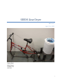

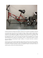
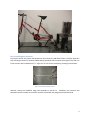


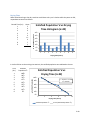
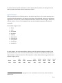

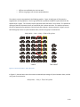
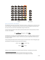


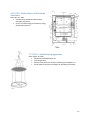


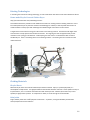
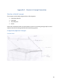

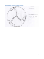
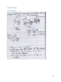

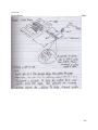

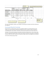

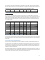

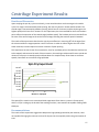

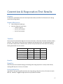
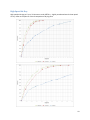

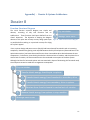

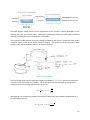
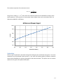

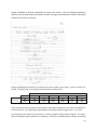
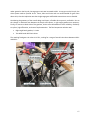
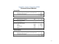
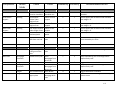


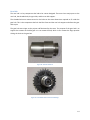
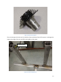
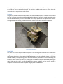
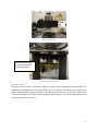
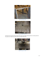
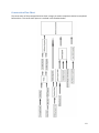

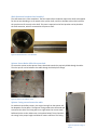
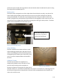
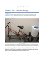
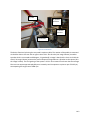

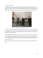


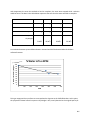
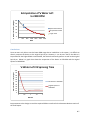


![MapInfo [v9.5 - v10.0] User manual PDF](http://vs1.manualzilla.com/store/data/005662542_1-c58f11f989f54f88b5c049879cd1b1b4-150x150.png)