1
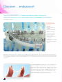
class II correction Durable • Effective FLEX DEVELOPER™ | ADENTA | SMART INNOVATION | V05a SMART INNOVATION SMART INNOVATION SMART SMART SMART INNOVATION INNOVATION INNOVATION SMART INNOVATION SMART INNOVATIO SMART INNOVATION Bringing German Engineering to Orthodontics SMART SMART INNOVATION INNOVATION SMART INNOVATION Discover… endurance! The Flex Developer™ = Durable and effective Class II Correction “Even after continuous use for many months there is no breakage or loss of power.” Dr. Winsauer, Austria Presenting the next generation for CLass II corrections Reliable Highly durable and flexible Eliminates breakage issues More comfortable / slim patient profile No loss of power Easy to install Customize your force per patient Customize your length per patient No storing of different sizes Extensive research promoted our engineers to once again ask the difficult question: ”How do we improve Class II treatment?” We have all experienced Class II treatment difficulties: appliance breakage issues, elastics - undesired side effects, bulky and uncomfortable, complicated or hard to handle appliances, loss of power and last but not least the need to stock different sizes and forces. The Flex Developer™ is designed to deliver a reliable force between mandible and maxilla. The power derives from an elastic mini rod that can be thinned to enable a range of treatment forces. The force ranges from 1,000 grams to as little as 50 grams (10 – 0,5 N) and is individually adjusted for the perfect fit for each patient. This one of a kind elastic rod is highly durable, able to withstand the rigorous forces of treatment while maintaining its power and elasticity. Bringing German Engineering to Orthodontics class ii correction 2.5 mio cycles - Unbreakable and long lasting elasticity The Flex Developer's mini rod was put through an Un test (in vitro). This test was stopped after 2,5 Mio. cycles, as practically no changes in the force deliverance rate could be observed. This equals 500 days of treatment time, if a bite Length and force adaptability rate of 5,000 cycles per day is estimated. Clinical testing proved optimal endurance and strength and has set a new benchmark for inter-maxillary force deliverance. Reducing undesired effects The ability to customize the mini rod to your patients’ needs eliminates your need to stock many different sizes and forces. Length can be customized quickly, just measure and cut. Force can be customized easily by reducing the diameter of the mini rod, producing a range of forces from 1,000 grams to as low as 50 grams. In contrast to effect of Class II mechanics with elastics’ where the forces increase and become more vertical with increased mouth opening (undesired), the Flex Developer™ only produces a horizontal force just before tooth contact. The vertical force is negligible. When the mouth is opened, it slides back passively, without force or side effect - the patient can move the mandibular from left to right freely without any locking issues. More comfortable and a slim patient profile The Flex Developer’s plastic mini rod offers the added benefits of streamlining this appliance, less material and increased ultra-smooth comfort of the appliance. Applications Distalising upper molars (HG-like) Mesialising lower molars or premolars (Aplasia or after extractions) Cl II-corrections between upper and lower dental arch Helping to grow the mandible forward Retrusion of upper incisors Protrusion of lower incisors Midline corrections (unilateral application) Unilateral dental Cl II correction (unilateral application) Space closure (even single-sided) in the mandible (aplasia) Unique features Reliable Highly durable Length adaptable to individual need Force adaptable to individual need Lasting elasticity Relockable anterior piece Measuring gauge for quick installation Can be combined with lip bumper or headgear Securing mini disc for pin safety Auxiliary bypass arch pre-bent for precise function Small and streamline – more comfortable Easy to install Flex Developer™ order info Item # Articel Description FDS-KIT FDA-KIT Sales Unit Flex Developer™ Starter Kit 5 Patients 1 kit Flex Developer™ Refill Kit 5 Patients 1 kit All Flex Developer™ individual parts can be ordered separately on request! 1 Flex Developer™ (“FD”) User Manual Ball pin - (for fixation and to vary exerted force as needed) Posterior attachment module Anterior hooklet module (relockable) Preformed bypass arch Elastic minirod (polyamide) for and length adjustable as needed System Requirements: • Upper molar bands with triple tubes, lower molar bands with double tubes of either .018” or .022” slot size • Full mouth fixed appliance • FD technology can also be used with removable appliances (acrylic plates or split) The application of controllable intermaxillary forces for: • Cl II correction (‘internal head gear’). • creating space or anchorage in the maxilla. • space closure (even single-sided) in the mandible (aplasia). In contrast to effects of Cl II mechanics with elastics where the forces increase and become more vertical with increased mouth opening (undesired), the Flex Developer only produces a horizontal force just before tooth contact. The vertical force is negligable small. When the mouth is opened, it slides back passively, without force or side effects. The elastic mini rod can be shortened to any desired length, thus reducing the cost of stocking various sizes. If preferred preadjusted FD’s are available in fixed lengths of 20/22/24/26 and 29 millimeters. As well as being adjustable in length, the elastic mini rod can also be thinned down to smaller diameters. This way, forces can be set freely between 50 and 1000 grams (0.5 - 0 10 N). Even after several months of uninterrupted treatment, the force reduction for the Flex Developer™ is less than 5%. The Flex Developer™ produces up to 1mm tooth movement per month. It is also ideal for cases of minimal patient cooperation or unilateral application as well. Plasma welding guarantees robustness as well as long lasting and inert quality without any soldering. Installation is really easy with the preformed bypass arches, a unique measuring gauge and the D=FD’s relockable anterior hooklet module. Bringing German Engineering to Orthodontics 2 Flex Developer™ Preformed Bypass Arch - Inserting and Adjusting Before installation, please bend the little hook of the lower molar attachment towards caudal and gingival. This way, the elastic mini rod is prevented from getting stuck underneath the molar attachment. With the unique measuring gauge (“Smiley - side”) measure the distance between the back-edge of the lower molar buccal tube and the back edge of the lower canine bracket. Shorten the preformed bypass arch leaving additional 5mm to the measured length (x + 5mm) Note: Right preformed bypass arches are bundled with red elastics. The bypass arches hooklet open toward the gingival side. 3 Flex Developer™ Preformed Bypass Arch - Inserting and Adjusting Insertion of preformed bypass arch, so that the arches hooklet is situated between the lower canine bracket and the lower first premolar bracket. Place two markings on the auxiliary arch. The posterior and first mark between molar tube and premolar bracket, the anterior and second below the premolar bracket. Using some fine three prong pliers, make the first bend downwards at rearmost marking (bending angle of approx. 40°). A second bend upwards will bring the preformed bypass arch back parallel to its rear upper section (bayonet bend). If necessary, take preformed bypass arch out again and curve it between two fingers, so that the anterior end is resting without tension between canine and Not correct Correct first pre-moiar. Note: Never form or hold the preformed bypass arches with rough pliers. Close the preformed bypass arches hooklet with pointed Weingart-pliers from the occlusai side. This way, a ring is formed that can slide loosely on the main full arch wire. Tip: A small drop of light curing resin on the preformed arches hooklet may take away vertical movements while it is stili able to move horizontally. Avoid contact with canine bracket! On completion, the bypass arch should run approx. 3-4mm underneath the premolar brackets. There should also be enough space between the premolar bracket and the bayonet bend of the bypass arch (important, other-wise the FD could get caught here!). According to the desired application, the preformed bypass arch is now pulled back and its end bent upward (!) behind the buccal tube, (stop bend). This way molars or entire posterior tooth segments are mesialized and hence spaces (aplasia, etc.) can be closed towards mesial. Or: It touches the canine bracket and is not bent up at the rear. Now without bending, lower canine and front teeth are protruded. (Note: in this case, the lower full arch wire should also not be bent distally!). Space will be created. 4 Flex Developer™ Elastic Mini Rod - Shortening and Adjusting After the decision whether to bend the preformed bypass arch distal or to leave it straight, we must now consider a possible distal stop-bend of the upper main arch. If it stays straight distally, the force of the elastic mini rod triggers a distalization of the corresponding upper molar (like a headgear). In this way, space is created in the upper tooth arch. If you decide to bend the upper arch wire behind the molar attachment upward (stop bend), the whole upper dental arch is distalized en bloc or used as an anchorage. In order to know the length of the minirod please measure the distance between entrance of upper headgear-tube and labial end of preformed bypass arch. (“Smiley side = measuring side”). In this 60° case 20mm. Now shift the anterior hooklet module along the mini rod towards posterior attachment module. Note: The hooklet must be inclined towards its tube with approx. 60°. The hook must never be bent severly forwards and backwards as this might lead to immediate or delayed fracture. MORE Pre-cut lengths available! INFO Bringing German Engineering to Orthodontics 5 Flex Developer™ Operating Range 38mm FD - Competitors 38mm 800 Herbst Scharnier 3.0 Flex Developer mini rod 3mm (unthinned diameter) 700 600 500 400 Force in grams 300 2.0 Flex Developer Jasper Jumper Eurecka mini rod 2mm 1.5 Flex Developer mini rod 1.5 mm 200 100 0 1 2 3 4 5 Activation in mm 6 7 8 9 10 11 12 13 14 15 Thanks to the possibility to adjust the FD’s spring force to any height between 50 and 1000 grams (Pond), a wide operating range is achieved. Thus we achieve numerous types of applications, both for removable and permanent treatment orthodontic techniques. Here you see the characteristic curves for the forces, which result from the various degrees of activation. Comparison between 4 different treatment devices with a joint length of 38mm. Operating Range 26mm FD Operating Range 32mm FD 800 800 700 700 600 3.0 Flex Developer 3.0 Flex Developer Feder nicht ausgedünnt = 3 mm 600 Feder nicht ausgedünnt = 3 mm 500 500 2.0 Flex Developer 400 Feder auf 2 mm ausgedünnt 400 2.0 Flex Developer Feder auf 2 mm ausgedünnt 200 1.5 Flex Developer 100 Feder auf 1,5 mm ausgedünnt 0 1 2 3 4 Dráha v mm 5 6 7 8 9 10 11 12 13 14 15 300 Sila v gramoch Sila v gramoch 300 200 1.5 Flex Developer 100 Feder auf 1,5 mm ausgedünnt 0 1 2 3 4 Dráha v mm 5 6 7 8 9 10 11 12 13 14 15 By shortening the installation length, the rate of force delivery is increased (at equal bending). Here it is recomended to slender the elastic mini rod in order to stay within the therapeutic force range. 6 Flex Developer™ Elastic Minirod: Shortening & Adjusting - Clamping The Anterior Hooklet Now push the FD into the tube of the measuring gauge and read the measured value (here 20mm) at the anterior rim of the posterior attachment module. Then cut off the excess minirod piece with the sharpened side cutters. 10° Shift the anterior hooklet module to the front end of the elastic mini rod and make the buccal part of the hooklet align with the buccal part of the posterior attachment module. The anterior hooklet ist leaning slightly more to the gingival side (10°)! Crimp the tube at the anterior module twice with the side cutter. Two notches become visible at the sides. Open the hooklet now, if additionally necessary, so that it can be attached to the preformed bypass arch later. 7 Flex Developer™ Smoothing Minirod & Hooklet Module - Reducing Elastic Minirod The excess elastic minirod is removed with the brown Gyroform®-grinder. The metal edges of the anterior hooklet module are rounded additionally in order to increase patient comfort. The FD can be reduced with the green Gyroform®-grinder. This should be done equally over its entire length in order to avoid buckling under stress. Figures 2.0, 1.5, 3.0 represent for standard reducing to 2.0mm (75%) and 1.5mm (50%) as well as not reduced 3.0mm (100%). Tip: General rule: the shorter an FD is, the higher the force development at activation and also vertical force direction! Hence we recommend not to use lengths below 19mm and reducing the FD in good time. Further information about forces, page 7 (diagrams) and page 26-27 (force measurement). Bringing German Engineering to Orthodontics 8 Flex Developer™ ™ Insertion Of Flex Developer The pin held by the securing disc is now (without the need of pliers) inserted into the maxilliary headgear tube from the distal side. After arriving through the tube the first Millimeter of the pin is bent back (securing but no activation). The patient should now push the lower jaw forwards taking the tension off the mini rod. Now the FD can easily be attached to the bypass arch. Shorten the preformed bypass arch leaving additional 5mm to the measured length (x + 5mm) Note: Right preformed bypass arches are bundled with red elastics. The bypass arches hooklet open toward the gingival side. By moving the lower jaw back again, the Flex Developer comes under tension for the first time. Activate by twisting the pin’s end and secure pin with alastic ring to the molar hook. Take out securing mini disc. The ball end of the pin should be bent to upward approx. 30° (important!). Pin fixation with elastic. 9 Flex Developer™ Force Adjustments for Bypass Arch - Force Measurement Elastic Minirod The hooklet is now closed with Weingart pliers. If necessary, the FD can quickly be taken out quickly for checking and reinserted for continued use. Tip: If the bypass arch and the hooklet module should be to close to the gingiva (pale spot), insert a buccal torque mesial to the molar tube using the torquing key. Never treat sliding surface of the preformed bypass arch with pliers! The force of the Flex Developer™ can be adjusted and measured individually. The FD force gauge has a short piece of wire with pointed ends soldered T-shaped to its end. The point is placed at the plastic anterior end of the FD, measuring direction towards pinball. Now, you have to push until the hooklet starts to move on the bypass arch. The force measured in this way with mouth closed, is the actual effective force of the FD. 10 Flex Developer™ Re-activation - The Patient Helping Himself There are three possibilities to re-activate the FD or to enhance its effect: First, through shortening the pin (‘roll in’) and second by shortening the preformed bypass arch towards distal. Therefore the sliding arch is pushed back and its end bent upwards (! !) distal to the molar tube. Possibly, the stepped bend may have to be located further towards mesial (arrow B). Caution: The upward stop bend of the bypass arch distal to the molar attachment can interfere with the end of the main treatment arch. Do not bend downwards, as this often interferes with the FDmini rod (arrow A). Thirdly, the sliding section of the arch can be shortened .through the application of UV-setting polymer (Heliosit®, Triade®) Note: Deposit the polymer using a probe around the pre¬formed bypass arch whilst hardening under the UV lamp. The booklet eye of the preformed bypass arch must remain free on the full arch! Bringing German Engineering to Orthodontics The patient helping himself: In the case of difficulties of any kind (ulceration, locking, claustrophobia), the patient can temporarily de-activate the FD. To do so, the booklet at the anterior module has to be opened slightly with some cutting-pliers (e.g. nail clippers). The FD can then be disconnected from the bypass arch and hooked to the upper full arch wire. Convenient for both patient and doctor! 11 Flex Developer™ Elongated Bypass Arch - HG-pin E-bypass arch (like e-longated or extraction): In the case of a short lower dental arch, it is convenient to obtain quite a long preformed bypass arch, in order to be able to insert a longer FD (better horizontal force deliverance). As an example: For the right treatment side a left bypass arch (‘not redmarked’) is bent as shown in the picture. This way an elongated right bypass arch is created, that will let the FD slide forward until under¬neath the canine bracket. The smooth curve should be formed in with fingertips. For remaining installation, see page 6-13. Remember: A former right bypass arch converts into a left E-bypass arch after remodelling. In the starter kit, there are also 2 pieces HG-pins made of .017”x.025” SS wire with ball ready-mounted. This way, the FD is attached at the auxiliary molar tube and enables the simultaneous use of headgear, lip bumper or reversed headgear. 201554 Head Office adenta Germany Sales Office adenta SPAIN Sales Office adenta USA Adenta GmbH Gutenbergstrasse 9 D–82205 Gilching Germany Adenta SPAIN c/León, 11-13, 1r. piso 08911 Badalona Barcelona - Espana Adenta USA Inc 81 Clover Road Ivyland PA 18974 U.S.A +49 8105 - 73436 - 0 +49 8105 - 73436 - 22 +(34) 933 844 705 +(34) 933 844 153 1-888-942-2070 toll free +1-215-942-2070 phone Mail: [email protected] Internet: www.adenta.de Mail: [email protected] Internet: www.adentaspain.com Mail: [email protected] Internet: www.adentausa.com 201554