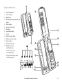
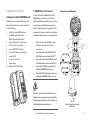
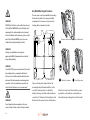
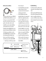
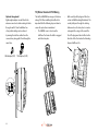
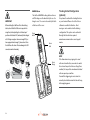
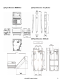
1
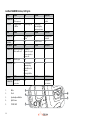
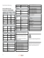
IsatDock MARINE User Manual BEAM IsatDock MARINE Installation and User Manual Product name: IsatDock MARINE Manual revision: 04 Part Number: USRMAN006205 Release date: April 2013 BEAM Communications Pty Ltd 8 Anzed Court, Mulgrave, Victoria, 3170, AUSTRALIA Information furnished by BEAM Communications Pty Ltd (BEAM) is believed to be accurate and reliable. However, no responsibility is assumed by BEAM for its use, or for any infringement of patents or other rights of third parties, which may result from its use. No license is granted by implication or otherwise under any patent or patent rights of BEAM. BEAM reserves the right to change specifications at any time without notice. Copyright © 2010 BEAM Communications Pty Ltd. All rights reserved 2 About Beam Communications Beam Communications, a wholly owned subsidiary of World Reach Limited (WRR), listed on the Australian Stock Exchange, is a world leader in design, manufacture and distribution of specialised communications equipment for the Inmarsat Satellite Network. Beam’s commitment to be at the forefront has continued to increase its share of the global satellite communications market. Its premium distribution network spans the world. Recognized as a leading provider of satellite communication solutions, Beam specializes in Voice, Data, Tracking and customized solutions. Beam develops innovative products and services to meet market demands and niche applications. Beam’s leading edge products are deployed in a wide range of vertical markets including Maritime, Transport, Government, Defence, Mining, Construction, Forestry, Emergency Services, Relief Aid, Telemetry and Rural Telephony. BEAM Communications Pty Ltd 8 Anzed Court, Mulgrave, Victoria, 3170, AUSTRALIA Web: Information: Support: Tel: Fax: www.beamcommunications.com [email protected] [email protected] +61 3 8588 4500 +61 3 9560 9055 Supported by a dedicated team of professionals, Beam has developed solid relationships with its peers and network of distributors worldwide. IsatDock MARINE - Installation & User Manual 3 Conventions in this Manual These notes will appear throughout this manual and should be taken into consideration. Warning or Caution This symbol and associated text indicate a warning note providing information to prevent damage to equipment or personal injury. Note/Important/Tip Header This symbol and associated text indicate a note providing general operating information. Interference Header All wireless phones may get interference, which could affect performance. Record Header Write details of your unit for easy reference when required. Ideal when troubleshooting. 4 Terminology TERM DESCRIPTION Falcon Falcon Configuration Tool - MS Windows Install SMS Short Message Service Mobile Originating Describes a call initiated by the IsatDock Mobile Terminating Describes an incoming call being answered by the IsatDock IsatPhone Pro The Inmarsat IsatPhone Pro handset ® The ® symbol, mark and logos are owned by the respective companies of which the symbol follows. Any use of such marks by Beam Communications is under license. Other trademarks and trade names are those of their respective owners. RF Radio Frequencies SMA Sub Miniature version A co-axial RF connection RJ11 Connector type and reference for the POTS telephone port RJ9 4P4C connector for the privacy handset POTS Plain Old Telephone Service GPS Global Positioning System GSPS Inmarsat’s Global Satellite Phone Service PABX Private Analogue Branch Exchange Package Contents Optional Accessories Additional Information Check that your IsatDock MARINE package contains all of the following items: The following optional accessories are available for your IsatDock MARNIE FF 1 x IsatDock MARINE docking station Active Antennas • ISD710 Maritime Antenna (Active) For the latest in supporting software and documentation for IsatDock please go to www.beamcommunications.com/support/ marine FF 1 x 110-240V AC Plug Pack FF 1 x Privacy Handset FF 1 x 10-32V DC Power Cable FF 1 x 2m Alert wiring loop FF 2 x Handset Locking Keys FF 1 x Wall Mounting plate FF User Manual & Quick Start Guide Falcon Configuration Tool is available for download from: http://www.beamcommunications.com/ support/marine Alert / Tracking Antenna Cable Kits for Active Antennas • ISD932 6m cable kit (Active) • ISD933 13m cable kit (Active) • ISD934 18m cable kit (Active) • ISD935 31m cable kit (Active) • ISD938 40m cable kit (Active) • ISD942 50m cable kit (Active) • ISD943 60m cable kit (Active) • ISD944 70m cable kit (Active) • ISD945 80m cable kit (Active) • ISD946 90m cable kit (Active) • ISD947 100m cable kit (Active) To configure the alert / tracking functionality on your IsatDock, you must first install the Falcon software, which also includes the Beam USB Drivers for Microsoft Windows based operating systems. Other Resources Available Online - Advanced Configuration – inbuilt to Falcon - Quick Start Guide & Manual - Antenna Installation Guide - IsatPhone Pro firmware upgrade if required Additional Accessories • RST055 UPS Battery Pack See your service provider for pricing and availability of these quality BEAM accessories. IsatDock MARINE - Installation & User Manual 5 CONTENTS BEAM IsatDock MARINE Part Number 2 About Beam Communications 3 Conventions in this Manual 4 Terminology Package Contents 5 Optional Accessories IsatDock MARINE Front Panel IsatDock MARINE Buttons/LED lights 13 Installation Guidelines 14 7 IsatDock MARINE Usage IsatDock FCC Information Docking & undocking the IsatPhone Pro handset Electronic Devices Tracking & Alert Configuration (optional) Pacemakers Operation of the IsatPhone Pro Other Medical Devices Placing Voice Calls Posted Facilities Mute Mode Aircraft USB Driver Installation Specification Summary 32 Electrical & Environmental Specifications - IsatDock MARINE (1) Physical Dimensions - MARINE Dock (2) Physical Dimensions - Privacy Handset 15 Installing the IsatDock MARINE Cradle Tracking and Alert Operations 6 Assuring Quality of Service Configuration using Remote Commands Equipment Overview Installation Procedure Other Resources Available Online IsatDock Key Lock Configuration using Falcon Guidelines for Electrical Connections Alert/Tracking Safety Transceiver IsatPhone Pro 11 Tracking/Alert Monitoring Routing Cables Additional Information Safety Information IsatDock MARINE Key Features 23 (3) Physical Dimensions - Wall Bracket Trouble Shooting 34 Beam Warranty Conditions 35 Safety Information IMPORTANT! Please read the following information carefully before installing and using the IsatDock MARINE. Failing to follow instructions may compromise the safety of the product and may result in personal injury and/or equipment damage. Please consult your supplier if you have any further questions. The IsatDock MARINE is a low power docking station for the IsatPhone Pro handset. When ON, it will charge the IsatPhone Pro handset whilst docked in the IsatDock MARINE. Refer to the appropriate section of this IsatDock MARINE Installation & User Manual for additional safety information. • Store the system in a cool and dry area. • Do not submerge the system in water. • Do not place foreign metal objects or debris in the system. If debris enters into the system, please return to the manufacturer for service. WARNING DO NOT open equipment. There are no userserviceable parts inside. If a DC power supply is to be used, its output must comply with the Safety Extra Low Voltage (SELV) requirements of IEC60950. All connectors must only be connected to equipment ports which comply with the Safety Extra Low Voltage (SELV) requirements of IEC60950. POTENTIALLY EXPLOSIVE ATMOSPHERES • Turn your phone OFF and DO NOT remove your battery or remove the IsatPhone Pro handset from the cradle when you are in any area with a potentially explosive atmosphere. • Obey all signs and instructions. • Sparks from your battery in such areas could cause an explosion or fire resulting in bodily injury or even death. IsatDock MARINE - Installation & User Manual • Areas with a potentially explosive atmosphere are often but not always clearly marked. They include, but are not limited to: »» fuelling areas such as gasoline stations »» below deck on boats; »» fuel or chemical transfer or storage facilities; »» areas where fuel odors are present (for example, if a gas/propane leak occurs in a car or home); » » areas where the air contains chemicals or particles, such as grain, dust, or metal powders; »» any other area where you normally would be advised to turn off your vehicle engine. 7 Safety Transceiver IsatPhone Pro Your handset is a low power radio transmitter and receiver. When it is ON, it receives and also sends out radio frequency (RF) signals. (NOTE: Refer to Inmarsat IsatPhone Pro Manual for additional Information) • The Inmarsat IsatPhone Pro handset has an in-built transceiver which is designed to be used with an external antenna. This antenna transmits RF energy. The BEAM antenna (fitted via an extension coaxial cable to the cradle) must be located more than > 55cm from the human body (person) when in operation. • International agencies have set standards and recommendations for the protection of public exposure to RF electromagnetic energy. These standards are based on extensive scientific review by scientists, engineers, and physicians from universities, government health agencies, and industry groups They review the available body of research to develop ANSI standard. These ANSI standards are reviewed regularly for research development. 8 »» International Commission on Non-Ionizing Radiation Protection (ICNIRP) 1996 »» Verband Deutscher Elektrotechniker (VDE) DIN-0848 »» United States Federal Commission, Radio Frequency Exposure Guidelines (1996) »» National Radiological Protection Board of the United Kingdom, GS 11, 1988 »» American National Standards Institute (ANSI) IEEE. C95. 1-1992 • Do not operate your satellite telephone when a person is within 55cm of the antenna. A person or object within 55cm meters of the antenna could impair call quality and may cause the phone to operate at a higher power level than necessary and expose that person to RF energy in excess of that established by the FCC RF Exposure Guidelines. • As a precaution, please maintain the maximum body distance possible from the antenna during call transmission. WARNING ROAD SAFETY COMES FIRST! Do not use a hand-held cellular terminal, satellite phone or mobile when driving a vehicle, unless it is securely mounted in a holder for speakerphone operation. Before making a call with a handheld terminal, satellite phone or mobile, park the vehicle stationary. Please obey local road laws for handsfree speakerphone operation. Speakerphones (hands-free) must be installed by qualified personnel. Faulty installation or operation can constitute a safety hazard. IMPORTANT Cellular & Satellite terminals or mobiles operate using radio signals and communication networks. Because of this, the connection cannot be guaranteed at all times or under all conditions. Therefore, you should never rely solely upon any wireless device for essential communications, for example emergency calls. IsatDock FCC Information This equipment has been tested and found to comply with the limits for a Class B digital devices, pursuant to Part 15 of the FCC Rules. These limits are designed to provide reasonable protection against harmful interference in a residential installation. This equipment generates, uses, and can radiate radio frequency energy and, if not installed and used in accordance with the instruction manual, may cause harmful interference to radio communications. However, there is no guarantee that interference will not occur in a particular installation. If this equipment does cause harmful interference to radio or television reception, which can be determined by turning the equipment off and on, the user is encouraged to try to correct the interference by one or more of the following measures: • Reorient or relocate the receiving antenna • Increase the separation between the equipment and receiver • Connect the equipment into an outlet on a circuit different from that to which the receiver is connected. • Consult the dealer or an experienced radio/TV technician for help. This device has been designed to operate with antennas ISD710 AT1595-82, ISD715/ISD720 AT1595-83 and having a maximum gain of 6dB i dB. Antennas having a gain grater than 6dBi dB are strictly prohibited for use with this device. To reduce potential radio interference to other users, the antenna type and its gain should be so chosen that the equivalent isotropically radiated power (EIRP) is not more than that required for successful communication WARNING Changes or modifications not expressly approved by BEAM Communications could void the product warranty. IsatDock MARINE - Installation & User Manual 9 Electronic Devices Other Medical Devices Most modern electronic equipment is shielded from RF signals. However, certain equipment may not be shielded against the RF signals from your wireless phone. If you use any other personal medical device, consult the manufacturer of your device to determine if it is adequately shielded from external RF energy. Your physician may be able to assist you in obtaining this information. Turn your phone OFF in health care facilities when any regulations posted in these areas instruct you to do so. Hospitals or health care facilities may be using equipment that could be sensitive to external RF energy. Pacemakers The Health Industry Manufacturers Association recommends that a minimum separation of six inches (6”) be maintained between a wireless phone’s antenna and a pacemaker to avoid potential interference with the pacemaker. These recommendations are consistent with the independent research by and recommendations of Wireless Technology Research. Persons with pacemakers: • Should ALWAYS keep the phone more than six inches from their pacemaker when phone is turned ON. • Should turn the phone OFF immediately if you have any reason to suspect interference is taking place. 10 Posted Facilities Turn your phone OFF in any facility where posted notices require such as hospitals and on-board aircraft. Aircraft Airline regulations prohibit using your phone while in the air. Consult the local Aviation Authority for guidelines on use of the equipment on board an aircraft. IsatDock MARINE Key Features IsatDock MARINE is an intelligent docking station specifically designed for the Inmarsat IsatPhone Pro satellite handset. IsatDock MARINE allows the IsatPhone Pro handset to be used in a wide variety of applications. It enables you to use an intelligent RJ11/POTS connection with a standard corded, cordless or DECT handset. Alternatively, it can also be interfaced with a PABX system. IsatDock MARINE has an in-built speakerphone for convienent handsfree operation. Equipped with internal GPS, the IsatDock MARINE provides an intelligent tracking and alert reporting system that can be easily configured to support periodic polling or emergency alert reporting. POTS/RJ11 • Supports standard cordless & corded telephones (5 REN) • The POTS phone can be run 600m (2000 ft from unit) • Easily integrated to PABX system • Ring, busy & dial tones • Superior voice quality Tracking & GPS • • • • • In-built GPS engine Tracking & alert monitoring capable Periodic position reports or remotely polled Triggered position status message Compatible with other tracking applications Installation • Supports 10 - 32V DC power input • Flexible installation via wall or desk mounting option • Supplied with 110 - 240V AC/DC Plug pack Quality • • • • Professional industrial design 2 year replacement guarantee 100% factory tested Full certified, Inmarsat Type Approved, FCC, RoHS, CE, IEC60945, AS/EN60950 Panic & Alerts IsatDock Design • • • • • • • • Securely holds IsatPhone Pro handset Robust design and construction Key lockable & secure mount to wall/desk IP54 Rated enclosure Charges IsatPhone Pro handset ready for use Integrated antenna connection Integrated USB connectivity Cable routing LHS/TOP/BOTTOM • Panic Alert button in-built to cradle • Option of additional wired alert buttons In-Built Speakerphone • In-built speaker and microphone IsatDock MARINE - Installation & User Manual 11 Tracking / Alert Monitoring IsatDock MARINE has an in-built GPS module that can provide tracking, monitoring and alert management in various land and sea based applications within various types of vehicles, vessels or fixed site locations. The GPS module provides accurate positioning and enables tracking worldwide. The tracking function has to be configured and enabled on the IsatDock MARINE via Falcon. Once turned ON, tracking and alert messages can be sent to a phone number, e-mail address, or any tracking application via SMS/email. Tracking messages can be sent from the IsatDock MARINE in the following ways; Periodic position reporting, which is preset during configuration of the IsatDock MARINE. A current location position can be sent at any time by pressing the Track button on the front of the IsatDock MARINE The Alert mode can be activated on the IsatDock MARINE in the following ways; Use the two button press (know as the Alert button) on the front of the cradle. Use an external alert button/emergency push button connected to the alert loop 12 Once activated, alert messages will be sent to the preset destination continuously until the alert is disabled either remotely or locally on the IsatDock MARINE unit. Configuration using Falcon Falcon can be downloaded from: http://www.beamcommunications.com/ support/marine Follow the instructions in the downloaded application to install. Once complete, connect your PC to the USB port of the terminal and start Falcon. You can then use the application for a range of options such as: • View the status of the terminal (signal, temperature, input voltage) • Firmware maintenance • Configure different POTS/RJ11 settings NOTE Entering the firmware upgrade mode will be accompanied by a long beep followed by three short beeps. Configuration Using Remote Commands Configuration instructions or “Remote Commands” can be sent to the terminal via SMS, and most settings are supported that are normally accessible from Falcon. Please refer to the Falcon user manual for more information. NOTE Due to memory limitations it is recommended that users have no more than 20 SMS messages in their inbox. If this amount is exceeded the processing of remote commands and the ability to retrieve the messages via the Falcon tool may be compromised. 1 Equipment Overview 1. 2. 3. 4. 5. 6. 7. 8. 9. 10. 11. 12. 13. 14. IsatDock MARINE unit Cover Lock Clasp Marine Cover Mounting Cup (spring or springless cup option) Privacy Handset Speaker (under handset) Microphone Speakerphone Button Key lock IsatPhone Pro Eject Button IsatPhone Pro (not included) Function Buttons STATUS Indication LED Back Panel Connectors a. USB Data Interface b. Alert Loop connection c. RJ11/POTS interface d. DC power and accessory input e. RJ9 Privacy handset 3 9 10 2 4 14 11 5 a b c d e 6 12 7 13 8 IsatDock MARINE - Installation & User Manual 13 Installation Guidelines This guide outlines the process for installing the IsatDock MARINE in conjunction with an Inmarsat IsatPhone Pro handset and antenna. This kit must not be used with any other device other than the Inmarsat IsatPhone Pro handset and other compatible accessories. • Only trained personnel should install communication equipment. • Ensure that the unit is protected from dirt and moisture. • Select an area to mount components where there is no interference with other objects. • A strong mounting surface should be chosen to ensure the terminal doesn’t loosen over time. • Mount all components securely for safe day to day operation. Always use the supplied mounting hardware. • Leave space around the unit to allow airflow and ensure there is adequate clearance for cables. • Ensure the units can be easily accessible for servicing. 14 Routing Cables • Route cables so they are protected from pinching, sharp edges, and crushing. • Use grommets wherever a cable must pass through a hole in a metal panel • Keep all in-line connectors accessible. • For an extra clean installation, a hole may be driven through the surface directly behind the docking station. • electrical noise that interferes with the electrical radio system operation. The ignition system is the most common source of electrical noise interference. Before you begin installation, ensure that the ignition wiring and connections to the battery are in good working condition. Install provided fuses into the +BATT and ignition sense (accessory) wires. Guidelines for Electrical Connections The system is designed to operate 10 to 32 Volt DC electrical systems only • The best power connection point for the positive primary power lead is the positive terminal of the battery. Often, direct connection to the battery is inconvenient, and you may find it easier to connect the positive leads to the starter solenoid. Always select a point as close as possible to the battery. • Connect the negative primary power leads to a good ground point on the vessel or at the battery. If you must attach the negative primary power lead directly to the negative pole of the battery. • Many parts of a vessel can produce WARNING Do not connect the IsatDock power cable to power the unit until the full installation is completed. Installation Procedure Installing the IsatDock MARINE Cradle Install the components in the following order. More detailed instructions can be found in the sections following. 1. Install the external BEAM antenna 2. (A) Wall Mounting Orientation (B) Desk Mounting Orientation 3. Connect the privacy handset & cup 4. Access to rear connector bay 5. Connect POTS/RJ11 Interface 6. Connect the Alarm Loop (optional) 7. Connect USB 8. Connect power cable 9. Cable routing 10. Water Resistant IP54 Rating 1) BEAM Antenna Connection Anntena Connection Diagram To connect the IsatDock MARINE to the GSPS BEAM Antenna, requires the use of certified satellite and GPS antenna cables to be used. These cables are purpose built cables as approved by Beam to manage the power requirements for the antenna system. Approved cables can be found at www.beamcommunications.com/support/marine. SMA 1. 2. 3. 4. 5. Refer to the antennas installation guide for antenna mounting and location requirements. Connect the antenna cable labelled “GPS” to the SMA antenna connector labelled “GPS”. Connect the antenna cable labelled “Inmarsat” to the SMA antenna connector labelled “ISAT”. Connect the GPS-SMA (Female) cable end to the IsatDock MARINE’s SMA connector. Connect the TNC (Female) antenna cable end to the IsatDock MARINE’s satellite connector. NOTE Refer to the section “Antenna Installation” for more information on antenna placement and installation. Only Beam approved antenna cables should be used with all docking stations and antennas. IsatDock MARINE - Installation & User Manual GPS Antenna Cable SMA 2 3 4 5 SMA Satellite Antenna Cable TNC ISD710 Marine Active Antenna with Pole Bracket 15 2a) Wall Mounting Orientation WARNING DO NOT pull with force on the cables from the rear of the IsatDock MARINE. Please install strain relief clamping for the antenna cables where required. Correct installation of the antenna system is a vital part of the IsatDock MARINE system, to ensure reliable functionality, and drop-free calls. There are nine screw holes available for mounting the bracket to a wall. It is recommended that a minimum of 2 screws are used to ensure the docking station is mounted securely. a Fit the docks feet in the large holes of the bracket WARNING Changes or modifications not expressly approved by BEAM Communications could void the product warranty. WARNING To satisfy FCC RF exposure requirements for mobile transmitting devices, a separation distance of 55cm or more should be maintained between the antenna of this device and persons during device operation. To ensure compliance, operations at closer than this distance is not recommended. WARNING: Do not place the antenna anywhere there is a source of heat or fumes such as the ship’s exhaust. 16 b There are four keyhole shaped slots in the mounting bracket that mate with feet on the rear of the docking station. To attach the bracket, the larger end of the keyhole will pass over the feet. The bracket is then slid up to lock the feet into the narrow section of the keyhole. Slide the dock down c Final lock position Once the dock as been locked onto the mounting bracket on the wall, two security bolts are then slid into place locking the dock to the wall. Security Bolts Two security bolts ensure the MARINE docking unit is firmly fixed to the wall and only removed by an ‘authorized’ (the security key holder) personnel. Once the IsatDock MARINE is fitted to the wall, these two security bolts prevent the docking station from sliding back up freeing the dock. The security bolts are 4mm in diameter and have a slot for a flat blade screwdriver. The bolt under the privacy handset mounting cup must be fitted prior to the cup being screwed into place. The second bolt is placed under the IsatPhone Pro in the recess for the handset antenna cover. Both bolts are then covered with plugs. As the second bolt is under the IsatPhone Pro, access to the bolt is denied when the handset is locked into the cradle. 2b) Desk Mounting Orientation 3) Privacy Handset & Mounting Cup The IsatDock MARINE supports a desk mount configuration. Depending on the users requirements the docking station supports both a flat and raised orientation on the desk. The Privacy Handset is conveniently mounted on to the IsatDock MARINE enclosure, providing a local handset function. The Privacy Handset connects to the docking station via a RJ9 connector. The privacy handset is connected beneath the rear panel of the IsatDock. Once connected, the cable is run out through the foam and placed in the ‘S’ channel through the base of the phone. To configure the IsatDock for a desk installation: 1. Fit the mounting bracket to the back of the IsatDock as shown in section (2a) wall mounting directions. 2. Flip the feet out if required and locate the IsatDock on the desk. RJ9 connection When desk mounting, the security bolts are not required to be fitted. Changing Cups 1. Unhook the privacy handset from cup. 2. Remove cup cover to expose screws. 3. Unscrew 3 screws with a phillips screwdriver. 4. Detach the cup and replace with the spring or springless cup. IsatDock MARINE - Installation & User Manual 17 1 2 (1) Springless Cup for Normal light-use Desk mounted cradle position. The ‘springless’ cup is fitted to the docking station with the mounting clip in a ‘flush’ position. 3 4 Wall mounted cradle position. The mounting clip can be slid out and reversed, producing a protruding point that the Privacy handset rests upon. For a wall mounted docking station this retains the privacy handset and the ‘springless’ cup has enough height to allow the handset to rise up off the clip and out of the mounting cup There are two unique mounting cups for the privacy handset. (1) springless cup for either a desk mounted cradle position or a wall mounted cradle position. (2) spring cup for heavy duty use. 18 (2) Spring Cup - Heavy duty use cup In harsh environments, the Privacy handset is actively retained in the mounting cup. This is achieved by using the ‘spring’ mounting cup. To remove the handset from the cup, the phone is lifted up against the pressure of the spring until it clears the lower mounting pip and can be removed from the docking station. 4) Access to Rear Connector Bay 5) Connect RJ11/POTS Interface For the IsatDock MARINE, the external cable interfaces are at the rear of the docking station. The cover panel creates the IP rating for the electrical interface and retains the cables in their respective channels. The cover panel is fixed in place by seven screws. Any standard analogue POTS (= Plain Old Telephone Service) Telephone is supported by the IsatDock MARINE. It supplies power to the analogue phone as well as ring, dial and busy tones. The analogue phone can be connected by up to 600m of cabling to the IsatDock MARINE. RJ11 port a a. b. c. d. e. b c d e USB Data Interface Alert loop connection RJ11/POTS interface DC power and accessory input RJ9 Privacy handset IsatDock MARINE - Installation & User Manual 19 6) Connect Alert Loop (optional) 7) USB Port Connection 8) Connecting Power to the Dock IsatDock MARINE provides a standard BEAM alert loop. This provides a normally CLOSED wire loop, which can be used to connect to any passive type of button, relay, or reed switch in which the action breaks the loop (OPEN) to activate the alert state. Connect the alarm cable directly to the alert loop connection. The cable can be extended to long runs up to 45 meters. This alert loop can support multiple alert buttons / switches wired in SERIES, whereby any one of these will OPEN (activate) the loop when pressed. This provides the same functionality as pressing the mute and track button simultaneously on the dock and manually placing the unit into alert/emergency mode. IsatDock MARINE has a micro USB Data Port to enable upgrading of the firmware, advanced configuration, and data connection. The Dock can be powered from the supplied AC Plug pack, or connect to an external 10-32V DC power supply. USB Data Port ISD950 AC Plug Pack Installation 20 For installation using ISD950 110-240 AC plug pack, connect the 4-way Microfit connector from the plug pack to the 4-way power connector on the rear of the IsatDock MARINE. In this configuration the ignition/accessory status is always ON. DC Power Source Installation 2. YELLOW RED BLACK The DC power cable has three wires, RED, BLACK and YELLOW. The RED and BLACK wires are used for the power connection while the YELLOW wire can be connected to a vessels accessories, ignition or other similar circuits to control the ON/OFF status of the IsatDock MARINE in synchronization with a vessels operation. By default, the IsatDock MARINE will stay on for 20 minutes after this input (YELLOW wire) is switched off. If a call is in progress while this occurs, the IsatDock MARINE will stay on for 20 minutes after the call is terminated. Please follow the steps below to connect the DC power cable to the vehicle battery power and the IsatDock MARINE. 1. Route the wire end of the DC power cable to 3. 4. 5. the connection point. Connect the BLACK wire to the negative terminal of the battery (10A fuse recommended) or the vehicle chassis (if negatively grounded chassis). Connect the RED wire to the positive terminal of the battery. It is recommended to add the 5A fuse (supplied) between them. Connect the YELLOW wire to the vessel accessory power. If the accessory power is unavailable, this may be connected to a switch. It is recommended to add a 1A fuse between them. The accessory wire enables the IsatDock MARINE to turn on and off as the vessel key is enabled or disabled. If this function is not required, the YELLOW wire MUST be connected to the RED wire. Connect the 4-way Microfit connector on the DC power cable to the 4-way power connector on the rear cable loom of the IsatDock MARINE. RED (+) Vin 10 to 32VDC BLACK (-) OV Power Ground YELLOW ON/SLEEP 9) Cable Routing The IsatDock provides three different cable routing options when installing the docking station. Cables may exit via path ‘A’ that travels around to the top of the dock allowing for the interface cables to be run with the external antenna connections. Path ‘B’ directs cables out the base of the dock while path ‘C’ results in cables exiting to the side. A To Battery Positive Terminal (Requires 5A Fuse) C To Negative Terminal or chassis To ON/OFF switch (1A Fuse recommended) B IsatDock MARINE - Installation & User Manual 21 10) Water Resistant IP54 Rating Optional through-wall Right angled adaptors can be fitted to the antenna connectors to allow routing of cables through a wall. A “clean” installation free of any visible cabling can be achieved by running the interface cables from the connector bay along path ‘A’ and through the same holes. SMA Adaptor (GPS) 22 TNC Adaptor (GSPS) The IsatDock MARINE has an ingress Protection rating of 54. When installing the IsatDock it is important that the following steps are taken to ensure the protection is maintained. • The MARINE cover is closed over the IsatPhone Pro. Ensure the latch is engaged and clicked in place. • Both security bolts & plugs are fitted (see section 2a Wall Mounting Orientation). The security bolts pass through the docking station and need to be in place to create a seal against the o-rings at the rear of the Dock. The plugs must also be fitted on the front side of the Dock under the Mounting Cup and IsatPhone Pro. IsatDock MARINE Usage • Rear Cover Screwed in Place. The rear cover of the MARINE dock must be screwed down with at least the four screws indicated below to ensure the waterproof seal is achieved (indicated by a & b). Care should be taken placing the cables in the respective cable guides as any damage to the sealing foam will compromise the water resistant foam seal. a 3. Docking & undocking the IsatPhone Pro handset To place the IsatPhone Pro into the docking unit, both the ‘covers’ on the external antenna connectors and the USB/Audio connectors need to be opened. 1. The antenna ‘cover’ must be placed at 90 degrees to the antenna connector cavity and run parallel to the top edge of the phone. 2. The ‘cover’ in the base of the phone should be in the a 90 degree opened position. To dock the handset, align the IsatPhone Pro with the phone tray and slide the handset down until it seats flush to the bottom of the tray. Swing the phone down into the cradle by applying pressure to the top of the handset. An audible ‘click’ is heard when the phone is in the docked position. 1 1 A 2 b To remove the handset from the cradle, press the EJECT button at the top of the docking station. The dock will swing out and the handset can be removed. Eject Button C IsatDock MARINE - Installation & User Manual B 23 IMPORTANT: Before docking the IsatPhone Pro to the docking station, check that the USB cover is open, able to swing free (without putting it in a “locked open” position as illustrated in ‘A’) and ready for docking at a 90-95 degree angle as shown on image ‘B’. If you have a gap similar to image ‘C’, please do not force the IsatPhone Pro down. This can damage the USB connector and void warranty. A B C 90° 95° 180° IsatPh one PR IsatDOCK 24 O Cover Latch Cover Seal 0° MARINE Cover The IsatDock MARINE docking station achieves an IP54 rating over the handset by the use of a hinged cover . The cover is released by the latch at the base of the cover. Cover Hinge Tracking & Alert Configuration (optional) It is optional to activate the tracking function on your terminal. Please refer to the Falcon software to enable this function. Alert messages can be enabled via the tracking configuration. This option can be activated through the below link as required. www.beamcommunications.com/support/ marine NOTE If the Beam alarm loop is going to be used with an external button, remember to enable this external loop in the Falcon settings. Once enabled, the loop will be armed and activated with an open-loop condition. To avoid false triggering, be sure to have the normally closed button wired into the alert loop, before applying power. Operation of the IsatPhone Pro Placing Voice Calls Prepare the Inmarsat IsatPhone Pro Ensure that the IsatPhone Pro Handset has the latest compatible firmware installed. For more information visit: www.beamcommunications.com/support/ marine Bluetooth® calls via IsatPhone Pro The IsatDock MARINE allows for Bluetooth audio calls to be placed via the IsatPhone Pro handset while docked. Consult the IsatPhone Pro manual for further information on pairing and Bluetooth discovery setup. Starting Up 1. Retract the antenna on the IsatPhone Pro handset. 2. Place the IsatPhone Pro as per instructions “Docking & Undocking” on page 23-24. 3. Turn vehicle ignition on. The IsatPhone Pro will automatically power up/on and the handset will then start to initialise a 3 tone rising beep indicate when a successful connection has been made between the docking station and the IsatPhone Pro. 4. Wait for the IsatPhone Pro handset to register on the Inmarsat network. The STATUS LED on the docking station will turn green when a successful registration has taken place. 5. You are now ready to make and receive calls. NOTE: (1) If the IsatPhone Pro is removed from the dock during a call, the call will drop out during this transition (2) One common cause for connection failure is a flat IsatPhone Pro battery which prevents the IsatPhone Pro from turning ON. In these instances the docking station will attempt to charge the Isatphone Pro handset while it is switched OFF, until enough charge is present for the IsatPhone Pro to turn ON. This charging period can take up to 20 minutes depending on how flat the battery. IsatPhone Pro handset The IsatDock MARINE provides charging power to the IsatPhone Pro handset. The IsatPhone Pro battery is a lithium-ion cell which has a safety temperature range whilst charging of 0 to 45 degrees Celsius (32 to 113 degrees Fahrenheit). Due to the increased heating effects on the IsatPhone Pro handset whilst it is docked and being charged, it is ideal for the ambient temperature to be at least 18 degrees below the 45oC upper limit for the handset to charge the battery whilst docked. If the battery temperature exceeds this limit, then the IsatPhone Pro may cease charging until the temperature is reduced. IsatDock MARINE - Installation & User Manual Speakerphone Phone Call Use Mobile Originating 1. By default the Oceana 800 will start all calls in speakerphone mode when dialing on the keypad if RJ11 and privacy handset remain on hook. 2. Dial using the full Inmarsat dialing sequence eg. 00 country code and telephone number on the IsatPhone Pro handset keypad whilst docked. Press the GREEN key on the IsatPhone Pro to start the connection. 3. A message will display on the IsatPhone Pro handset to indicate the call is progressing. 4. Once the call is connected, the STATUS LED will flash to indicate a call is in progress. 5. To terminate the call, press the RED key on the IsatPhone Pro handset or press the speakerphone button. 25 Options: A. During a call, you may use the optional privacy handset by taking the privacy handset out of its cup. This automatically directs the call audio to the privacy handset. B. To return the call back to “speakerphone” mode, press the speakerphone button and return the privacy handset to its cup. Mobile Terminating 1. Answer the incoming call by pressing the speakerphone button or the GREEN key on the IsatPhone Pro handset. 2. Once the call is in progress, the same options are available as described in “Speakerphone Phone Call – Mobile Originating” 3. Press the RED key on the IsatPhone Pro handset or press the speakerphone button to terminate the call. RJ11/POTS phone use Mobile Originating 1. Lift the RJ11/POTS phone handset “OFFHOOK” and listen for the dial tone. The mute LED will flash yellow to indicate the RJ11/POTS is in use. 2. Dial using the full Inmarsat dialing sequence eg. 00 country code and telephone number on the RJ11 telephone keypad. 26 3. 4. 5. A message will display on the IsatPhone Pro handset indicating the number called and that the call is progressing. Once the call is connected, the STATUS LED will flash to indicate a call is in progress. Place the RJ11/POTS phone handset “ON HOOK” to terminate the call. Mobile Terminating 1. The RJ11/POTS phone will sound its ringer. 2. Lift the RJ11/POTS phone handset “OFFHOOK” to answer the call. NOTE (default operation) For mobile terminated calls, the call will remain active for ~90 seconds even if the RJ11/POTS phone is placed ON HOOK. To end the call immediately, the other calling party must hang up (ON HOOK) the call. Data use Ensure that you have installed the BEAM USB driver – see section “USB Driver Installation” (shown on page 27). The Oceana 800 terminal allows for circuit switched data via the BEAM USB data port that is presented when plugged into your PC. Follow the normal procedures with your data application to connect. Once connected, the Call LED will be flashing YELLOW. Once the circuit switched connection has ended, the Call LED will turn off. NOTE: During a data connection, the RJ11/POTS handset cannot make or receive voice calls. An unavailable tone will be heard on the RJ11/POTS handset. Privacy Handset Use Mobile Originating 1. Remove the privacy handset from its cup 2. Dial using the full Inmarsat dialing sequence eg. 00 country code and telephone number on the IsatPhone Pro keypad whilst docked. Press the GREEN button to start the connection. 3. A message is displayed on the IsatPhone Pro to indicate a call is in progress. 4. Once the call is connected, the STATUS LED will flash to indicate a call is in progress. 5. Press the RED key on the IsatPhone Pro handset or return the privacy handset to its cup to terminate the call. Options: A. During a call, you may switch to “speakerphone” mode by pressing the speakerphone button on the IsatDock. Return the privacy handset to its cup. B. To return the call back to the privacy handset, remove the privacy handset from its cup. Mobile Terminating 1. Answer the incoming call by un-cupping the privacy handset from its cup. 2. Press the RED key on the IsatPhone Pro handset or return the privacy handset to its cup to terminate the call. Mute Mode Tracking and Alert Operations Mute functionality The mute function of the IsatDock MARINE allows the user to mute the uplink microphone audio on the privacy handset and/or internal hands-free microphone. 1. During a call, Press the Mute button on the front of the IsatDock MARINE, a RED LED will illuminate the Mute button to confirm that the uplink audio is muted. 2. To exit the mute mode, press the mute button once. Enable Tracking & Alert The Tracking & Alert function is NOT enabled by default and it has to be configured and enabled using the Falcon software via the micro-USB connection to the IsatDock MARINE. Various configuration options are available to the user in Falcon. The message delivery method is also set using Falcon. Please refer to the Falcon User Guide for more details on how to configure and enable the Tracking & Alert function on the IsatPhone Pro. USB Driver Installation Send Tracking Position In order to send a tracking message, the following conditions must be fulfilled. 1. The GPS receiver has acquired enough satellite signals and navigational data to calculate a positional solution (fix). 2. The IsatPhone Pro handset is registered with the GSPS network. 3. Tracking is configured and enabled via Falcon. The Track LED will stay off if the Tracking function is disabled. It will turn solid GREEN if all of the above conditions are satisfied. Otherwise, it will flash in GREEN if the Tracking function is enabled but no GPS fix and/or GSPS registration has occurred. The IsatDock MARINE USB data port requires an interface driver to be installed on the user’s computer prior to undertaking data communication. This driver supports the following operating systems: Windows XP (SP3 or above), Vista & 7 You can download the Windows Driver for the IsatDock from http://www.beamcommunications.com/ support/marine IsatDock MARINE - Installation & User Manual 27 To manually send a tracking message of the current location A. Apply a single press to the Track button. A single beep will sound (if configured in the Falcon). Activate Alert Mode Alert mode can be activated by one of the following two methods: 1. Press and hold both the Track and Mute buttons together for 2 seconds. A single beep will sound (if configured in the Falcon). 2. If enabled by the Falcon, press and hold the external panic button (optionally wired into the Alert Loop wires). Once triggered into the Alert mode, the Track LED turns RED. The message then attempts to be sent. The Track LED will flash in RED when the alert message is sent. (Rate: 1.5sec off, 1.5sec on, etc). The Track LED will flash in YELLOW when the alert message is acknowledged by a remote host. (Rate: 1sec off, 4sec on, etc) Clearing an Alert To clear the alert mode press and hold the Track button for seven seconds. A single beep will sound, and the LED will show re-armed state (GREEN). 28 IsatDock Key lock A barrel type lock is situated in the top of the dock. When locked, the eject button cannot be depressed and the IsatPhone Pro cannot be removed from the dock. Once locked, the access to the security bolt beneath the handset is also denied thus ensuring the MARINE docking station cannot be removed from the mounting bracket. Locked Open IsatDock MARINE Front Panel Location Button Mode Action LED/Sound Mute Press on/off In a Call: LED turns RED - Muted Mute the microphone (uplink) on the privacy handset if connected to cradle. LED turns OFF - Not muted Up/Down In a Call: Audio will sound louder/quieter in privacy handset with each press. LED flashing Yellow - RJ11/POTS in use Increase/decrease volume on the internal hardware or privacy handset (optional accessory) if connected to cradle. OR Out of Call: A beep will sound indicating the increased/decreased ring tone volume Increase/decrease volume of incoming ring tone on the internal hardware speaker. + Single Press (1 second) In Alert Mode*: Single Press (7 seconds) In Alert/Emergency Mode*: Two button press (2 seconds) In Tracking Mode*: A beep will sound indicating alert/emergency mode is activated# Activate the Alert/Emergency mode. LED changes from GREEN to solid RED. A beep will sound to indicate that a tracking message is to be sent# Send a tracking message to the pre-configured destination LED changes from RED/YELLOW (solid or flashing) to GREEN# Clear the alert/emergency mode and return to the Tracking mode*. LED changes to flashing RED once the alert has been sent. LED will change to slow flashing YELLOW once the remote server has acknowledged receiving the alert. + Brightness dual button simultaneous press (1 second) Out of Call: Enter LED brightness change mode. Press UP and DOWN arrows to vary intensity. Mode will automatically exit after 5 seconds after the last button press. Speakerphone press ON/OFF In a Call: Terminate call if speakerphone mode is active Activate speakerphone mode if Privacy Handset mode is active. Out of Call: Answer inbound call in speakerphone mode All LED’s will change to WHITE and a single beep will sound when entering brightness change mode. A short double beep will sound when exiting change mode. LED turns GREEN - Speakerphone mode active LED turns OFF - Speakerphone mode not active * This action is optional, only when the Tracking Mode for your IsatDock MARINE is configured and activated. A beep will only sound if audible alerts are enabled in the Falcon # IsatDock MARINE - Installation & User Manual 29 IsatDock MARINE Buttons/LED lights TRACK GREEN RED ILLUMINATED Tracking enabled, GPS fix acquired. Alert mode activated N/A YELLOW Tracking and alert disabled FLASHING Tracking enabled No GPS fix Alert message sent N/A Alert message acknowledged by remote party/server WHITE/OFF MUTE GREEN RED YELLOW WHITE/OFF ILLUMINATED N/A Outgoing audio is muted N/A Outgoing audio is not muted FLASHING N/A N/A POTS/RJ11 in use N/A LED STATUS GREEN RED YELLOW WHITE/OFF ILLUMINATED Handset registed and able to make a call Handset not registered/no signal and canort make or receive calls N/A N/A FLASHING Call in Progress N/A N/A N/A ALTERNATING N/A Error detected in communicating with IsatPhone Pro handset. N/A N/A SPEAKER GREEN RED YELLOW WHITE/OFF ILLUMINATED Speakerphone mode active N/A N/A Speakerphone mode inactive Flashing Red/Blue 1. 2. 3. 4. 5. 30 Mute Track Speakerphone Button Up & Down STATUS LED 1 2 4 5 3 Assuring Quality of Service There are conditions that can compromise the quality of the service you may receive. These include: • Obstructions • Cabling • RF Interference Obstructions Nearby tall buildings or similar structures, heavily leafed trees and mountains can all degrade performance as they block the signal between the antenna and the satellites. Inmarsat performance is immune from natural environments such as clouds, fog, rain, snow, wind and smoke. Cabling Using an externally mounted antenna provides an ideal solution for many applications. It is very important that both the antenna cabling and antenna are BEAM approved products. Always ensure all RF connectors are screwed together firmly and ensure there are no sharp bends in the cabling between the IsatDock MARINE and the antenna. RF interference All wireless devices, including satellite telephones, are susceptible to RF (radio frequency) interference from other electronic devices. This problem is more evident when numerous antennas and broadcasting devices are located within close proximity to each other. Mitigation of RF Interference Service degradation due to RF interference can be significantly improved by: • Increasing the distance and moving the antenna off axis from the source of the interference, and • Using an external band pass filter and an external antenna. WARNING Failure to use BEAM approved antenna cables will result in degraded performance and may damage the IsatDock MARINE. This will void the product warranty. Symptoms of RF interference Symptoms of RF interference often resemble those that arise when an antenna is being operated with an obstructed view of the sky. Some of these symptoms include; erratic or no signal strength indication dropped calls or warbled or otherwise distorted voice. These symptoms may be intermittent or persistent, depending largely on the interference source, its distance, strength and frequency relative to the antenna. IsatDock MARINE - Installation & User Manual 31 Specification Summary Operational Limits Altitude 18000m, Velocity 515m/s ISD942 - 50m SMA/TNC Cable Kit (Active) Dynamics 4G ISD943 - 60m SMA/TNC Cable Kit (Active) Electrical & Environmental Specifications - IsatDock MARINE Average Power Consumption Current @ 12v Average Power w/o IsatPhone Pro 130mA Standby + Charging 360mA 4.3W Transmit + Charging 875mA 10.5W Sleep Mode 5mA 60mW Peak Current 3.5A 42W Watts 1.6W Alert Button in-built Two button press ISD945 - 80m SMA/TNC Cable Kit (Active) 1 x alarm loop Bare wire - “Normally closed” loop IN to OUT ISD946 - 90m SMA/TNC Cable Kit (Active) Track In-built - single key press RST410 - “Alert Pendant” Kit Connectors / Interfaces RST055 - UPS Battery Pack RJ11/2-wire, 5REN @ 600m, Adjustable dial, ring, busy tone configured frequency and adaptive impedance. Kit Contents BEAM Antenna TNC-Female 110-240V AC Plug Pack GPS Antenna SMA-Female Privacy Handset 10-32V DC 4-way microFit (AC/DC adaptor, or DC lead) 10-32V DC Power Cable Privacy Handset Port RJ9 connector Handset locking key Configuration /Data USB Micro User manual & Quick Start Guide In-built speaker/microphone Wall mounting plate 270 x 189 x 101 (mm) 10.6 x 7.4 x 4 (inches) Weight - dock 1.67kg 3.67lbs Speakerphone Total Kit Weight 2.72kg 5.99lbs Certifications Operating Range -30oC to +70oC -22 F to +158 IP54 Rating Storage -35oC to +85oC -31oF to +185oF 0oC to +45oC +32oF to 113oF 5 = Protected against dust limited ingress (no harmful deposits) Humidity o o <= 75% RH GPS Module (internal) 4 = Protection against water sprayed from all directions limited ingress permitted. 2m Alert wiring loop NOTE: Specifications are subject to change without notice. Accessories ISD710 - Maritime Antenna (Active) * It is ideal for the ambient temperature to be ISD932 - 6m SMA/TNC Cable Kit (Active) approximately 18 degrees below the 45oC upper limit for ISD933 - 13m SMA/TNC Cable Kit (Active) the handset to charge the battery whilst docked. Channels 14 tracking, 51 channel acquiring Update Rate 1Hz Accuracy Position 2.5m CEP, Velocity 0.1m/s, Timing 300ns Acquisition TTFF Cold 29sec, Hot 1sec ISD935 - 30m SMA/TNC Cable Kit (Active) Sensitivity -161 dBm ISD938 - 40m SMA/TNC Cable Kit (Active) 32 IsatDock MARINE Inmarsat Type Approval, FCC, CE Compliance, Electrical Safety, RoHS, Industry Canada, C-Tick, EMC Compliance Environmental Specifications Battery Charging Temp* ISD947 - 100m SMA/TNC Cable Kit (Active) POTS/RJ11 Physical Specifications Dimensions ISD944 - 70m SMA/TNC Cable Kit (Active) I/O Alarm/Alert ISD934 - 18m SMA/TNC Cable Kit (Active) (1) Physical Dimensions - MARINE Dock (2) Physical Dimensions - Privacy Handset 27.13mm 206.97mm 49.70mm 100.8mm 268.9mm 42.28mm 188.2mm (3) Physical Dimensions - Wall Bracket 47.16mm 60.0mm 80.5mm 80.5mm 53.0mm 53.0mm 175.71mm 500.88mm 23.16mm 51.0mm Ø 5.2mm 243.96mm 69.0mm IsatDock MARINE - Installation & User Manual 69.0mm 33 Trouble Shooting This chapter provides information to help you troubleshoot problems you may encounter while running the IsatDock. Q1 How do I know if my IsatPhone Pro is registered on the Inmarsat network? Q4 A The STATUS LED of the docking station will change to GREEN when the handset is registered and able to make calls on the network. The IsatPhone Pro will also indicate “Inmarsat” in the top left corner of the screen display. A Q2 The handset and docking station turn’s OFF every 20minutes? A Ensure the Ignition/Accessories wire is connected to power. If this is not connected, or connected to ground the docking station will go into sleep mode after 20 minutes by default. Q5 Q3 No power on IsatDock. A A Check power is connected to the interface unit. Ensure the Connector cable to the IsatDock is firmly fitted. Check all the connection cables to and from the IsatDock. Visit: http://www.beamcommunications. com/support Q6 Dropped calls A Due to a satellite network when you are in motion the satellite signal may become obstructed (such as buildings, bridges, tunnels, larger vehicles). Check the antenna connection. Ensure the antenna cable has not been damaged. Ensure that only approved antenna cable has been used. Refer to Antenna Install Guide on Beam website support. 34 The signal bars are low or fluctuating and call quality is poor. Ensure all antenna connectors are tight. The antenna is operating in a location that it can see the satellite and there are no obstructions. Beam certified antenna cabling is being used and there are no sharp bends or cuts in the cable. If using a fixed passive antenna, ensure it is orientated correctly and pointing at the satellite. I am looking for the latest manuals and support information on the docking station ? Q7 B party has “no audio” A Privacy Handset must be docked in its cup when not in use. Check that MUTE is not ON (indicated by turning RED) Check the signal strength on the handset. Ensure the Headset connector at the base of the IsatPhone Pro is not obstructed and there is no dust or foreign objects in the connector socket. Q8 The docking station appears to be cycling ON/OFF and the handset is not registering. A Ensure the power supply can provide at least 3.5A at 12volts. If power is being supplied from a battery, ensure the connections are tight and the contacts are clean. Beam Warranty Conditions 2. BEAM Communications does not warrant any 7. BEAM Communications will not accept BEAM Communications gives this express warranty (along installation, maintenance or service of the Products responsibility for any invoiced goods or services with extended warranty endorsements, where applicable) not performed by BEAM, nor does it warrant the use that are not covered by a BEAM Communications in lieu of all other warranties, express or implied, including of Products with unapproved ancillary products. written purchase order. Under no circumstances BEAM Communications will correct any defects does BEAM Communications agree to pay for fitness for a particular purpose. This constitutes our sole in material or workmanship of products labour or other related expenses associated with warranty and obligation with regard to our products as manufactured by BEAM which appear within (12) the troubleshooting and/or repair of our product well as the Customer’s sole remedy. months and (24) months replacement warranty BEAM Communications expressly disclaims all for Docking Station units ONLY, from the date liability and responsibility for any special, indirect or of shipment by BEAM Communications to the on product specifications that are current at the consequential damages or any further loss of any kind Customer. time of publication. Product specifications, designs whatsoever resulting from the use of our product(s). BEAM Communications will repair or replace, at and descriptive literature are subject to change The Customer’s sole and exclusive remedy and the our option, any defective product,provided that as improvements are introduced. Although we limit of BEAM liability for any loss whatsoever, shall our analysis and/or inspection discloses that such announce changes as they occur, we cannot not exceed the purchase price paid by the Customer defects developed under normal and proper use. guarantee notification to every Customer. BEAM This warranty does not extend to goods subjected Communications warrants delivered product to All products manufactured by BEAM Communications to liquid or particulate ingress, extreme humidity, conform to the most current specifications, designs are warranted to be free from defects in material and misuse, neglect, accident or improper installation, workmanship in accordance with and subject to the or to maintenance or repair of products that have following terms and conditions: been altered or repaired by anyone except BEAM for particular categories of products or Customers, 1. Communications unless otherwise stated in writing. by information sheets published as deemed The warranty is a return-to-base warranty and appropriate by BEAM Communications. The freight is paid by the sender. warranty for third party Products is that of the A charge of USD $150 including return freight will third party and not BEAM warranty. (without limitation), warranties of merchantability and for the product to which a claim is made. 3. 4. This warranty is limited to the original Customer only. It cannot be transferred or assigned to third 5. parties unless the intent to transfer to a third party is expressly indicated in a purchase order and/ 6. or warranty-processing arrangements have been be made for testing returned product which is not agreed upon in writing by BEAM. defective or is found to be defective as the result without prior specific written authorization. 8. Information in our descriptive literature is based and descriptive literature. 9. This warranty policy may be expanded or limited, of improper use, maintenance or neglect. IsatDock MARINE - Installation & User Manual 35 BEAM Communications GLOBAL HEAD OFFICE Tel: +61 3 8588 4500 Fax: +61 3 9560 9055 AMERICAS Tel: +1 954 976 5062 EUROPE Tel: +44 208 144 1405 Fax: +44 208 289 3542 www.beamcommunications.com PART #: USRMAN006205 Info: [email protected] Support: [email protected]