1
Pololu Simple Motor Controller User’s Guide
© 2001–2015 Pololu Corporation
Pololu Simple Motor Controller
User’s Guide
View document on multiple pages. [https://www.pololu.com/docs/0J44]
View this document as a printable PDF: simple_motor_controllers.pdf
[https://www.pololu.com/docs/pdf/0J44/
simple_motor_controllers.pdf]
https://www.pololu.com/docs/0J44/all
Page 1 of 108
Pololu Simple Motor Controller User’s Guide
1. Overview . . . . . . . . . . . . . . . . . . . . . . . . . . . .
1.1. 18v7 Included Hardware . . . . . . . . . . . . . . . .
1.2. 18v15 and 24v12 Included Hardware . . . . . . . . .
1.3. 18v25 and 24v23 Included Hardware . . . . . . . . .
1.4. Supported Operating Systems . . . . . . . . . . . . .
2. Contacting Pololu . . . . . . . . . . . . . . . . . . . . . . .
3. Getting Started . . . . . . . . . . . . . . . . . . . . . . . . .
3.1. Installing Windows Drivers and Software . . . . . . .
3.2. Installing Linux Drivers and Software . . . . . . . . .
3.3. Understanding the Control Center Status Tab . . . . .
3.4. Errors . . . . . . . . . . . . . . . . . . . . . . . . . .
3.5. LED Feedback . . . . . . . . . . . . . . . . . . . . .
4. Connecting Your Motor Controller . . . . . . . . . . . . . .
4.1. Connecting Power and a Motor . . . . . . . . . . . .
4.2. Connecting a Serial Device . . . . . . . . . . . . . . .
4.3. Connecting an RC Receiver . . . . . . . . . . . . . .
4.4. Connecting a Potentiometer or Analog Joystick . . . .
5. Configuring Your Motor Controller . . . . . . . . . . . . . .
5.1. Input Settings . . . . . . . . . . . . . . . . . . . . . .
5.1.1. Configuring a Limit or Kill Switch . . . . . .
5.2. Motor Settings . . . . . . . . . . . . . . . . . . . . .
5.3. Advanced Settings . . . . . . . . . . . . . . . . . . .
5.4. Upgrading Firmware . . . . . . . . . . . . . . . . . .
6. Using the Serial Interface . . . . . . . . . . . . . . . . . . .
6.1. Serial Settings . . . . . . . . . . . . . . . . . . . . .
6.2. Binary Commands . . . . . . . . . . . . . . . . . . .
6.2.1. Binary Command Reference . . . . . . . . .
6.3. ASCII Commands . . . . . . . . . . . . . . . . . . .
6.3.1. ASCII Command Reference . . . . . . . . .
6.4. Controller Variables . . . . . . . . . . . . . . . . . .
6.5. Cyclic Redundancy Check (CRC) Error Detection . .
6.6. Daisy Chaining . . . . . . . . . . . . . . . . . . . . .
6.7. Sample Code . . . . . . . . . . . . . . . . . . . . . .
6.7.1. Arduino Examples . . . . . . . . . . . . . .
6.7.2. Orangutan Examples . . . . . . . . . . . . .
6.7.3. Cross-platform C Example . . . . . . . . . .
6.7.4. Windows C Example . . . . . . . . . . . . .
6.7.5. Bash Script Example . . . . . . . . . . . . .
6.7.6. CRC Computation in C . . . . . . . . . . . .
7. Writing PC Software to Control the Simple Motor Controller
© 2001–2015 Pololu Corporation
.
.
.
.
.
.
.
.
.
.
.
.
.
.
.
.
.
.
.
.
.
.
.
.
.
.
.
.
.
.
.
.
.
.
.
.
.
.
.
.
.
.
.
.
.
.
.
.
.
.
.
.
.
.
.
.
.
.
.
.
.
.
.
.
.
.
.
.
.
.
.
.
.
.
.
.
.
.
.
.
.
.
.
.
.
.
.
.
.
.
.
.
.
.
.
.
.
.
.
.
.
.
.
.
.
.
.
.
.
.
.
.
.
.
.
.
.
.
.
.
.
.
.
.
.
.
.
.
.
.
.
.
.
.
.
.
.
.
.
.
.
.
.
.
.
.
.
.
.
.
.
.
.
.
.
.
.
.
.
.
.
.
.
.
.
.
.
.
.
.
.
.
.
.
.
.
.
.
.
.
.
.
.
.
.
.
.
.
.
.
.
.
.
.
.
.
.
.
.
.
.
.
.
.
.
.
.
.
.
.
.
.
.
.
.
.
.
.
.
.
.
.
.
.
.
.
.
.
.
.
.
.
.
.
.
.
.
.
.
.
.
.
.
.
.
.
.
.
.
.
.
.
.
.
.
.
.
.
.
.
.
.
.
.
.
.
.
.
.
.
.
.
.
.
.
.
.
.
.
.
.
.
.
.
.
.
.
.
.
.
.
.
.
.
.
.
.
.
.
.
.
.
.
.
.
.
.
.
.
.
.
.
.
.
.
.
.
.
.
.
.
.
.
.
.
.
.
.
.
.
.
.
.
.
.
.
.
.
.
.
.
.
.
.
.
.
.
.
.
.
.
.
.
.
.
.
.
.
.
.
.
.
.
.
.
.
.
.
.
.
.
.
.
.
.
.
.
.
.
.
.
.
.
.
.
.
.
.
.
.
.
.
.
.
.
.
.
.
.
.
.
.
.
.
.
.
.
.
.
.
.
.
.
.
.
.
.
.
.
.
.
.
.
.
.
.
.
.
.
.
.
.
.
.
.
.
.
.
.
.
.
.
.
.
.
.
.
.
.
.
.
.
.
.
.
.
.
.
.
.
.
.
.
.
.
.
.
.
.
.
.
.
.
.
.
.
.
.
.
.
.
.
.
.
.
.
.
.
.
.
.
.
.
.
.
.
.
.
.
.
.
.
.
.
.
.
.
.
.
.
.
.
.
.
.
.
.
.
.
.
.
.
.
.
.
.
.
.
.
.
.
.
.
.
.
.
.
.
.
.
.
.
.
.
.
.
.
.
.
.
.
.
.
.
.
.
.
.
.
.
.
.
.
.
.
.
.
.
.
.
.
.
.
.
.
.
.
.
.
.
.
.
.
.
.
.
.
.
.
.
.
.
.
.
.
.
.
.
.
.
.
.
.
.
.
.
.
.
.
.
.
.
.
.
.
.
.
.
.
.
.
.
.
.
.
.
.
.
.
.
.
.
.
.
.
.
.
.
.
.
.
.
.
.
.
.
.
.
.
.
.
.
.
.
.
.
.
.
.
.
.
.
.
.
.
.
.
.
.
.
.
.
.
.
.
.
.
.
.
.
.
.
.
.
.
.
.
.
.
.
.
.
.
.
.
.
.
.
.
.
.
.
.
.
.
.
.
.
.
.
.
.
.
.
.
.
.
.
.
.
.
.
.
.
.
.
.
.
.
.
.
.
.
.
.
.
.
.
.
.
.
.
.
.
.
.
.
.
.
.
.
.
.
.
.
.
.
.
.
.
.
.
.
.
.
.
.
.
.
.
.
.
.
.
.
.
.
.
.
.
.
.
.
.
.
.
.
.
.
.
.
.
.
.
.
.
.
.
.
.
.
.
.
.
.
.
.
.
.
.
.
.
.
.
.
.
.
.
.
.
.
.
.
.
.
.
.
.
.
.
.
.
.
.
.
.
.
.
.
.
.
.
.
.
.
.
.
.
.
.
.
.
.
.
.
.
.
.
.
.
.
.
.
.
.
.
.
.
.
.
.
.
.
.
.
.
.
.
.
.
.
.
.
.
.
.
.
.
.
.
.
.
.
.
.
.
.
.
.
.
.
.
.
.
.
.
.
.
.
.
.
.
.
.
.
.
.
.
.
.
.
.
.
.
.
3
6
7
8
9
10
11
11
16
16
20
22
25
27
34
38
42
47
47
51
52
55
58
60
62
64
67
76
80
83
90
92
94
94
98
102
105
105
106
108
Page 2 of 108
Pololu Simple Motor Controller User’s Guide
© 2001–2015 Pololu Corporation
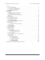
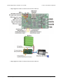
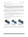
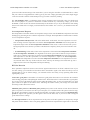
1. Overview
The Pololu Simple Motor Controllers are versatile, general-purpose
motor controllers for brushed, DC motors. A wide operating range of
up to 5.5–40V and the ability to deliver up to several hundred Watts in a
small form factor make these controllers suitable for many motor
control applications. With a variety of supported interfaces—USB for
direct connection to a computer, TTL serial for use with embedded
systems, RC hobby servo pulses for use as an RC-controlled electronic
speed control (ESC), and analog voltages for use with a potentiometer
or analog joystick—and a wide array of configurable settings, these
motor controllers make it easy to add basic control of brushed DC
motors to a variety of projects. Although this motor controller has
many more features than competing products, a free configuration
Simple Motor Controllers.
utility (for Windows 8, 7, Vista, Windows XP, and Linux) simplifies
initial setup of the device and allows for in-system testing and monitoring of the controller via USB.
For 24 V applications, we recommend the 24v12 or 24v23 versions. We strongly recommend against
using the 18v7, 18v15, or 18v25 with 24 V batteries, which can significantly exceed 24 V when fully
charged and are dangerously close to the maximum voltage limits of these lower-voltage controllers.
Using a 24 V battery with an 18vX Simple Motor Controller makes the device much more susceptible
to damage from power supply noise or LC voltage spikes.
Key Features
• Simple bidirectional control
of one DC brush motor.
• 5.5 V to 30 V (18v7, 18v15,
and 18v25) or 40 V (24v12
and 24v23) operating supply
range.
• 7 A to 25 A maximum
continuous current output
without a heat sink, depending
on controller model
• Four communication or
control options:
1. USB interface for direct
connection to a PC.
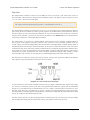
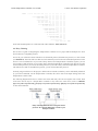
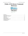
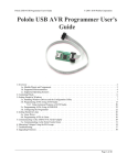
Simple High-Power Motor Controller 18v25 or 24v23 simplified
2. Logic-level (TTL) serial
connection diagram.
interface
for
direct
connection
to
microcontrollers or other embedded controllers.
3. Hobby radio control (RC) pulse width interface for direct connection to an RC receiver or RC
servo controller [https://www.pololu.com/category/12/rc-servo-controllers].
4. 0–3.3 V analog voltage interface for direct connection to potentiometers and analog joysticks.
1. Overview
Page 3 of 108
Pololu Simple Motor Controller User’s Guide
© 2001–2015 Pololu Corporation
• Simple configuration and calibration over USB with free configuration program (Windows 8, 7, Vista,
Windows XP, and Linux compatible).
Note: A USB A to mini-B cable [https://www.pololu.com/product/130] (not included) is required to
connect this controller to a computer.
Additional Features
• Adjustable maximum acceleration and deceleration to limit electrical and mechanical stress on the
system.
• Adjustable starting speed, maximum speed, and amount of braking when speed is zero.
• Optional safety controls to avoid unexpectedly powering the motor.
• Input calibration (learning) and adjustable scaling degree for analog and RC signals.
• Under-voltage shutoff with hysteresis for use with batteries vulnerable to over-discharging (e.g. LiPo
cells).
• Adjustable over-temperature threshold and response.
• Adjustable PWM frequency from 1 kHz to 22 kHz (maximum frequency is ultrasonic, eliminating
switching-induced audible motor shaft vibration).
• Error LED linked to a digital ERR output, and connecting the error outputs of multiple controllers
together optionally causes all connected controllers to shut down when any one of them experiences an
error.
• Field-upgradeable firmware.
• USB/Serial features:
◦ Controllable from a computer with native USB, via serial commands sent to the device’s virtual
serial (COM) port, or via TTL serial through the device’s RX/TX pins.
◦ Example code in C#, Visual Basic .NET, and Visual C++ is available in the Pololu USB Software
Development Kit [https://www.pololu.com/docs/0J41]
◦ Optional CRC error detection to eliminate communication errors caused by noise or software faults.
◦ Optional command timeout (shut off motors if communication ceases).
◦ Supports automatic baud rate detection from 1200 bps to 500 kbps, or can be configured to run at a
fixed baud rate.
1. Overview
Page 4 of 108
Pololu Simple Motor Controller User’s Guide
© 2001–2015 Pololu Corporation
◦ Supports standard compact and Pololu protocols as well as the Scott Edwards Mini SSC protocol
and an ASCII protocol for simple serial control from a terminal program.
◦ Optional serial response delay for communicating with half-duplex controllers such as the Basic
Stamp.
◦ Controllers can be easily chained together and to other Pololu serial motor and servo controllers to
control hundreds of motors using a single serial line.
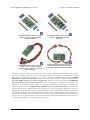
• RC features:
◦ 1/4 µs pulse measurement resolution.
◦ Works with RC pulse frequencies from 10 to 333 Hz.
◦ Configurable parameters for determining what
constitutes an acceptable RC signal.
◦ Two RC channels allow for single-stick (mixed)
motor control, making it easy to use two simple motor
controllers in tandem on an RC-controlled differentialdrive robot.
◦ RC channels can be used in any mode as limit or kill
switches (e.g. use an RC receiver to trigger a kill switch
on your autonomous robot).
◦ Battery elimination circuit (BEC) jumper can power
the RC receiver with 5 V or 3.3 V.
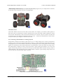
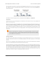
Two Pololu Simple Motor Controllers
enable mixed RC-control of Dagu Wild
Thumper 4WD all-terrain chassis.
• Analog features:
◦ 0.8 mV (12-bit) measurement resolution.
◦ Works with 0 to 3.3 V inputs.
◦ Optional potentiometer/joystick disconnect detection.
◦ Two analog channels allow for single-stick (mixed) motor control, making it easy to use two simple
motor controllers in tandem on a joystick-controlled differential-drive robot.
◦ Analog channels can be used in any mode as limit or kill switches.
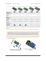
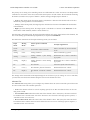
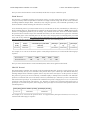
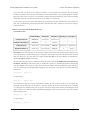
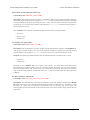
Simple Motor Controller Comparison Table
The Simple Motor Controllers are available in several input voltage ranges and output current ranges:
1. Overview
Page 5 of 108
Pololu Simple Motor Controller User’s Guide
© 2001–2015 Pololu Corporation
18v7
18v15
24v12
18v25
24v23
Absolute max
voltage:
30 V
30 V
40 V
30 V
40 V
Recommended
max
(1)
voltage :
24 V
24 V
34 V
24 V
34 V
7A
15 A
12 A
25 A
23 A
1.1" (2.8 cm)
1.1" (2.8 cm)
1.1" (2.8 cm)
1.2" (3.1 cm)
1.2" (3.1 cm)
2.1" (5.3 cm)
2.1" (5.3 cm)
2.1" (5.3 cm)
2.3" (5.8 cm)
2.3" (5.8 cm)
7g
7g
7g
12 g
12 g
Yes
Yes
Yes
No
No
Max
continuous
current w/o
heat sink:
Width:
Length:
Weight
(2)
:
Available with
connectors
installed?
1
We do not recommend using the 18v7, 18v15, or 18v25 versions with 24 V batteries, which can significantly
exceed 24 V when fully charged. The 24v12 and 24v23 are the much more appropriate controller for 24 V
applications.
2
This is the weight of the board without header pins, terminal blocks, or through-hole power capacitor.
Warning: Take proper safety precautions when using high-power electronics. Make sure you know
what you are doing when using high voltages or currents! During normal operation, this product can
get hot enough to burn you. Take care when handling this product or other components connected to
it.
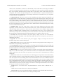
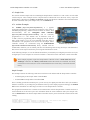
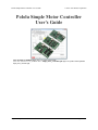
1.1. 18v7 Included Hardware
Simple Motor Controller 18v7, partial
kit with included hardware.
1. Overview
Simple Motor Controller 18v7, fully
assembled.
Page 6 of 108
Pololu Simple Motor Controller User’s Guide
© 2001–2015 Pololu Corporation
The lowest-power controller version (18v7) is available with the power capacitor and connectors included but
not soldered in (as shown in the left picture above) or with the power capacitor and connectors pre-installed (as
shown in the right picture above).
The power capacitor has a significant effect on performance; the included capacitor is the minimum size
recommended, and bigger ones can be added if there is space. A bigger capacitor might be required if the power
supply is poor or far (more than about a foot) from the controller.
Simple Motor Controller 18v7 bottom view with dimensions.
1.2. 18v15 and 24v12 Included Hardware
Simple High-Power Motor
Controller 18v15 or 24v12,
partial kit with included
hardware.
Simple High-Power Motor
Controller 18v15 or 24v12,
fully assembled.
Simple High-Power Motor
Controller 18v15 or 24v12,
partial kit with custom
power and motor
connectors (NOT included).
The medium-power controller versions (18v15 and 24v12) are available with the power capacitor and connectors
included but not soldered in (as shown in the left picture above) or with the power capacitor and connectors preinstalled (as shown in the middle picture above).
The terminal blocks are only rated for 15 A. For higher-current applications we recommend soldering thick
wires directly to the connector-free version of the board and using higher-current connectors
1. Overview
Page 7 of 108
Pololu Simple Motor Controller User’s Guide
© 2001–2015 Pololu Corporation
(as shown in the right picture above). Another benefit of the connector-free
version is flexibility in placement of the power capacitor (e.g. on the other side of the board) to accommodate
compact installations or to make room for a heat sink.
[https://www.pololu.com/product/925]
The power capacitor has a significant effect on performance; the included capacitor is the minimum size
recommended, and bigger ones can be added if there is space. A bigger capacitor might be required if the power
supply is poor or far (more than about a foot) from the controller.
Simple High-Power Motor Controller 18v15 or 24v12 bottom view with
dimensions.
1.3. 18v25 and 24v23 Included Hardware
Simple High-Power Motor
Controller 18v25 or 24v23
with included hardware.
Simple High-Power Motor
Controller 18v25 or 24v23
with included hardware
installed.
Simple High-Power Motor
Controller 18v25 or 24v23
with custom power and
motor connectors (NOT
included).
The highest-power controller versions (18v25 and 24v23) are sold without the power capacitor and connectors
installed (no fully assembled version is available). They ship with a 40×1 straight 0.1" male header strip
[https://www.pololu.com/product/965], a 5mm-pitch, 4-pin terminal block [https://www.pololu.com/product/2440], and a
power capacitor as shown in the left picture above. For applications under 15 A, these pieces can be soldered
to the board as shown in the middle picture above; higher current applications should use thick wires soldered
directly to the board or higher-current connectors [https://www.pololu.com/product/925], such as those shown in the
right picture above.
1. Overview
Page 8 of 108
Pololu Simple Motor Controller User’s Guide
© 2001–2015 Pololu Corporation
Simple High-Power Motor Controller 18v25 or 24v23 bottom view with
dimensions.
1.4. Supported Operating Systems
The Simple Motor Controller USB drivers and configuration software work under Microsoft Windows XP,
Windows Vista, Windows 7, Windows 8, and Linux.
On ARM-based Linux machines such as the Raspberry Pi, the graphical configuration program (the Simple
Motor Control Center) does not work. This is caused by problems with Mono’s implementations of WinForms
on those systems.
We do not provide any software for Mac OS X, but the controller’s USB virtual COM port is compatible with
Mac OS X 10.7 (Lion) and later. As a result, the Simple Motor Controller can be controlled from a Mac, but a
Windows or Linux computer is required if you need to change any of the configuration parameters.
Mac OS X compatibility: we have confirmed that the Simple Motor Controller works on Mac
OS X 10.7 and we can assist with advanced technical issues, but most of our tech support staff
does not use Macs, so basic support for Mac OS X is limited.
1. Overview
Page 9 of 108
Pololu Simple Motor Controller User’s Guide
© 2001–2015 Pololu Corporation
2. Contacting Pololu
You can check the Pololu Simple Motor Controller pages
[https://www.pololu.com/category/94/pololu-simple-motor-controllers]
for
additional information. The “Resources” tab on each product page
contains links to this users guide as well as other valuable resources,
such as drivers and the Simple Motor Control Center software.
We would be delighted to hear from you about any of your projects and
about your experience with the Simple Motor Controller. You can
contact us [https://www.pololu.com/contact] directly or post on our forum
[http://forum.pololu.com/]. Tell us what we did well, what we could
improve, what you would like to see in the future, or anything else you
would like to say!
2. Contacting Pololu
Page 10 of 108
Pololu Simple Motor Controller User’s Guide
© 2001–2015 Pololu Corporation
3. Getting Started
3.1. Installing Windows Drivers and Software
If you are using Windows XP, you will need to have Service Pack 3 [http://www.microsoft.com/downloads/
details.aspx?FamilyId=68C48DAD-BC34-40BE-8D85-6BB4F56F5110] installed before installing the drivers for
the Simple Motor Controller. See below for details.
Before you connect a Simple Motor Controller to a computer running Microsoft Windows, you should install the
drivers:
1. Download the Simple Motor Controller Windows Drivers and Software [https://www.pololu.com/file/
download/smc-windows-121204.zip?file_id=0J408] (5MB zip)
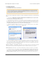
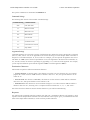
2. Open the ZIP archive and run setup.exe. The installer will guide you through the steps required to install
the Simple Motor Control Center, the Simple Motor Controller command-line utility (SmcCmd), and the
Simple Motor Controller drivers on your computer. If the installer fails, you may have to extract all the files
to a temporary directory, right click setup.exe, and select “Run as administrator”.
3. During the installation, Windows will ask you if you want to install the drivers. Click “Install”
(Windows 7, 8, and Vista) or “Continue Anyway” (Windows XP).
4. After the installation is finished, your start menu should have a shortcut to the Simple Motor Control
Center (in the Pololu folder). This is a Windows application that allows you to configure, control, and
get real-time feedback from the Simple Motor Controller. There will also be a command-line utility called
SmcCmd which you can run at a Command Prompt.
Windows 8, Windows 7, and Windows Vista users: Your computer should now automatically install the
necessary drivers when you connect a Simple Motor Controller. No further action from you is required.
Windows XP users: Follow steps 5–9 for each new Simple Motor Controller you connect to your computer.
5. Connect the device to your computer’s USB port. The Simple Motor Controller shows up as two
devices in one so your XP computer will detect both of those new devices and display the “Found New
Hardware Wizard” two times. Each time the “Found New Hardware Wizard” pops up, follow steps 6-9.
3. Getting Started
Page 11 of 108
Pololu Simple Motor Controller User’s Guide
© 2001–2015 Pololu Corporation
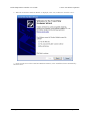
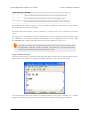
6. When the “Found New Hardware Wizard” is displayed, select “No, not this time” and click “Next”.
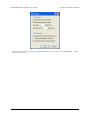
7. On the second screen of the “Found New Hardware Wizard”, select “Install the software automatically”
and click “Next”.
3. Getting Started
Page 12 of 108
Pololu Simple Motor Controller User’s Guide
© 2001–2015 Pololu Corporation
8. Windows XP will warn you again that the driver has not been tested by Microsoft and recommend that
you stop the installation. Click “Continue Anyway”.
9. When you have finished the “Found New Hardware Wizard”, click “Finish”. After that, another wizard
will pop up. You will see a total of two wizards when plugging in a Simple Motor Controller. Follow steps
6–9 for each wizard.
3. Getting Started
Page 13 of 108
Pololu Simple Motor Controller User’s Guide
© 2001–2015 Pololu Corporation
If you use Windows XP and experience problems installing or using the serial port drivers, the
cause of your problems might be a bug in older versions of Microsoft’s usb-to-serial driver
usbser.sys. Versions of this driver prior to version 5.1.2600.2930 will not work with the Simple
Motor Controller. You can check what version of this driver you have by looking in the “Details”
tab of the “Properties” window for usbser.sys in C:\Windows\System32\drivers. To get the fixed
version of the driver, you will need to install Service Pack 3 [http://www.microsoft.com/downloads/
details.aspx?FamilyId=68C48DAD-BC34-40BE-8D85-6BB4F56F5110]. If you do not want Service Pack 3,
you can try installing Hotfix KB918365 instead, but some users have had problems with the
hotfix that were resolved by upgrading to Service Pack 3. The Simple Motor Control Center and
SmcCmd will work even if the serial port drivers are not installed properly.
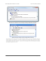
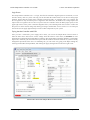
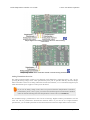
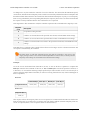
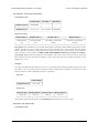
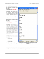
After installing the drivers, if you go to your computer’s Device Manager and expand the “Ports (COM & LPT)”
list, you should see the Command Port for the Simple Motor Controller. In parentheses, you will see the name of
the port (e.g. “COM5” or “COM6”). If you expand the “Pololu USB Devices” list you should see another entry
for the Simple Motor Controller.
3. Getting Started
Page 14 of 108
Pololu Simple Motor Controller User’s Guide
© 2001–2015 Pololu Corporation
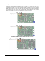
Windows Vista or Windows 7 device manager showing a Simple Motor Controller.
Windows XP device manager showing a Simple Motor Controller.
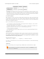
Some software will not allow connection to higher COM port numbers. If you need to change the COM port
number assigned to your USB device, you can do so using the Device Manager. Bring up the properties dialog
for the COM port and click the “Advanced…” button in the “Port Settings” tab. From this dialog you can change
the COM port assigned to your device.
3. Getting Started
Page 15 of 108
Pololu Simple Motor Controller User’s Guide
© 2001–2015 Pololu Corporation
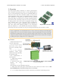
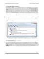
3.2. Installing Linux Drivers and Software
You can download the Pololu Simple Motor Control
Center (SmcCenter) and the command-line utility
(SmcCmd) for Linux here: Simple Motor
Controller
Linux
Software
[https://www.pololu.com/file/download/smclinux-101119.tar.gz?file_id=0J411]
(115k gz).
Unzip the tar/gzip archive by running “tar -xzvf”
followed by the name of the file. After following the
instructions in README.txt, you can run the
programs by executing SmcCenter and SmcCmd.
The Simple Motor Controller’s virtual serial port
can be used in Linux without any special driver
installation. The virtual serial port is managed by the
cdc-acm kernel module, whose source code you can
find in your kernel’s source code drivers/usb/
The Pololu Simple Motor Control Center running
class/cdc-acm.c. When you connect the Simple
under Linux.
Motor Controller to the PC, the virtual serial port
should appear as a device with a name like /dev/
ttyACM0 (the number depends on how many other ACM devices you have plugged in). You can use any terminal
program (such as kermit) to send commands and receive responses on those ports.
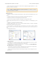
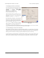
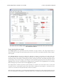
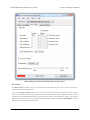
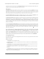
3.3. Understanding the Control Center Status Tab
After installing the software and drivers for the Simple Motor Controller, it is a good idea to run the Pololu
Simple Motor Control Center and look at the Status tab. The Status tab lets you monitor the status of your motor
controller in real time and control the speed of the motor. The Status tab also shows what errors and limits are
affecting your motor controller so it can help you quickly troubleshoot any issues you are having.
To use the Status tab, you should connect your Simple Motor Controller to your PC using a USB cable (not
included) and run the Pololu Simple Motor Control Center. This is what the Status tab should look like initially,
before you have modified any settings or connected anything to the Simple Motor Controller (besides USB):
3. Getting Started
Page 16 of 108
Pololu Simple Motor Controller User’s Guide
© 2001–2015 Pololu Corporation
The Status tab in the Simple Motor Control Center should look like this when you first connect
the controller to the PC.
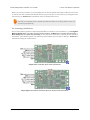
Target Speed and Current Speed
The Target Speed is the speed that the motor controller is trying to achieve. The Target Speed source is
determined by the settings in the Input Settings tab, and can come from serial/USB commands, analog voltages,
or RC signals.
The Current Speed is the speed at which the controller is currently your driving your motor. There are
several reasons why the Current Speed might be different from the Target Speed: errors, acceleration limits,
deceleration limits, brake duration, maximum speed limits, starting speed limits, and gradual temperature-based
speed limiting. If any of these things are affecting the Current Speed, the appropriate part of the Status tab will be
highlighted to let you know. Anything that is stopping the motor completely will be highlighted in red. Anything
that is limiting the speed of the motor will be highlighted in yellow.
The Simple Motor Controller represents speeds internally as a number from -3200 (full reverse) to 3200 (full
forward). However, by default the speeds in the Status Tab are displayed as percentages so -3200 (full reverse)
is shown as -100.00% and 3200 (full forward) is shown as 100.00%.
Below the Target Speed label is a two-dimensional diagram that represents the values of the inputs that are used
to set the Target Speed. This diagram is especially useful in RC or Analog mode with Mixing enabled because
3. Getting Started
Page 17 of 108
Pololu Simple Motor Controller User’s Guide
© 2001–2015 Pololu Corporation
it graphically shows you the value of both input channels and makes it easier to tell how well the Simple Motor
Controller is calibrated for your controller is.
Motor Limits
The Motor Limits box in the Status tab shows the current limits on the movement of the motor. These limits
will be equal to the hard motor limits specified in the Motor Settings tab, unless you have temporarily changed
the motor limits using the command-line utility (SmcCmd) or a serial command. For more information on these
limits, see the section that documents the Motor Settings tab.
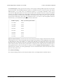
Input Channels
The Input Channels box in the Status tab shows the current status of the RC or Analog input channels of the
device.
The Raw Value is the raw, unscaled value of the input channel. For RC channels, the Raw Value is the width
of pulses received on the input line (RC1 or RC2). It is typically between 1000 μs and 2000 μs, and it is stored
internally as an integer in units of quarter-microseconds (6000 corresponds to 1500 μs). For Analog channels,
the Raw Value is the average voltage measured on the input line (A1 or A2). It is always between 0 mV and
3300 mV, and it is stored internally as a 12-bit integer (0 corresponds to 0 mV while 4095 corresponds to
3300 mV).
The Scaled Value is a number between -3200 and 3200 that is determined entirely by the Raw Value and the
scaling parameters in the Input Settings tab. If the scaling parameters are set up correctly, then the Scaled Value
should be 0 when the input is in its neutral position (if it has a neutral position), and they should be ±100 %
(±3200 internally) when the input is moved to either extreme.
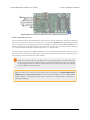
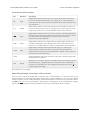
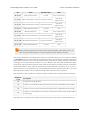
The Status column summarizes the state of each channel. Here are the different things you might see in the
Status column:
• Valid: There is an RC or Analog input connected to this channel and it is working.
• Invalid (disconnected): This message is shown for Analog channels when the controller detects that
they are disconnected. If you do not intend to use this channel, you do not need to worry about this message.
Otherwise, to correct this situation, make sure that all three pins of your potentiometer or analog joystick
are connected correctly to the three analog interface pins (see Section 4.4). The controller toggles the power
supply on the Analog + pins in order to detect when your potentiometer is disconnected. This feature can
be turned off in the Advanced tab, in which case you will not see the “Invalid (disconnected)” message.
• Invalid signal: This message is shown for RC channels when the controller detects no signal or a bad
signal on the RC input. If you do not intend to use this channel, you do not need to worry about this
message. Otherwise, to correct this situation, make sure that your RC receiver is powered and connected
correctly (see Section 4.3), and check your RC pulse detection settings in the Advanced tab.
• Invalid (too high) and Invalid (too low): These messages are shown for Analog channels when the
voltage read on the A1 or A2 pin is outside of the normal range, as specified by the Error min and Error
max parameters for that channel in the Input Settings tab. To correct this error, you can re-configure the
range of your analog input by clicking the “Learn…” button for that channel, or you can manually adjust
the scaling parameters.
• Invalid (high signal) and Invalid (low signal): These messages are shown for RC channels when the
pulse width measured on the RC1 or RC2 pin is outside of the normal range as specified by the Error
min and Error max parameters for that channel in the Input Settings tab. To correct this error, you can re-
3. Getting Started
Page 18 of 108
Pololu Simple Motor Controller User’s Guide
© 2001–2015 Pololu Corporation
configure the range of your RC input by clicking the “Learn…” button for that channel, or you can manually
adjust the scaling parameters.
Conditions
The Conditions box in the Status tab shows miscellaneous information about the current state of the controller:
• VIN: This is the voltage of your power supply, measured on the VIN line. When your power supply
is disconnected, this should read 0.0 V. This reading is continually compared to the VIN thresholds in the
Advanced Settings tab and will generate an error and shut down the motor if it passes these thresholds. This
allows a properly configured controller to avoid over-discharging your batteries.
• Temperature: This is a measurement of the temperature of the device. This reading is used prevent
damage to the device by shutting down the motor when the board gets too hot (the over-temperature
threshold is can be adjusted in the Advanced Settings tab). Please note that this product can get hot enough
to burn you during normal operation. Take care when handling this product or other components connected
to it. Parts of the board be significantly hotter than this reading, so you should not rely on this temperature
reading when deciding whether it is safe to touch the board.
• Up Time: This is the total amount of time that the controller has been running since its last reset or
power-up. The Up Time reading can be used to help identify if the controller has reset unexpectedly. You
can determine the cause of a reset by looking at the pattern of the yellow LED (see Section 3.5), or you
can look in the Device Information window, available from the Device menu. The Up Time reading will
overflow back to zero after 49.7 days.
• Baud Rate: This is the current baud rate that the device is using on the TTL serial interface (RX and TX
lines) in units of bits per second (bps). By default, the device is in Auto-detect baud rate mode, so this value
will be “N/A” until the baud rate is detected. After a 0xAA byte is received on the RX line, the device will
detect the baud rate and you can see it here. Please note that the Baud Rate display in the Status tab has
nothing to do with the USB virtual COM port (it doesn’t matter what baud rate you use when connecting to
the virtual COM port).
• RC Period: This is the period of the RC signal on the RC1 input channel. You can use this reading to
help you make the RC period settings in the Advanced Settings tab more strict so that the controller can
better identify bad RC signals. If the signal on RC1 is invalid, this reading is reported as “N/A”.
Manually set speed (Serial/
USB mode only)
The Manually Set Speed box in
Status tab allows you to control
the speed of your motor over
USB by using a scrollbar or by
typing in a speed. To use this
feature, the Input Mode
(configured in the Input Settings
tab) must be USB/Serial, and
there must be no errors currently
stopping the motor. You will need to press the Resume button if you have not disabled Safe Start or if you
previously pressed the Stop Motor button.
3. Getting Started
Page 19 of 108
Pololu Simple Motor Controller User’s Guide
© 2001–2015 Pololu Corporation
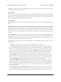
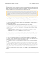
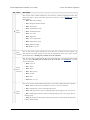
3.4. Errors
The Simple Motor Controller has several
features that stop the motor when
something is going wrong. These are called
errors, and they can help protect your
project from damaging itself. Whenever
you are having an issue with the controller,
you should first check to see what (if any)
errors are occurring. You can get
information about the errors by:
• Checking the Errors box in the Status
tab of the Simple Motor Control Center.
This is recommended because it gives
you the most information, including a
running count of how many times the
error has been reported.
• Running the command-line utility
(just type SmcCmd -s at the command
line).
• Looking at the red LED on the device.
It will be lit if there are any errors
stopping your motor.
• Writing PC software or using a
microcontroller to send the Get Errors
serial command.
The Errors box in the Status tab of the Pololu Simple
Motor Control Center reveals problems that are stopping
your motor.
• Using a microcontroller to measure
the voltage on ERR pin. This pin is linked to the red LED so it should go high (3.3 V) when there is an error
stopping your motor and low (0 V) otherwise.
All the errors are explained below:
• Safe start violation: Safe Start is a feature that helps prevent the motor from starting up unexpectedly.
This feature is enabled by default, but can be disabled in the Advanced Settings tab. The behavior of Safe
Start depends on what Input Mode you are using.
In Serial/USB input mode, the Safe start violation error occurs whenever any other error is stopping the
motor. After all the other errors have been fixed, you can clear the Safe start violation error by pressing the
Resume button (which issues a native USB command) or using a serial command.
In Analog or RC input mode, the Safe start violation error occurs whenever the motor is stopped because of
an error AND the inputs that control the speed of the motor are not near their neutral positions. This helps
prevent the situation where there might be an error stopping your motor (such as a disconnected battery),
and the motor starts running at a high speed when you fix the error. To clear the Safe start violation error,
move all the inputs that control the speed of the motor to their neutral positions (the sum of the absolute
values of their scaled values must be less than 8 %).
• Required channel invalid: This error occurs whenever any required RC or Analog channel is invalid.
This error helps ensure that your motor will stop if you accidentally disconnect your joystick, potentiometer
3. Getting Started
Page 20 of 108
Pololu Simple Motor Controller User’s Guide
© 2001–2015 Pololu Corporation
or RC receiver. A channel is invalid if it is disconnected, or has a value that is out of range. A channel is
required if it controls the speed of the motor or it is configured as a limit switch or kill switch. By default,
there are no required channels because the input mode is serial and no limit or kill switches have been
configured. You can check the Input Settings tab to see which channels are required. Channels that are
required and invalid are highlighted in red in the Input Channels box of the Status tab so you can quickly
see which channel is causing this error.
• Command timeout: This error occurs if you are controlling your motor using a microcontroller or a
PC (Input Mode is Serial/USB) and the (configurable) time period has elapsed with no valid serial or USB
commands being received by the controller. The purpose of this error is to ensure that your motor will stop
if the software talking to the controller crashes or if the communications link is broken. All valid serial
commands clear this error. The native USB commands for setting the speed and exiting safe start also clear
this error. By default, this error is disabled, but it can be enabled from the Advanced Settings tab by setting
a non-zero Command Timeout value.
• Limit/kill switch: This error occurs when a limit or kill switch channel stops the motor. More
specifically, it occurs in three cases: when a kill switch is active, when a Forward Limit switch is active
AND the Target Speed is positive, or when a Reverse Limit switch is active AND the Target Speed is
negative. A limit/kill switch is considered active if its scaled value is above 50 %. If you are using a limit
switch and your input mode is Serial/USB, you will need to check the Count column in the Status tab to see
this error because in Serial/USB mode the Target Speed gets set to 0 whenever there is an error.
• Low VIN: This error occurs whenever your power supply’s voltage is too low or it is disconnected.
If you set the correct thresholds in the Advanced Settings tab, this error will prevent you from overdischarging your battery.
• High VIN: This error occurs whenever your power supply’s voltage is too high. You can set the
threshold voltage in the Advanced Settings tab.
• Motor driver error: This error occurs whenever the motor driver chip reports an under-voltage or overtemperature error (by driving its fault line low).
• Over temperature: This error occurs whenever the reading from the temperature sensor is too high. You
can see the temperature reading in the Conditions box of the Status tab. The behavior of this error and the
threshold temperatures can be configured in the Advanced tab.
• ERR line high: This error occurs whenever there are no other errors but the voltage on the ERR line is
high (2.3–5 V). This error allows you to connect the error lines of two Simple Motor Controllers together
and have both of them stop when either one experiences an error. This error can be disabled in the Advanced
Settings tab.
• Serial errors: Serial errors are recorded whenever something goes wrong with the serial communication,
either on the RX/TX lines or on the USB virtual COM port. If the input mode is Serial/USB, then a serial
error will stop the motor from running until a valid serial command is received, or the Resume button is
pressed, or the native USB Set Speed or Exit Safe Start commands are sent. If you are using serial and
have not disabled Safe Start mode, you will need to send the Exit Safe-Start command, followed by a Set
Speed command to recover from an error and get the motor running again. If you are using serial and have
disabled Safe Start, the motor will start driving as soon when a valid Set Speed command is received. These
are the types of serial errors that are recorded:
◦ Frame: This is error occurs when a de-synchronization or excessive noise on the RX line is
detected.
◦ Noise: This error occurs when noise is detected on the RX line.
◦ RX overrun: This error occurs when the buffer for storing bytes received on the RX line is full and
data was lost as a result. This should not occur during normal operation.
3. Getting Started
Page 21 of 108
Pololu Simple Motor Controller User’s Guide
© 2001–2015 Pololu Corporation
◦ Format: This error occurs if the serial bytes received on RX or the virtual COM port do not obey
the protocol specified in this guide. If you get this error, check the bytes you are sending carefully, and
compare them to the examples provided.
◦ CRC: This error occurs if you have enabled cyclic redundancy check (CRC) for serial commands,
but the CRC byte received was invalid. CRC helps prevent the motor controller from accidentally
performing unwanted actions when it is receiving commands over a noisy serial link. If you get this
error, check your algorithm for calculating CRCs and check the quality of your serial signal at the RX
pin.
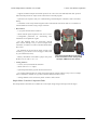
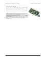
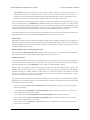
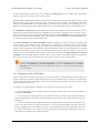
3.5. LED Feedback
The Simple Motor Controllers have three indicator LEDs that provide feedback about the current state of the
controller. The LEDs can tell you whether an error is occurring, whether the USB connection is active, what
direction the motor is driving, and much more.
Simple Motor Controller 18v7 LEDs.
Simple High-Power Motor Controller 18v15 or 24v12
LEDs.
3. Getting Started
Page 22 of 108
Pololu Simple Motor Controller User’s Guide
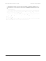
© 2001–2015 Pololu Corporation
Simple High-Power Motor Controller 18v25 or 24v23
LEDs.
The Simple Motor Controllers have three indicator LEDs:
Green USB LED
This LED indicates the USB status of the device. When the Simple Motor Controller is not connected to a
computer via the USB cable, the green LED will always be off. When you connect the controller to USB, the
green LED starts blinking slowly. The blinking continues until the controller receives a particular message from
the computer indicating that the Simple Motor Controller’s USB drivers are installed correctly (see Section 3.1
for driver installation instructions). After the controller gets this message, the green LED turns solidly on, except
for brief flickers whenever there is USB activity. The Simple Motor Control Center software constantly streams
data from the controller, so when the control center is running and connected to the Simple Motor Controller, the
green LED will flicker constantly.
Red Error LED
This LED turns on whenever there is an error stopping the motor (see Section 3.4 for information on errors that
can stop the motor). The red LED is tied directly to the active-high output ERR, which allows the error status to
be monitored by an external device such as a microcontroller. When no errors are stopping the motor, the error
LED is off and the ERR pin is pulled low. See Section 4.2 for more information about the ERR pin and the error
LED.
Yellow Status LED
This LED helps you visually identify the state of the device, which can be useful when the controller is not
connected to the Control Center. On start-up, the status LED briefly flashes a pattern indicating the source of the
last reset (see the Reset Flags variable in Section 6.4 for more information):
• 8 blinks over the first two seconds after start-up indicates that the external RST pin was driven low to
reset the controller.
• 3 blinks over the first two seconds after start-up indicates that the controller last reset because logic
power got too low (power was disconnected or the controller browned out).
• Rapid flickering for the first two seconds after start-up indicates that the controller was reset by a
software fault or by a firmware upgrade.
This startup behavior can help you detect if your Simple Motor Controller is browning out and resetting
unexpectedly (as can happen if your input voltage drops due to high power demands or electrical noise).
3. Getting Started
Page 23 of 108
Pololu Simple Motor Controller User’s Guide
© 2001–2015 Pololu Corporation
After the start-up phase ends, the status LED primarily gives feedback about the motor driver outputs:
• An even blinking pattern of on for 2/3 s and off for 2/3 s indicates that the controller is not driving
the motor and has not yet detected the baud rate. This pattern only occurs when the controller is in USB/
serial mode with automatic baud detection enabled and helps you determine when you have established
communication between a TTL serial source and the Simple Motor Controller.
• A brief flash once per second indicates that the controller is not driving the motor. If the controller is in
Serial/USB mode with automatic baud detection enabled, this pattern additionally indicates that the Simple
Motor Controller has successfully learned the TTL serial baud rate.
• A repeating, gradual increase in brightness every second indicates that the controller is driving the motor
forward.
• A repeating, gradual decrease in brightness every second indicates that the controller is driving the motor
in reverse.
3. Getting Started
Page 24 of 108
Pololu Simple Motor Controller User’s Guide
© 2001–2015 Pololu Corporation
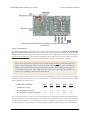
4. Connecting Your Motor Controller
This chapter explains all the electrical connections you might need to make to get your motor controller working
the way you want it to.
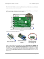
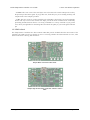
The diagrams below label the key components and pins on the Simple Motor Controllers. Most of these pins are
also labeled on the bottom side of the board.
• Simple Motor Controller 18v7 Pin-Out
4. Connecting Your Motor Controller
Page 25 of 108
Pololu Simple Motor Controller User’s Guide
© 2001–2015 Pololu Corporation
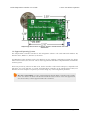
• Simple High-Power Motor Controller 18v15 and 24v12 Pin-Out
• Simple High-Power Motor Controller 18v25 and 24v23 Pin-Out
4. Connecting Your Motor Controller
Page 26 of 108
Pololu Simple Motor Controller User’s Guide
© 2001–2015 Pololu Corporation
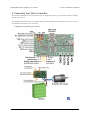
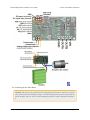
4.1. Connecting Power and a Motor
Warning: Take proper safety precautions when using high-power electronics. Make sure you know
what you are doing when using high voltages or currents! During normal operation, this product can
get hot enough to burn you. Take care when handling this product or other components connected to
it.
4. Connecting Your Motor Controller
Page 27 of 108
Pololu Simple Motor Controller User’s Guide
© 2001–2015 Pololu Corporation
The first step in using your Simple Motor Controller is connecting power and a motor. With those connections in
place, you can immediately start testing with the Simple Motor Control Center. The following section explains
the power system in detail.
Simple Motor Controller 18v7 power and motor connections.
Simple High-Power Motor Controller 18v15 or 24v12 power and motor
connections.
4. Connecting Your Motor Controller
Page 28 of 108
Pololu Simple Motor Controller User’s Guide
© 2001–2015 Pololu Corporation
Simple High-Power Motor Controller 18v25 or 24v23 power and motor
connections.
Power Considerations
The Pololu Simple Motor Controllers can be powered either from USB using a USB A to mini-B cable
[https://www.pololu.com/product/130] or from a power supply, such as a battery pack, connected to the large VIN and
GND pads. When the VIN supply is not present, the controller can use USB power to perform all of its functions
except for driving the motor. The controller automatically selects VIN as the power source when it is present,
even when USB is connected. It is OK to have both USB and VIN power simultaneously connected.
Power for the motor must be supplied to the controller through the large VIN and GND pads. The
smaller VIN and GND pads on the left side of the board in the diagrams above are not suitable for
high currents and should not be used to power the motor controller. These smaller power pins provide
a convenient way to pass the input voltage on to other parts in your system, but they should not be
used to power anything that will draw more than 500 mA.
All Simple Motor Controller versions can operate from VIN supplies as low as 5.5 V, but the maximum
continuous output current will be lower for voltages under 7 V. The maximum power ratings for the Simple
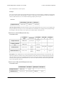
Motor Controllers are shown below:
Simple Motor Controller
18v7
18v15
24v12
18v25
24v23
Absolute max voltage
30 V
30 V
40 V
30 V
40 V
Recommended max voltage
24 V
24 V
34 V
24 V
34 V
Max continuous current w/o heat sink
7A
15 A
12 A
25 A
23 A
It is very important that you select a power source that does not exceed the absolute maximum voltage rating for
your Simple Motor Controller. Ripple voltage on the supply line can raise the maximum voltage to more than the
average or intended voltage, so we recommend you to select a voltage that leaves at least a 6 V margin for noise.
It is also important to note that batteries can be much higher than their nominal voltage when fully charged, so
4. Connecting Your Motor Controller
Page 29 of 108
Pololu Simple Motor Controller User’s Guide
© 2001–2015 Pololu Corporation
we do not recommend using the 18v7, 18v15, or 18v25 versions with 24 V batteries unless appropriate measures
are taken to limit the peak voltage.
For 24 V applications, we recommend the 24v12 or 24v23 versions. We strongly recommend against
using the 18v7, 18v15, or 18v25 with 24 V batteries, which can significantly exceed 24 V when fully
charged and are dangerously close to the maximum voltage limits of these lower-voltage controllers.
Using a 24 V battery with an 18vX Simple Motor Controller makes the device much more susceptible
to damage from power supply noise or LC voltage spikes.
Finally, make sure you select a power source that is capable of delivering the current your motor will require
(e.g. alkaline cells are typically poor choices for high-current applications), and place a large capacitor across
power and ground near the motor controller to limit electrical noise (such a capacitor is pre-installed on fullyassembled 18v7, 18v15, and 24v12 controller versions).
The Simple Motor Controllers feature a configurable low-voltage shutoff that can help you avoid
damaging batteries that are sensitive to over-discharging, such as Li-Po packs. See Section 5 for
more information.
Motor Considerations
The two terminals of your brushed, DC motor connect to the OUTA and OUTB pins. When selecting a motor
for your controller (or a controller version for your motor), it is important to consider how the motor will be
used in your system. If the motor is likely to be stalled for prolonged periods of time or under heavy load, or
if the motor will be rapidly changing direction without acceleration limiting enabled, you should be taking into
4. Connecting Your Motor Controller
Page 30 of 108
Pololu Simple Motor Controller User’s Guide
© 2001–2015 Pololu Corporation
account the stall current of the motor at the voltage it will be running and selecting a controller that can deliver
a continuous current that exceeds the stall current.
It is not unusual for the stall current of a motor to be an order of magnitude (10×) higher than
its free-run current. When a motor is supplied with full power from rest, it briefly draws the full
stall current, and it draws nearly twice the stall current if abruptly switched from full speed in one
direction to full speed in the other direction.
Occasionally, electrical noise from a motor can interfere with the rest of the system. This can depend on a number
of factors, including the power supply, system wiring, and the quality of the motor. If you notice parts of your
system behaving strangely when the motor is active (e.g. corrupted serial data, bad RC pulses, noisy analog
voltage readings, or the motor controller randomly resetting), consider taking the following steps to decrease the
impact of motor-induced electrical noise on the rest of your system:
1. Solder a 0.1 µF ceramic capacitor [https://www.pololu.com/product/1166] across the terminals of your
motor, or solder one capacitor from each terminal to the motor case. For the greatest noise suppression, you
can use three capacitors (one across the terminals and one from each terminal to the case).
2. Make your motor leads as thick and as short as possible, and twist them around each other. It is also
beneficial to do this with your power supply leads.
3. Route your motor and power leads away from your logic connections if possible.
4. Place decoupling capacitors (also known as “bypass capacitors”) across power and ground near any
electronics you want to isolate from noise.
Power and Motor Connectors
Simple Motor Controller
18v7, fully assembled.
Simple High-Power Motor
Controller 18v15 or 24v12,
fully assembled.
Simple High-Power Motor
Controller 18v25 or 24v23
with included hardware
installed.
The fully-assembled 18v7, 18v15, and 24v12 Simple Motor Controller versions ship with terminal blocks
soldered into the large VIN, OUTA, OUTB, and GND pads and a power capacitor pre-installed, as shown in the
pictures above. These terminal blocks make it easy to connect and disconnect power supplies, but they are only
rated for 15 A.
4. Connecting Your Motor Controller
Page 31 of 108
Pololu Simple Motor Controller User’s Guide
Simple High-Power Motor Controller
18v15 or 24v12, partial kit with
included hardware.
Simple High-Power Motor Controller
18v15 or 24v12, partial kit with
custom power and motor connectors
(NOT included).
© 2001–2015 Pololu Corporation
Simple High-Power Motor Controller
18v25 or 24v23 with included
hardware.
Simple High-Power Motor Controller
18v25 or 24v23 with custom power
and motor connectors (NOT included).
All other versions ship with terminal blocks and a power capacitor included but not installed, which provides
flexibility in making connections. These versions offer two options for connecting to the high-power signals
(VIN, OUTA, OUTB, GND): large holes on 0.2" centers, which are compatible with the included terminal
blocks [https://www.pololu.com/product/2440], and pairs of 0.1"-spaced holes, which are compatible with the included
0.1" male header strip [https://www.pololu.com/product/965] and can be used with perfboards, breadboards
[https://www.pololu.com/category/28/solderless-breadboards], and 0.1" connectors. For high-power applications that
exceed the 15 A rating of the terminal blocks, we recommend soldering thick wires directly to a connector-free
version of the board and using higher-current connectors [https://www.pololu.com/product/925] (see the customconnector pictures above). Another benefit of the connector-free version is flexibility in placement of the power
capacitor (e.g. on the other side of the board) to accommodate compact installations or to make room for a heat
sink. The power capacitor has a significant effect on performance; the included capacitor is the minimum size
recommended, and bigger ones can be added if there is space. A bigger capacitor might be required if the power
supply is poor or far (more than about a foot) from the controller. The pin-out diagrams above show where you
can connect the included (or your own larger) power capacitor.
4. Connecting Your Motor Controller
Page 32 of 108
Pololu Simple Motor Controller User’s Guide
© 2001–2015 Pololu Corporation
Logic Power
The Simple Motor Controllers use 3.3 V logic, but all of the controllers’ digital inputs are 5V-tolerant, so it can
interface directly with 5V systems. The only pins on the board that cannot tolerate 5V are the two analog input
channels, A1 and A2. The simple motor controllers incorporate both a 5V regulator and a 3.3V regulator, but
the 5V regulator is only used when power is supplied to VIN. Otherwise, the USB 5V bus voltage replaces the
output of the 5V regulator. The 5V and 3.3V power buses are available via the RC BEC jumper pads (see the
upper-right corners of the power connection diagrams above), and a shorting block can be used to connect the
RC power row to the desired voltage rail, thereby powering a connected RC receiver with 3.3 or 5 V. These pins
can also be used to supply approximately 150 mA to other components in your system.
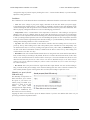
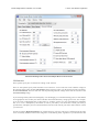
Trying Out the Controller with USB
Once you have a connected a power supply and a motor, you can use the Simple Motor Control Center to
make the motor move and test how various settings affect the behavior of the motor (see Section 5 for more
information on configuring the Simple Motor Controller). The Simple Motor Controller defaults to “Serial/USB”
input mode, which lets you control the motor speed with the slider bar under the status tab. If you have already
changed the input mode of the device to something else, you can restore it by going to the Input Settings tab,
selecting Serial/USB as the Input Mode, and clicking the Apply Settings button in the lower right corner.
Status tab in the Pololu Simple Motor Control Center.
4. Connecting Your Motor Controller
Page 33 of 108
Pololu Simple Motor Controller User’s Guide
© 2001–2015 Pololu Corporation
Before you can move the motor, you will probably need to click the green Resume button in the lower left corner
to clear the safe-start violation. If the Resume button is grayed out, there are errors that are preventing the motor
from moving. See Section 3.4 for information on how to identify and fix errors.
Safe Start is an optional feature, enabled by default, that makes it less likely that the motor will
start moving unexpectedly.
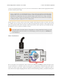
4.2. Connecting a Serial Device
The serial pins make it possible to connect the Simple Motor Controller to a microcontroller (e.g. an Orangutan
Robot Controller [https://www.pololu.com/category/8/robot-controllers], Arduino [https://www.pololu.com/product/2191], or
Basic Stamp [https://www.pololu.com/product/1600]) or other logic-level serial device, allowing for the creation of
autonomous, self-contained systems. The following section explains the serial pins in detail (see Section 6 for
information on using the serial interface).
Simple Motor Controller 18v7 serial connections.
Simple High-Power Motor Controller 18v15 or 24v12 serial connections.
4. Connecting Your Motor Controller
Page 34 of 108
Pololu Simple Motor Controller User’s Guide
© 2001–2015 Pololu Corporation
Simple High-Power Motor Controller 18v25 or 24v23 serial connections.
Serial Connections Overview
The pins along the left side of the Simple Motor Controller can be used to communicate with devices with logiclevel (TTL) serial interfaces, such as microcontrollers. As explained in Section 4.1, the Simple Motor Controller
uses 3.3V logic, but all of the digital pins in the above diagrams (everything except for VIN and GND) are 5Vtolerant, which means that the Simple Motor Controller can be used directly with a microcontroller running at
5 V as long as that microcontroller is guaranteed to read a 3.3 V signal as high.
The Simple Motor Controller uses its RX and TX pins to receive and transmit asynchronous, logic-level (TTL),
non-inverted serial signals with 8-bit characters and one stop bit (often expressed as 8-N-1). This is the type of
serial typically used by microcontroller UART modules.
Whenever connecting devices, remember to wire the grounds together, and ensure that each
device is properly powered. Unpowered devices with a TTL serial port can turn on or partially
on, drawing power from the serial line, which means that extra care must be taken when turning
power off and on to reset the devices.
Note: You must use an inverter and level shifter such as a MAX232 or a Pololu 23201a Serial
Adapter [https://www.pololu.com/product/126] if you want to interface an RS-232 device with the Simple
Motor Controller. Connecting an RS-232 device directly to the Simple Motor Controller can
permanently damage it.
4. Connecting Your Motor Controller
Page 35 of 108
Pololu Simple Motor Controller User’s Guide
© 2001–2015 Pololu Corporation
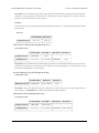
Serial Interface Pin Descriptions
Pin
Direction
Description
RX
Input
Simple Motor Controller TTL serial receive pin. This should be connected to
the TTL serial output (transmit line) of your other device. This connection is
only required if you want to send serial commands to the motor controller from
your other device.
TX
Output
Simple Motor Controller TTL serial transmit pin. This should be connected to
the TTL serial input (receive line) of your other device. This connection is only
required if you want to receive serial feedback from the motor controller.
RST
Input
Simple Motor Controller active-low reset pin. This pin is internally pulled high;
driving it low resets the motor controller. You must wait for at least 1 ms after a
reset to transmit to the Simple Motor Controller. This pin can be left
disconnected in most applications.
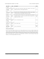
ERR
In/Out
Simple Motor Controller error output. This pin outputs high when there is an
error that is stopping the motor, turning on the red error LED in the process;
otherwise, it is weakly pulled low. This pin is documented in more detail below.
Input
Simple Motor Controller chained transmission input pin. Connecting the
transmit output of another serial device to this pin will cause that device’s
transmissions to be output from the Simple Motor Controller’s TX pin. This pin
is documented in more detail below.
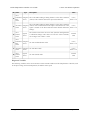
TXIN
GND
Ground connection point. Your serial device must share a common ground with
the Simple Motor Controller.
VIN
Board power access point. This pin is internally connected to the large VIN pad
where motor power is supplied and can be used to power other components in
the system, but it should not be used to supply more than 500 mA. This is not a
regulated, logic-level output.
Output
These pins have a 0.1" spacing.
Simple Wiring Example: Connecting to a Microcontroller
All you need to control the Simple Motor Controller with a microcontroller is a connection between the
microcontroller’s TTL serial transmit pin and the Simple Motor Controller’s RX pin. If you want to get feedback
from the controller, you can connect the TX pin to the microcontroller’s TTL serial receive pin and/or connect
the ERR pin to one of the microcontroller’s digital inputs. Connecting one of the microcontroller’s digital
outputs to the RST pin allows the microcontroller to selectively reset the Simple Motor Controller.
4. Connecting Your Motor Controller
Page 36 of 108
Pololu Simple Motor Controller User’s Guide
© 2001–2015 Pololu Corporation
The ERR Pin in Detail
One function of the ERR pin is to communicate that an error is preventing the motor from moving. When such
an error occurs, the red error LED turns on and the ERR pin outputs 3.3 V. When there are no errors stopping
the motor, the ERR pin is pulled low and the red error LED is off. Because the ERR pin never drives low, it
is safe to connect the ERR pins of multiple Simple Motor Controllers to the same microcontroller input. If any
one of those controllers experiences an error, the microcontroller error input goes high and the error LEDs of all
connected Simple Motor Controllers light up.
By default, the ERR pin is also configured to serve as an input that stops the motor when externally driven
above 2.3 V. This means that the error lines of multiple Simple Motor Controllers can be connected together
and all motor controllers will shut down their motors when any one motor controller experiences an error. This
technique of connecting error lines can be used even when RC signals or analog voltages are used to control the
motors. An example of this can be seen in Section 4.3.
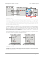
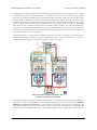
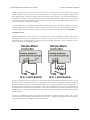
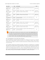
The following diagrams show the internal circuitry of the ERR pin in the error case (driving high to report an
error) and in the error-free case (pulled low and configured as an input):
Schematic diagram of the Simple
Motor Controller ERR pin when the pin
is an output (i.e. there are errors).
Schematic diagram of the Simple
Motor Controller ERR pin when the pin
is an input (i.e. there are no errors).
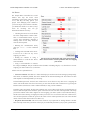
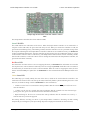
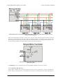
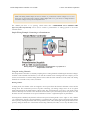
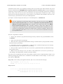
The TXIN Pin in Detail
The TXIN pin is a special input that allows multiple Simple Motor Controllers to be chained together without
requiring an external AND gate. The following diagram shows how multiple motor controllers can be connected
to a single microcontroller UART:
4. Connecting Your Motor Controller
Page 37 of 108
Pololu Simple Motor Controller User’s Guide
© 2001–2015 Pololu Corporation
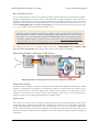
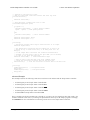
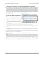
Wiring diagram for controlling multiple Simple Motor Controllers with single TTL serial source,
such as a microcontroller.
Inside each Simple Motor Controller, an AND gate is used to combine the input from the TXIN pin with the
controller’s serial transmissions. As long as only one chained controller is transmitting at any given time, the
above method of chaining will funnel the transmissions of all chained devices to a single microcontroller receive
line. The following diagram shows the internal circuitry of the TX and TXIN pins:
Schematic diagram of the Simple Motor Controller
TXIN and TX pins.
See Section 6.6 for more information on connecting multiple controllers on the same serial line.
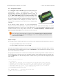
4.3. Connecting an RC Receiver
Simple Motor Controller can be directly connected to an RC receiver, allowing for wireless, manual motor
control. The RC inputs can serve several functions, from directly controlling the motors (RC input mode) to
4. Connecting Your Motor Controller
Page 38 of 108
Pololu Simple Motor Controller User’s Guide
© 2001–2015 Pololu Corporation
sending signals to an autonomous robot (Serial/USB mode) to providing an RC kill switch (any input mode).
The Simple Motor Controller can derive motor speed from a single RC input channel, or it can mix the signals on
both RC channels to generate the motor speed, which makes intuitive throttle+steering control of a differentialdrive robot possible using a pair of Simple Motor Controllers. A BEC jumper lets the Simple Motor Controller
optionally power your RC receiver at 3.3 or 5 V, eliminating the need for a second battery.
Simple Motor Controller 18v7 RC connections.
Simple High-Power Motor Controller 18v15 or 24v12 RC connections.
Simple High-Power Motor Controller 18v25 or 24v23 RC connections.
4. Connecting Your Motor Controller
Page 39 of 108
Pololu Simple Motor Controller User’s Guide
© 2001–2015 Pololu Corporation
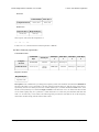
RC Connections Overview
The RC connection block consists of two channels oriented as columns and a battery elimination circuit (BEC)
column for supplying power to the RC receiver. Each channel has a ground pin (outlined in black in the above
diagrams), a power pin (outlined in red in the above diagrams), and a signal pin (outlined in yellow in the above
diagrams). The RC signal pins can read standard hobby servo RC pulses with peaks anywhere from 2 to 5 V. The
included shorting block [https://www.pololu.com/product/968] can be used to supply the power pin row with either
3.3 V or 5 V, which in turn can be used to power an RC receiver.
Note: If you want to connect servos directly to your RC receiver, you must power it separately as
the Simple Motor Controller’s regulators cannot supply enough current to power a servo. If your
RC receiver is powered separately, you must leave the BEC jumper off to avoid shorting the motor
controller’s regulated voltage to your RC receiver’s power source. Your receiver and Simple Motor
controller must always have a common ground, even if you power the RC receiver separately.
The channel pins have a 0.1" spacing, which means that a female-female servo extension cable
[https://www.pololu.com/product/780] can be used to connect an RC receiver directly to the board.
Simple Wiring Example: Connecting to an RC Receiver
Wiring diagram for connecting an RC receiver to a Simple Motor Controller.
Using the RC Channels
The Simple Motor Controller is constantly reading the two RC channels and making the measured pulse widths
available via the USB and serial interfaces, even when the controller is not in RC mode. For example, you can
use the serial interface to read the RC channel values while the motor controller is in analog mode. The RC
channels are read with 0.25 µs resolution, and RC pulse frequencies from 10 Hz to 333 Hz are permitted. A
number of settings exist for adjusting what constitutes a valid RC signal.
Driving a Motor
In RC mode, the channel values are mapped to motor speed based on the channel calibration values and the
mixing mode. We recommend your first step after connecting your RC receiver be to use the Quick Input Setup
wizard in the Simple Motor Control Center. The wizard instructs you to move your transmitter control sticks
to their extremes and maps stick full forward/right to the maximum forward motor speed, the neutral stick to
speed zero, and the stick full back/left to maximum reverse speed. Calibration can have a significant impact on
performance.
4. Connecting Your Motor Controller
Page 40 of 108
Pololu Simple Motor Controller User’s Guide
© 2001–2015 Pololu Corporation
If mixing mode is disabled, only channel 1 affects motor speed. If mixing mode is set to “right” or “left”, channel
1 is considered the “throttle” input and channel 2 is considered the “steering” input. Left mixing mode obtains
motor speed by summing the throttle and steering channels (CH1+CH2) while right mixing mode obtains motor
speed by taking the difference of the throttle and steering channels (CH1-CH2). To see why this makes sense,
consider a differential-drive robot (a robot with a motor on each side) with a left motor driven by a Simple
Motor Controller in left mixing mode and a right motor driven by a Simple Motor Controller in right mixing
mode. When throttle is full forward (CH1=max) and steering is neutral (CH2=0), left- and right-mixed motors
are both driven forward at full speed and the robot goes forward. When throttle is neutral (CH1=0) and steering
is full right (CH2=max), the left mixing results in motor forward at full speed while right mixing results in motor
reverse at full speed, so the robot turns right.
As demonstrated above, using both RC channels in mixing mode makes it possible to combine two RCcontrolled Simple Motor Controllers to achieve single-stick (mixed) control of a differential drive robot. The
following diagram shows how to connect two such motor controllers together:
Wiring diagram for pairing two Simple Motor
Controllers with RC channel mixing.
You should configure the controller that drives the right motor as “mixing mode right” and the controller that
drives the left motor as “mixing mode left”. You can splice together your own cables or use premade Y splitter
cables [https://www.pololu.com/product/2164] to connect channels 1 and 2 from your RC receiver to channels 1 and
2 of both controllers as shown in the diagram above. You can also connect the ERR lines of both controllers
together to ensure that both controllers stop if either controller experiences an error. The following pictures show
4. Connecting Your Motor Controller
Page 41 of 108
Pololu Simple Motor Controller User’s Guide
© 2001–2015 Pololu Corporation
a Wild Thumper 4WD chassis [https://www.pololu.com/product/1567] being driven by two Simple Motor Controllers
in mixed RC mode as depicted in the above wiring diagram:
Limit/Kill Switches
Unused RC channels can also be used as limit or kill switches. For example, you could use an RC signal as a
kill switch to stop your autonomous, serially-controlled robot if it gets into trouble. When configured as a limit
or kill switch, if the channel’s value exceeds more than half of its “forward” value, the switch is activated. We
recommend you use the Channel Setup Wizard (click the “Learn…” button in the Simple Motor Control Center)
for any RC channel you configure as a limit or kill switch.
4.4. Connecting a Potentiometer or Analog Joystick
Simple Motor Controller can be directly connected to a 0 to 3.3 V analog voltage source, such as a potentiometer
or analog joystick, allowing for simple manual motor control (e.g. easily control motor speed with a knob). The
analog inputs can serve several functions, from directly controlling the motors (Analog input mode) to sending
signals to an autonomous robot (Serial/USB mode) to providing limit or kill switch inputs (any input mode).
The Simple Motor Controller can derive motor speed from a single analog input channel, or it can mix the
signals on both analog channels to generate the motor speed, which makes intuitive throttle+steering control of
a differential-drive robot possible using a pair of Simple Motor Controllers. Typical analog voltage sources can
be powered directly from the Simple Motor Controller.
Simple Motor Controller 18v7 analog connections.
4. Connecting Your Motor Controller
Page 42 of 108
Pololu Simple Motor Controller User’s Guide
© 2001–2015 Pololu Corporation
Simple High-Power Motor Controller 18v15 or 24v12 analog
connections.
Simple High-Power Motor Controller 18v25 or 24v23 analog connections.
Analog Connections Overview
The analog connection block consists of two channels. Each channel has a signal pin and a + and – pin for
powering the analog voltage source. These potentiometer power pins are special in that they allow the Simple
Motor Controller to detect if an analog channel has become disconnected, so we recommend using these pins
rather than alternate power supplies or other pins on the board.
If you use an analog voltage source that is not powered from the Simple Motor Controller’s
potentiometer power (+ and –) pins, you will need to check the Ignore Pot Disconnect checkbox
under the Advanced Settings tab of the Simple Motor Control Center (see Section 5.3).
We recommend using a potentiometer in the 1 kΩ to 10 kΩ range. Higher-resistance potentiometers will not
work well with the potentiometer disconnection detection feature. If you need to use a higher-resistance
potentiometer, you can disable potentiometer disconnection detection from the Simple Motor Control Center.
4. Connecting Your Motor Controller
Page 43 of 108
Pololu Simple Motor Controller User’s Guide
© 2001–2015 Pololu Corporation
Note: The analog channel inputs are not 5V tolerant, so you must not connect voltages over 3.3 V to
these pins. If your control source outputs voltages higher than 3.3 V, you can use a voltage divider to
ensure the voltage is always at an acceptable level.
The channel pins have a 0.1" spacing, which means that a female-female servo extension cable
[https://www.pololu.com/product/780] can be used to connect a potentiometer or analog joystick to the motor
controller board.
Simple Wiring Example: Connecting to a Potentiometer
Wiring diagram for connecting a potentiometer or joystick to a
Simple Motor Controller.
Using the Analog Channels
The Simple Motor Controller is constantly sampling the two analog channels and making the measured voltages
available via the USB and serial interfaces, even when the controller is not in analog mode. For example, you can
use the serial interface to read the analog channel values while the motor controller is in RC mode. The analog
channels are read with 12-bit (0.8 mV) resolution.
Driving a Motor
In analog mode, the channel values are mapped to motor speed based the channel calibration values and the
mixing mode. We recommend your first step after connecting your analog voltage source be to use Quick
Input Setup Wizard in the Simple Motor Control Center. The wizard instructs you to move your inputs to their
extremes and maps one extreme to the maximum forward motor speed, the neutral position to speed zero, and
the other extreme to maximum reverse speed. Calibration can have a significant impact on performance.
If mixing mode is disabled, only channel 1 affects motor speed. If mixing mode is set to “right” or “left”, channel
1 is considered the “throttle” input and channel 2 is considered the “steering” input. Left mixing mode obtains
motor speed by summing the throttle and steering channels (CH1+CH2) while right mixing mode obtains motor
speed by taking the difference of the throttle and steering channels (CH1-CH2). To see why this makes sense,
4. Connecting Your Motor Controller
Page 44 of 108
Pololu Simple Motor Controller User’s Guide
© 2001–2015 Pololu Corporation
consider a differential-drive robot (a robot with a motor on each side) with a left motor driven by a Simple
Motor Controller in left mixing mode and a right motor driven by a Simple Motor Controller in right mixing
mode. When throttle is full forward (CH1=max) and steering is neutral (CH2=0), left- and right-mixed motors
are both driven forward at full speed and the robot goes forward. When throttle is neutral (CH1=0) and steering
is full right (CH2=max), the left mixing results in motor forward at full speed while right mixing results in motor
reverse at full speed, so the robot turns right.
As demonstrated above, using both analog channels in mixing mode makes it possible to combine two joystickcontrolled Simple Motor Controllers to achieve single-stick (mixed) control of a differential drive robot. The
connection diagram for such a setup would be very similar to the RC-mixing diagram shown in Section 4.3.
Limit/Kill Switches
Unused analog channels can also be used as limit or kill switches. When configured as a limit or kill switch, if
the channel value exceeds more than half of its “forward” value, the switch is activated. If you want to use a
push-button switch for this purpose, we recommend using a normally closed (NC) switch connected in one of
the two ways depicted in the diagrams below:
By using a normally closed limit switch, you ensure that if the switch becomes disconnected in some way, the
controller considers the limit/kill switch active and stops the motor. The left wiring diagram is simpler because it
uses an internal pull-up resistor (enabled using the Simple Motor Control Center), but it can only result in one of
two possible states: switch active or switch inactive. The right wiring diagram above is able to take advantage of
the potentiometer disconnection detection feature. Pressing the switch activates it, releasing it deactivates it, and
disconnecting it results in a disconnection error or an activated switch, depending on which parts of the switch
are disconnected.
The above configurations should work with the default analog channel calibration values, but we still
recommend you use the Channel Setup Wizard (click the “Learn…” button in the Simple Motor Control Center)
for any analog channel you configure as a limit or kill switch.
4. Connecting Your Motor Controller
Page 45 of 108
Pololu Simple Motor Controller User’s Guide
© 2001–2015 Pololu Corporation
Normally open (NO) switches can also be used as limit/kill switches with this controller, but they are not as safe
since accidental disconnection will lock the switch in an inactive state.
4. Connecting Your Motor Controller
Page 46 of 108
Pololu Simple Motor Controller User’s Guide
© 2001–2015 Pololu Corporation
5. Configuring Your Motor Controller
The Simple Motor Controllers can be configured over USB using the Pololu Simple Motor Control Center,
which is available for download from the Pololu website (see Section 3.1).
5.1. Input Settings
The Input Settings tab of the Pololu Simple Motor Control Center allows you to quickly specify how you want
to control the speed of the motor, and also allows you to set up limit and kill switches.
As a first step, we recommend that you click “Quick Input Setup…”. This will launch the Quick Input Setup
Wizard, which will let you specify how you want to control of the motor, and (if you are using analog or RC)
lets you quickly calibrate your inputs. When you finish the Quick Input Setup Wizard, your new settings will
get saved in the Input Settings tab and will (optionally) be applied to the device so you can start using your new
settings right away. After you are done running the Quick Input Setup, you should be able to successfully control
your motor, as long as you have made all the necessary electrical connections as described in Section 4.
The rest of this section documents all of the Input Settings in detail. If you are able to control the motor the way
you want to after running the Quick Input Setup Wizard, then you probably don’t need to read this section.
The serial settings in the Input Settings tab are not documented here. If you want to use the serial
interface, please see Section 6.
5. Configuring Your Motor Controller
Page 47 of 108
Pololu Simple Motor Controller User’s Guide
© 2001–2015 Pololu Corporation
Input Settings tab in the Pololu Simple Motor Control Center.
Input Mode
The Input Mode specifies what kind of input the controller will use to calculate the Target Speed of the motor.
The available options are:
• Serial/USB: In this input mode, the Target Speed is specified by serial or USB commands, and the Target
Speed is reset to zero whenever there is an error. This is the default input mode.
• Analog: In this input mode, the Target Speed is determined by the voltages measured on the analog
signal lines (A1 and optionally A2 if you want to use mixing).
• RC: In this input mode, the Target Speed is determined by the pulse widths measured on the RC signal
lines (RC1 and optionally RC2 if you want to use mixing).
Regardless of which input mode you choose, the Analog and RC input channels will always be measured; those
channels can be used as limit or kill switches if they are not controlling the speed of the motor and their values
can be retrieved using the Get Variable serial command.
Mixing Mode
If you have chosen Analog or RC as the Input Mode, the Mixing Mode setting specifies whether to use mixing
and what type of mixing it is.
5. Configuring Your Motor Controller
Page 48 of 108
Pololu Simple Motor Controller User’s Guide
© 2001–2015 Pololu Corporation
The primary use of mixing is for controlling a motor on a differential drive robot. You can use one Simple Motor
Controller for each motor on the robot, and feed the same inputs in to both of them. We recommend connecting
the throttle (forward/reverse) input to channel 1, and the steering (left/right) input to channel 2.
• None: In this mixing mode, the Target Speed is calculated as a function of the Scaled Value of the first
channel only (Analog Channel 1 or RC Channel 1).
• Left (+): In this mixing mode, the Target Speed is calculated as a function of the sum of the Scaled Value
of both channels.
• Right (-): In this mixing mode, the Target Speed is calculated as a function of the difference of the
Scaled Value of both channels (channel 1 minus channel 2).
Note that in RC and Analog mode, the Target Speed depends not only on the Scaled Values of the channels, but
also on the Starting Speed and Max Speed parameters, as explained in Section 5.2.
The table below summarizes all the input and mixing modes you can choose:
Input
Mode
Mixing
Mode
Motor speed is calculated
from…
Example Applications
Serial/
USB
N/A
Serial and/or USB commands
Motor controlled by microcontroller
or PC.
Analog
None
Analog Channel 1
Motor controlled by joystick.
Analog
Left (+)
Analog Channel 1 plus Analog
Channel 2
Differential drive vehicle controlled
by joystick.
Analog
Right (-)
Analog Channel 1 minus Analog
Channel 2
Differential drive vehicle controlled
by joystick.
RC
None
RC Channel 1
Electronic Speed Controller (ESC).
RC
Left (+)
RC Channel 1 plus RC Channel 2
Differential drive RC vehicle.
RC
Right (-)
RC Channel 1 minus RC Channel
2
Differential drive RC vehicle.
The settings on the bottom half of the Input Settings tab are all channel-specific settings. To view or edit them,
you must first select the desired channel using the list box in the bottom left corner.
Alternate Use
The Alternate Use setting allows you to configure any channel that is not used to control the speed of the motor
as a limit or kill switch. The available options are:
• None: This channel will not be used for anything special, but its Raw and Scaled values can be read
using serial or USB.
• Forward limit switch: When the scaled value of the channel is above 1600 (50%), the limit switch will
be considered active and the motor will not be allowed to move forward. If the target speed is positive, a
“Limit/kill switch” error will occur.
• Reverse limit switch: When the scaled value of the channel is above 1600 (50%), the limit switch will
be considered active and the motor will not be allowed to move in reverse. If the target speed is negative, a
“Limit/kill switch” error will occur.
5. Configuring Your Motor Controller
Page 49 of 108
Pololu Simple Motor Controller User’s Guide
© 2001–2015 Pololu Corporation
• Kill switch: When the scaled value of the channel is above 1600 (50%), the kill switch will be
considered active and the “Limit/kill switch” error will occur, preventing the motor from moving. For
example, you could use the kill switch feature and the Serial/USB input mode to make an autonomous robot
that you can conveniently immobilize from a distance using an RC transmitter and receiver.
The Forward and Reverse Limit Switch options allow you to set up limits that prevent your actuator from moving
out of its allowed range. See Section 4.4 for information about connecting limit switches. You will probably
want to avoid setting a motor deceleration limit if you are using a limit switch, because the deceleration limit will
prevent the motor from stopping immediately: when the switch is triggered, the motor will gradually decelerate
from its current speed to zero, which might be bad for your system depending on how it is set up.
Any channel configured as a limit or kill switch is considered a required channel. This means that the motor will
stop if that channel becomes disconnected (the Required channel invalid error will occur).
Learn button
The Learn… button launches the Channel Setup Wizard, which lets you quickly calibrate your input channel or
limit switch. Before using this wizard, you should select your desired Alternate Use and if you are configuring
an analog channel then you should first enable the pull-up resistor and check “Ignore Pot Disconnect” in the
Advanced Settings tab if necessary.
Enable pull-up resistor (analog channels only)
When checked, the Enable pull-up resistor option enables a pull-up resistor on the selected analog input line.
The value of the resistor is approximately 40 kΩ and it pulls the line up to 3.3 V.
Scaling Parameters
The rest of channel-specific settings are all scaling parameters, which means they specify how the Scaled Value
of the input channel is calculated from its Raw Value. They also specify the normal range of the input channel.
All of these parameters except Scaling degree can be easily set using the Learn… button.
The Raw Value of a channel is measured directly from the input pin. For RC channels, the Raw Value is the
width of received pulses in units of 1/4 μs; typical RC receivers will generate signals between 4000 (1000 μs)
and 8000 (2000 μs). For Analog channels, the Raw Value is a 12-bit measurement of the voltage on the input
line: 0 is 0 V and 4095 is 3.3 V. You can see the raw value of the selected channel by looking at the “Current
channel value” label or by looking at the Status tab.
If the Raw Value is less than Error min or greater than Error max, then the channel is considered invalid and the
Scaled Value is not computed. Otherwise, the Scaled Value of a channel is calculated from the Raw Value using
the scaling parameters. Specifically:
• Raw values between Error min. and Minimum map to a Scaled Value of -3200 (or 3200 if “Invert input
direction” is checked).
• Raw values between Minimum and Neutral minimum map to a Scaled Value between -3200 (or 3200
if “Invert input direction” is checked) and 0.
• Raw values between Neutral minimum and Neutral maximum map to a Scaled Value of 0.
• Raw values between Neutral maximum and Maximum map to a Scaled Value between 0 and 3200 (or
-3200 if “Invert input direction” is checked).
• Raw values between Maximum and Error max. map to a Scaled Value of 3200 (or -3200 if “Invert
input direction” is checked).
5. Configuring Your Motor Controller
Page 50 of 108
Pololu Simple Motor Controller User’s Guide
© 2001–2015 Pololu Corporation
By default, the scaling is linear, but you can change the Scaling degree to use a higher-degree polynomial
function, which gives you better control for low speeds.
The Error min. and Error max. parameters should be set so that the input channel’s Raw Value is always within
that range whenever the input is operating properly. One way to do this is to move your input to the minimum
position, and set Error min. to be 10–200 counts lower than the current channel value. Similarly, move your
input to its maximum position, and set Error max. to be 10–200 counts higher than the current channel value.
The Minimum and Maximum parameters should be as far apart as possible to maximize the accuracy of your
speed control, but they should still be close enough that you can reliably reach scaled values of ±3200 (±100 %).
One way to do this is to move your input to its minimum position, and set Minimum to be 10–200 counts higher
than the current channel value. Similarly, move your input to its maximum position, and set Error max. to be
10–200 counts lower than the current channel value.
The Neutral minimum and Neutral maximum parameters should be as close as possible to maximize the
accuracy of your speed control, but they should still be far enough from eachother so that you can reliably
reach a scaled value of 0 when you put your input in the neutral position (e.g. release your finger from the
joystick). Some joysticks can settle at different positions depending on where you release the from, so you should
experiment with releasing your joystick from different positions and see what Raw Values you get (you can
see them using “Current channel value” label or in the Status tab). Then set Neutral minimum and Neutral
maximum so that their range includes all of the values you saw, and has a reasonable margin. This guarantees
that you will not waste any power driving your motor when your stick is in the neutral position.
If you want to restrict the scaled value of the channel to always be negative or always be positive,
you can set the Minimum equal Neutral Minimum or you can set Maximum equal to Neutral
Maximum. This could be useful for one-directional control of a motor but typical applications
will not need this.
5.1.1. Configuring a Limit or Kill Switch
Limit switches and kill switches help protect your motor controller from performing unwanted actions. For
example, analog limit switches could be configured to prevent your actuator from moving out of its valid range.
An RC kill switch could be configured to conveniently immobilize an autonomous robot from a distance using
an RC Transmitter and Receiver.
To configure your Simple Motor Controller to use a limit or kill switch, follow these steps:
1. Decide what channel you are going to connect your limit switch to, and connect it to that channel as
described in Section 4.4.
2. If you are using an Analog channel for your limit switch and you decide to use the internal pull-up
instead of supplying an external one, check the “Enable pull-up resistor” box for that channel in the Input
Settings tab.
3. If you have chosen a wiring configuration that make it impossible for the controller to detect when your
switch is disconnected, check “Ignore pot disconnect” box in the Advanced Settings. Disconnect detection
works by toggling power to the analog power pins (+) and making sure that this toggling has an effect on
the voltage on the sigal pin (A1 or A2). If you have wired your switch such that the analog power pin is not
connected to the signal pin, you will need to do this.
5. Configuring Your Motor Controller
Page 51 of 108
Pololu Simple Motor Controller User’s Guide
© 2001–2015 Pololu Corporation
4. Select the desired Alternate Use for the limit switch channel. This determines whether it will be a
Forward Limit Switch, Reverse Limit Switch, or Kill Switch. See Section 5.1 for details about the Alternate
Use.
5. Click “Apply Settings”.
6. Look at the current channel value label in the Input Settings tab. Press or activate your switch and make
sure that the channel value changes significantly. If the value does not change, then you should double
check your connections and settings and try again.
7. Click the “Learn…” button for the channel in the Input Settings tab. The Channel Setup Wizard will
walk you through the steps needed to calibrate your limit switch’s scaling parameters.
5.2. Motor Settings
The Motor Settings tab of the Pololu Simple Motor Control Center allows you to set up limits to protect your
system and lets you specify the details of how your motor should be driven.
5. Configuring Your Motor Controller
Page 52 of 108
Pololu Simple Motor Controller User’s Guide
© 2001–2015 Pololu Corporation
Motor Settings tab in the Pololu Simple Motor Control Center.
Hard Limits
The Hard Limits box allows you to set up hard limits on the motion of your motor in order to protect your
system and reduce mechanical stress.
They are called Hard Limits because they are stored in non-volatile memory and they are always obeyed.
However, all of them except Starting Speed can be temporarily modified using the appropriate USB or serial
command. Only modifications that make the system safer are allowed. These temporary changes will only last
until the next time the device resets, at which point the hard limits will be reloaded. See Section 6.2.1 for more
details about setting temporary motor limits.
5. Configuring Your Motor Controller
Page 53 of 108
Pololu Simple Motor Controller User’s Guide
© 2001–2015 Pololu Corporation
If you want to enter different limits for the reverse and forward directions, check the Asymmetric checkbox.
Max speed is a number between 0 and 3200 that specifies the maximum speed at which the motor controller will
ever drive the motor. The default value is 3200, which corresponds to 100% and means there is no limit. A value
of 0 means that the motor will not be allowed to drive in the specified direction. This setting also affects how
the Target Speed is computed in RC and Analog modes: after mixing is optionally performed, a scaled value of
3200 or -3200 maps to the Max speed. The Max speed should be zero or it should be greater than the Starting
speed.
Starting speed is a number between 0 and 3200 that specifies the minimum speed at which the motor controller
will ever drive the motor. The default value is 0, which means there is no minimum, so this setting has no effect.
This setting also affects how the Target Speed is computed in RC or Analog modes: after mixing is optionally
performed, a scaled value of 1 means the Target Speed equals the Forward Starting Speed and a scaled value of
-1 means the Target Speed equals the inverse (negation) of Reverse Starting Speed. The starting speed parameter
allows you to save some energy by never driving the motor at speeds that are too low to actually make the motor
turn. It can also make your joystick control be more accurate and responsive, because the motor can start moving
as sooner as the stick leaves the neutral area.
Max. acceleration is a number between 0 and 3200 that specifies how much the magnitude (absolute value) of
the motor speed is allowed to increase every speed update period. The default value is 0, which means there is
no limit. An acceleration limit can help reduce mechanical stress and help reduce current spikes when the motor
is starting up. If an acceleration value of 1 is too fast for your application, you can increase the Speed update
period to make it slower.
Max. deceleration is a number between 0 and 3200 that specifies how much the magnitude (absolute value) of
the motor speed is allowed to decrease every speed update period. The default value is 0, which means there is
no limit. A deceleration limit can help reduce mechanical stress and help reduce current spikes when the motor
is decelerating. Note that deceleration limits apply even when there is an error stopping the motor; depending on
your setup, it might not be a good idea to use deceleration in conjunction with a limit switch because the motor
will not stop as fast as possible with the limit switch is triggered. If an deceleration value of 1 is too fast for your
application, you can increase the Speed update period to make it slower.
Brake duration is the time, in milliseconds, that the motor controller will spend braking the motor (Current
Speed = 0) before allowing the Current Speed to change signs. The Forward Brake Duration is the braking
time required before switching from forward to reverse (from positive to negative speeds). The Reverse Brake
Duration is the braking time required before switching from reverse to forward (from negative to positive
speeds).
The Speed update period is the time, in milliseconds, between consecutive updates to the Current Speed.
The default is 1 ms, which is the lowest allowed value. By increasing the Speed update period, you can
decrease the effective rate of acceleration and deceleration because the updates will be applied less often. The
slowest possible acceleration/deceleration can be achieved by setting the Speed update period to 100 ms and the
acceleration/deceleration limit to 1; with this configuration it will take 320 seconds to accelerate from speed 0 to
speed 3200 (100 %) or decelerate from speed 3200 to speed 0.
The Invert motor direction option lets you switch the meanings of forward and reverse. By default, Forward
means the average voltage on OUTA is greater than the average voltage on OUTB (and reverse means the
opposite). With the Invert motor direction option enabled, Forward means the average voltage on OUTA is less
than the average voltage on OUTB.
5. Configuring Your Motor Controller
Page 54 of 108
Pololu Simple Motor Controller User’s Guide
© 2001–2015 Pololu Corporation
The PWM frequency setting specifies the frequency of the rapidly-switching (PWM) signal used to control the
speed of the motor. Several PWM Frequency options are available between 1.12 and 21.77 kHz. The default
PWM frequency is 21.77 kHz. This is an ultrasonic frequency; it is too high for humans to hear, so you
won’t hear the high-pitched whine from the motor that other motor controllers can cause. Using a lower PWM
frequency will reduce switching losses and slightly increase the power output to the motor because the duty
cycle (the percentage of the time that the H-bridge is powering the motor) can be closer to 100%. Note that a
speed of 3200 is called 100 % but it does not correspond to a duty cycle of 100 %. The correspondence between
maximum duty cycle and PWM frequency is shown in the table below.
PWM Frequency
Duty cycle when speed is 100%
21.77 kHz
96.8%
11.07 kHz
98.4%
7.42 kHz
98.9%
5.58 kHz
99.2%
4.47 kHz
99.3%
3.20 kHz
99.5%
2.04 kHz
99.7%
1.12 kHz
99.8%
Speed zero brake amount is a number between 0 and 32 that specifies how strongly to brake the motor when the
Current Speed is set to 0. This corresponds to the percentage of time that the low-side MOSFETs will be turned
on and braking the motor. The default is 32, which means full brake. This means that whenever the Current
Speed gets set to zero (because of an error or any other reason) the motor will brake as fast as possible, and it
will be relatively hard to turn the motor by hand while it is stopped. If you would prefer that your motor have a
more gradual stop or be easier to turn while it is stopped, you can set Speed zero brake amount to 0, which is
almost full coast. Another way to have gradual stops is to set a deceleration limit, which will cause the Current
Speed to slowly drop to zero.
5.3. Advanced Settings
The Advanced Settings tab lets you fine-tune the details of how your Simple Motor Controller behaves.
5. Configuring Your Motor Controller
Page 55 of 108
Pololu Simple Motor Controller User’s Guide
© 2001–2015 Pololu Corporation
Advanced Settings tab in the Pololu Simple Motor Control Center.
VIN Detection
These options specify how to measure the voltage on the VIN line.
The Low VIN options specify what constitutes a Low VIN error. A Low VIN error occurs when the voltage on
the VIN line drops below the Low VIN shutoff voltage and stays below it for the amount of time specified by
the Low VIN timeout. The Low VIN error will stop occurring when the voltage on the VIN line rises above the
Low VIN startup voltage.
If you are using a battery that can be damaged by over-discharging, we recommend setting your Low VIN shutoff
to an appropriate value so that your motors will shut down when the battery voltage gets too low. For example,
if you are using a Lithium-Polymer (Li-Po) battery, it would be good to set a Low VIN Shutoff to something
like 3.0 V or 3.5 V multiplied by the number of cells in your battery. You should also consult your battery’s
specifications, and adjust your Low VIN shutoff based on how much current your motor draws and how careful
you want to be.
If VIN exceeds the High VIN shutoff level, a High VIN error will occur. This error is different from the other
errors: it instantly shuts down the motors and goes in to full braking mode, regardless of your deceleration and
5. Configuring Your Motor Controller
Page 56 of 108
Pololu Simple Motor Controller User’s Guide
© 2001–2015 Pololu Corporation
speed zero brake amount settings. This means that if you are using the controller in a differential drive vehicle
and your vehicle is being pulled down a hill by gravity, the extra voltage generated by the motors might trigger
a VIN error and the controller would attempt to stop your robot’s descent by braking.
The VIN multiplier offset is a calibration factor used in computing VIN. The default value of 0 should work
fine for most purposes. If you have a multimeter or another accurate way of measuring voltage, you can click
the Learn… button to have the software automatically set this number for you. If you find that the VIN reading
shown in the Status tab is too high, you should decrease this number. If it is too low, you should increase this
number.
Over-temperature Response
The Simple Motor Controller monitors its temperature using a sensor near the MOSFETs and protects itself from
burning up by generating an error when the temperature is too high. The Simple Motor Controller has two modes
for over-temperature response:
• Abrupt shutoff with hysteresis: This is the default mode. In this mode, the Over temperature error will
start occurring when the temperature exceeds the Over-temperature maximum and will keep until the
temperature drops below the Over-temperature minimum. In this mode, it will be obvious when you are
having temperature issues because your motor will shut down completely while your motor controller cools
off.
• Gradual limiting: In this mode, whenever the temperature is between the Over-temperature minimum
and Over-temperature maximum, the magnitude of the motor speed will be limited. The speed limit is
3200 (100 %) when the temperature is equal to the Over-temperature minimum, and it decreases linearly
with temperature so that the speed limit is 0 when the temperature is equal to the Over-temperature
maximum. If the temperature rises above the Over-temperature maximum an over-temperature error will
occur and the motor will stop. In this mode, the motor will keep on running as the board heats up, but it
might run slower due to the temperature-based speed limiting.
RC Pulse Detection
These parameters adjust how lenient or strict the RC signal measurement is on the RC1 and RC2 lines. If you
use strict settings, your controller will shut down faster when the RC signal is lost and be less likely to act on
corrupted data. If you use lenient settings, your controller will be more likely to keep operating when the RC
signal quality is poor.
Consecutive good pulses is the number of consecutive good pulses that must be received before the controller
starts heeding good pulses and updating the channel value. The default value of 2 means that after 2 good pulses
in a row are received, the third one will be used to update the channel value. A value of 0 means that every good
pulse results in an update of the channel value. Increasing this number makes your settings more strict while
decreasing it makes them more lenient.
Minimum pulse period and Maximum pulse period specify limits on the amount of time allowed between
pulses. If a pulse is received too soon after a previous pulse, it is considered bad. If the pulses on the line stop,
then the RC input channel’s signal is considered invalid after an amount of time equal to the Maximum pulse
period has elapsed. The period of your RC signal is shown in the Status tab, so you can use that to help pick
good values for these settings.
The Bad signal timeout is like an expiration time for the pulses. If the RC signal line is corrupted by enough
bad pulses that the channel’s value is not getting updated, then the RC input channel’s signal will be considered
5. Configuring Your Motor Controller
Page 57 of 108
Pololu Simple Motor Controller User’s Guide
© 2001–2015 Pololu Corporation
invalid after an amount of time equal to the Bad signal timeout has elapsed. Increasing this number makes your
settings more strict while decreasing it makes them more lenient.
Miscellaneous
The Disable safe start option disables Safe-start violation error, which is described in Section 3.4. In Serial/
USB input mode, this means that you will no longer have to send Exit Safe Start commands. In RC or Analog
input mode, this means that you will no longer have to center your inputs in order to restart the motor after an
error. This option makes it more likely that the motor will start when you are not expecting it.
The Ignore ERR line high option disables the ERR line high error, which is described in Section 3.4. This
allows your motor to run even if the ERR line is being driven high by some external device.
The Ignore pot disconnect option disables the disconnect detection for analog channels. Enabling this option
means that the device will stop toggling the positive (+) analog power pins in order to detect whether your
potentiometer is connected. The analog channel will still be considered invalid if the voltage goes out of the
acceptable range specified by the Error min and Error max parameters for that channel. This option is necessary
if you are connecting a limit switch or other device to the analog input in a way that prevents the disconnect
detection from working.
The Never sleep (ignore USB suspend) option prevents the device from going in to deep sleep mode in order
to comply with the suspend current requirements of the USB specifications. Checking this option will make the
device non-USB compliant, but will allow it to perform some functions while connected to a sleeping PC via
USB and the VIN power supply is disconnected. Note that the Simple Motor Controller can not drive a motor
while VIN is disconnected.
The Command timeout error occurs if you are controlling your motor using a microcontroller or a PC (Input
Mode is Serial/USB) and the Command Timeout period has elapsed with no valid serial or USB commands
being received by the controller. The default value of Command Timeout is 0, which means the error is
disabled. The Command Timeout can be specified with 0.01 s resolution and can be as high as 655.35 s. The
purpose of the Command timeout error is to ensure that your motor will stop if the software talking to the
controller crashes or if the communications link is broken. For more details about this error see Section 3.4.
5.4. Upgrading Firmware
The Simple Motor Controller has field-upgradeable firmware that can be easily updated when Pololu releases
bug fixes or new features.
Firmware Versions
• Version 1.00: This is the original version.
• Version 1.01: This version fixes a bug that made the ASCII Get Variable serial command malfunction
for negative numbers.
• Version 1.02: This version fixes a bug that caused the controller to detect the wrong baud rate if the baud
rate detection byte was sent during the first two milliseconds after a reset.
• Version 1.03, released on 2010-11-18: This version fixes a bug that caused the yellow LED to flicker
sometimes.
• Version 1.04, released on 2012-08-09: This version fixes some bugs with error handling. The effect of
the Exit Safe Start serial command now lasts for 200 ms instead of ending immediately and the ERR line
high error now works in RC and analog mode.
5. Configuring Your Motor Controller
Page 58 of 108
Pololu Simple Motor Controller User’s Guide
© 2001–2015 Pololu Corporation
Upgrade Instructions
You can determine the version of your controller’s firmware by running the Pololu Simple Motor Control Center
software, connecting to the controller, and selecting “Device Information…” from the Device menu. If you do
not have the latest firmware, you can upgrade the firmware by following these steps:
Linux users: The Simple Motor Controller’s firmware cannot be upgraded from a Linux computer.
This is due to bugs in recent versions of mono, which we were able to reproduce on mono version
“Debian 2.10.8.1-5ubuntu2”. If you need to upgrade your firmware, please use a computer running
Windows.
1. Save the settings stored on your controller using the “Save settings file…” option in the File menu. All
of your settings will be reset to their default values during the firmware upgrade.
2. Download the latest version of the firmware here: Firmware version 1.04 for the Simple Motor
Controllers [https://www.pololu.com/file/download/smc_v1.04.fmi?file_id=0J569] (266k fmi). This single file will
work with all the different Simple Motor Controllers.
3. Connect your controller to a Windows computer using a USB cable. Do not attempt to upgrade the
firmware on a Linux computer.
4. Run the Pololu Simple Motor Control Center application and connect to the controller.
5. In the Device menu, select “Upgrade firmware…”. You will see a message asking you if you are
sure you want to proceed: click OK. The Simple Motor Controller will now disconnect itself from your
computer and reappear as a new device with a name like “Pololu Simple High-Power Motor Controller
18v15 Bootloader”.
◦ Windows 8, Windows 7, and Vista: the driver for the bootloader will automatically be installed.
◦ Windows XP: follow steps 6–8 from Section 3.1 to get the driver working.
6. Once the bootloader’s drivers are properly installed, the green LED should be blinking in a double
heart-beat pattern, and there should be an entry for the bootloader in the “Pololu USB Devices” list of your
computer’s Device Manager.
7. Go to the window titled “Firmware Upgrade” that the Pololu Simple Motor Control Center opened.
Click the “Browse…” button and select the firmware file you downloaded.
8. If it is not already selected, select the device you want to upgrade from the “Device” dropdown box.
9. Click the “Program” button. You will see a message warning you that your device’s firmware is about
to be erased and asking you if you are sure you want to proceed: click Yes.
10. It will take a few seconds to erase the Simple Motor Controller’s existing firmware and load the new
firmware.
11. Once the upgrade is complete, the Firmware Upgrade window will close, the Simple Motor Controller
will disconnect from your computer once again, and it will reappear as it was before. If there is only one
Simple Motor Controller plugged into your computer, the Pololu Simple Motor Control Center will connect
to it. Check the firmware version number and make sure that it now indicates the latest version of the
firmware.
If you run into problems during a firmware upgrade, please contact us
assistance.
5. Configuring Your Motor Controller
[https://www.pololu.com/contact]
for
Page 59 of 108
Pololu Simple Motor Controller User’s Guide
© 2001–2015 Pololu Corporation
6. Using the Serial Interface
The Simple Motor Controller has two serial interfaces that allow you to send commands and receive responses
from the controller. The commands and responses are represented as a series of bytes [http://simple.wikipedia.org/
wiki/Byte]. Serial commands let you set the speed of the motor when the Input Mode is Serial/USB. In any Input
Mode, serial commands let you request information about the motor controller’s state and monitor the RC and
Analog channel inputs. The serial commands can come from a TTL serial source, such as a microcontroller,
transmitted to the motor controller’s RX pin, or they can come via USB transmitted to the controller’s virtual
COM port. The Simple Motor Controller treats the two command sources independently and can simultaneously
process commands from both sources.
The Simple Motor Controller can also be controlled using its native USB interface (see Section 7).
COM Port
The Simple Motor Controller installs as two devices, one of which is a virtual serial (COM) command port
(see Section 3.1 for driver installation instructions). You can identify the COM port number by looking in your
computer’s Device Manager:
Windows Vista or Windows 7 device manager showing a Simple Motor Controller.
In Linux, the COM port name will be something like /dev/ttyACM0. In Mac OS X 10.7 or later the COM port
name will be something like /dev/cu.usbmodemfa121.
You can use a terminal program or computer software to send commands to this virtual serial port over USB.
Most common programming languages have libraries for sending serial data (e.g. Visual C# has a SerialPort
class), which makes it easy to write a custom computer program to control the Simple Motor Controller. See
Section 6.7 for code examples. The baud rate settings do not matter when communicating through the virtual
COM port.
6. Using the Serial Interface
Page 60 of 108
Pololu Simple Motor Controller User’s Guide
© 2001–2015 Pololu Corporation
TTL Serial
The Simple Motor Controller’s serial receive line, RX, can receive bytes from a TTL serial source, such as a
microcontroller, which allows for integration into embedded systems. The RX line expects a logic-level (0 to
2–5 V, or “TTL”), non-inverted serial signal.
The voltage on the RX pin should not go below 0 V and should not exceed 5 V.
The Simple Motor Controller provides logic-level (0 to 3.3 V) serial output on its serial transmit line, TX. The
bytes sent by the motor controller on TX are typically responses to commands that request information, but they
can also be data received by the TXIN pin and passed on. If you aren’t interested in receiving TTL serial bytes
from the motor controller, you can leave the TX line disconnected. See Section 4.2 for more information on
connecting a serial device to the Simple Motor Controller.
The serial interface is asynchronous, meaning that the sender and receiver are separately configured ahead of
time to agree on the length of a bit (this is known as the “baud rate” and it is usually specified in bits per
second, or bps), and each side independently times the serial bits. The Simple Motor Controller has the ability to
automatically detect the baud rate, which means that it can be used even when the baud rate of the serial source
is unknown as long as the serial source initiates communication by sending the proper baud rate indication byte:
0xAA (written as 170 in decimal notation). The Simple Motor Controller works with baud rates from 1200 to
500,000 bits per second. Asynchronous TTL serial is available as hardware modules called “UARTs” on many
microcontrollers, but it can also be “bit-banged” by a standard digital output line under software control.
The data format is 8 data bits, no parity bit, and one stop bit, which is often expressed as 8-N-1. The diagram
below depicts a typical asynchronous, non-inverted TTL serial byte:
Diagram of a non-inverted TTL serial byte.
A non-inverted TTL serial line has a default (non-active) state of high. A transmitted byte begins with a single
low “start bit”, followed by the bits of the byte, least-significant bit (LSB) first. Logical ones are transmitted
as high (3.3 V) and logical zeros are transmitted as low (0 V), which is why this format is referred to as “noninverted” serial. The byte is terminated by a “stop bit”, which is the line going high for at least one bit time.
The Simple Motor Controller supports fixed baud rates of 1099 bps to 2 Mbps and can automatically detect baud
rates up to 500 kbps in auto-detect baud rate mode.
You must wait for at least 1 ms after the Simple Motor Controller powers up or is reset before you start sending
data. Anything sent during this first millisecond is likely to be ignored or incorrectly received.
6. Using the Serial Interface
Page 61 of 108
Pololu Simple Motor Controller User’s Guide
© 2001–2015 Pololu Corporation
Whenever connecting devices, remember to wire the grounds together, and ensure that each
device is properly powered. Unpowered devices with a TTL serial port can turn on or partially
on, drawing power from the serial line, which means that extra care must be taken when turning
power off and on to reset the devices.
Note: TTL serial is not the same as RS-232 serial. You must use an inverter and level shifter such
as a MAX232 or a Pololu 23201a Serial Adapter [https://www.pololu.com/product/126] if you want to
interface an RS-232 device with the Simple Motor Controller. Connecting an RS-232 device directly
to the Simple Motor Controller can permanently damage it.
6.1. Serial Settings
The behavior of the Simple Motor Controller’s serial interface is determined by a number of settings, almost all
of which can be configured under the Input Settings tab of the Simple Motor Control Center:
The serial settings in the Input Settings tab of the Pololu Simple Motor
Control Center.
Serial Mode: The Serial Mode determines which protocols the Simple Motor Controller will accept.
• Binary: In this mode, the controller expects command packets comprised of a series of bytes that
conform to the Compact, Pololu, or Mini SSC protocol formats (see Section 6.2 for more information on
these protocols). The Binary-protocol commands are more compact than their ASCII-protocol counterparts,
so they can be transmitted faster, and they let you send commands addressed to a particular device number,
so this mode should be used when multiple devices daisy-chained together on the same serial line. Note that
some of the other serial settings (documented below) are only available in this mode.
• ASCII: In this mode, the controller expects command packets comprised of ASCII characters, which
makes the commands potentially more friendly to beginners since they look like character strings rather
than seemingly random sets of bytes. Also, the ASCII protocol makes it easy to send commands to the
Simple Motor Controller from a terminal program. See Section 6.3 for more information on the ASCII
protocol.
6. Using the Serial Interface
Page 62 of 108
Pololu Simple Motor Controller User’s Guide
© 2001–2015 Pololu Corporation
CRC Mode: When enabled, the Simple Motor Controller requires a cyclic redundancy check (CRC) byte at
the end of every Binary Mode serial command packet, which helps ensure that the controller won’t misinterpret
noisy commands or act up when presented with a stream of random serial bytes (see Section 6.5 for more
information on CRCs). CRC error detection is only available when the Serial Mode is “Binary”; it is disabled
when the Serial Mode is “ASCII”. There are three possible CRC modes:
• Disabled: CRC error detection is not enabled, and CRC bytes should not be added to the end of
command packets.
• Commands only: The proper CRC byte must be appended to the end of every Binary Mode serial
command packet. If the CRC byte is not appended or is incorrect, a Serial CRC Error is generated. Serial
responses from the controller do not have a CRC byte appended to the end.
• Commands and responses: The proper CRC byte must be appended to the end of every Binary Mode
serial command packet. If the CRC byte is not appended or is incorrect, a Serial CRC Error is generated.
Additionally, serial responses from the controller have a CRC byte appended to the end, which lets you be
more confident that the response was not corrupted by noise.
Device Number: This is the device number (0–127) that is used to address this device in Pololu Protocol and
Mini SSC protocol commands. This setting is useful when using the Simple Motor Controller with other devices
in a daisy-chained configuration (see Section 6.6).
Baud Rate: This setting only applies to TTL serial communication via the RX and TX pins; it is not relevant for
serial communication over the virtual COM port. Auto-detect baud rate is only available when the Serial Mode
is “Binary”; Fixed baud rate is automatically selected when the Serial Mode is “ASCII”.
• Auto-detect baud rate: In this mode, the Simple Motor Controller automatically detects the baud rate
from the first 0xAA (170) baud rate indication byte it receives on the RX line. Every time the controller
is powered up or reset, and every time the “Apply settings” button is pressed in the Simple Motor Control
Center, you will need to send a baud rate indication byte before the Simple Motor Controller will accept
TTL serial commands. Once you send the baud rate indication byte, you can check the Status Tab of the
Simple Motor Control Center to see what baud rate the controller detected. The controller can automatically
detect baud rates from 1200 bps to 500 kbps.
• Fixed baud rate: In this mode, the Simple Motor Controller will only respond to TTL serial signals
transmitted at the configured fixed baud rate (in units of bits per second, or bps). The fixed baud rate can be
set from 1099 bps to 2 Mbps, but the Simple Motor Controller will not be able to keep up with a constant
stream of commands at baud rates over 500 kbps (if you send commands to the controller faster than it can
process them, the receive buffer will eventually fill up, data will be lost, and a Serial RX Overrun Error will
be generated).
Delay TTL serial responses: Enabling this feature causes the Simple Motor Controller to wait for
approximately 1 ms before transmitting a TTL serial response. This is useful when interfacing with devices like
the Basic Stamp that use half-duplex UARTs and need time to switch from transmit mode to receive mode.
When this feature is disabled, transmission of a response packet begins as soon as possible after the last byte of
a command packet is received (if that command packet generates a response).
Command Timeout: This setting lets you configure the Simple Motor Controller to shut down the motor if
too much time elapses between received commands, which could happen if your serial control source gets
disconnected or loses power. It is located under the Advanced Tab of the Simple Motor Control Center. See
Section 5.3 for more information on this parameter.
6. Using the Serial Interface
Page 63 of 108
Pololu Simple Motor Controller User’s Guide
© 2001–2015 Pololu Corporation
6.2. Binary Commands
When configured in “Binary” serial mode, the Simple Motor Controller offers several serial command protocols
similar to that of other Pololu products. Communication is achieved by sending serial command packets
consisting of a single command byte followed by any data bytes that command requires (not all commands
require data bytes; some command packets simply consist of a single command byte). Command bytes always
have their most significant bits set, while data bytes almost always have their most significant bits cleared:
0x80 (128) ≤ command byte ≤ 0xFF (255)
0x00 (0) ≤ data byte ≤ 0x7F (127)
This means that each data byte can only transmit seven bits of information. The only exception to this is the Mini
SSC command, where the command byte is 0xFF, or 255, and the data bytes can have any value from 0x00 to
0xFE (0 to 254).
Note: If you are using the TTL serial interface and the motor controller is in Auto-Detect Baud Rate
mode, you must send the baud rate indication byte 0xAA, or 170, on the RX line before sending any
commands. The 0xAA baud rate indication byte can be the first byte of a Pololu protocol command,
or it can be transmitted as a single byte. Communication via the controller’s virtual COM port is
unaffected by baud rate settings and does not require the transmission of an initial baud rate indication
byte.
This guide displays byte values in the format: “hex (decimal)”, where hex is the hexadecimal
[http://simple.wikipedia.org/wiki/Hexadecimal] (base-16) representation of the byte’s value, and
decimal is the decimal representation of the byte’s value. The hexadecimal representation starts
with the prefix 0x (e.g. 0x10).
Keep in mind that a byte is simply a number between 0x00 (0) and 0xFF (255). For serial
protocols, the important thing about a byte is its value, not the notation (e.g. hex, decimal, or
binary) you use in your source code to write the byte.
The following three sub-protocols are available in binary serial mode:
Compact Protocol
This is the simpler and more compact of the two protocols; it is the protocol you should use if your Simple Motor
Controller is the only device connected to your serial line. The compact protocol command packet is simply:
command byte (MSB set) [data byte 1] [data byte 2] … [data byte n]
1XXXXXXX
[0XXXXXXX]
[0XXXXXXX]
…
[0XXXXXXX]
For example, if we want to set the motor speed to 3200 (full speed) forward, we could send the following byte
sequence:
Hex notation:
Decimal notation:
6. Using the Serial Interface
0x85,
0x00,
0x64
133,
0,
100
Page 64 of 108
Pololu Simple Motor Controller User’s Guide
© 2001–2015 Pololu Corporation
The byte 0x85 is the Set Motor Forward command, and the last two bytes contain the speed.
Pololu Protocol
This protocol is compatible with the serial protocol used by our other serial motor and servo controllers. As
such, you can daisy-chain a Simple Motor Controller on a single serial line along with our other serial controllers
(including additional Simple Motor Controllers) and, using this protocol, send commands specifically to the
desired controller without confusing the other devices on the line.
To use the Pololu protocol, you must transmit 0xAA (170 in decimal) as the first (command) byte, followed by a
Device Number data byte. The default Device Number for the Simple Motor Controller is 0x0D (13 in decimal),
but this is a configuration parameter you can change. Any controller on the line whose device number matches
the specified device number accepts the command that follows; all other Pololu devices ignore the command.
The remaining bytes in the command packet are the same as the compact protocol command packet you would
send, with one key difference: the compact protocol command byte is now a data byte for the command 0xAA
and hence must have its most significant bit cleared. Therefore, the command packet is:
0xAA
(170)
device
number
command byte (with MSB
cleared)
10101010
0XXXXXXX
0XXXXXXX
[data byte
1]
[data byte
[data byte
…
2]
n]
[0XXXXXXX] [0XXXXXXX] … [0XXXXXXX]
For example, if we want to set the motor speed to 3200 (full speed) forward, we could send the following byte
sequence:
Hex notation:
Decimal notation:
0xAA,
0x0D,
0x05,
0x00,
0x64
170,
13,
5,
0,
100
The byte 0x05 is the Set Motor Forward command (0x85) with its most significant bit cleared.
Mini SSC Protocol
The Simple Motor Controller also responds to the Scott Edwards Mini SSC protocol, a simple, three-byte serial
protocol commonly used by servo controllers. This protocol allows you to control up to 254 different motors by
chaining multiple motor controllers together. Since it only takes three serial bytes to set the speed of one motor,
this protocol is good if you need to send many commands rapidly to multiple motor controllers. The Mini SSC
protocol is to transmit 0xFF (255 in decimal) as the first (command) byte, followed by a Device Number byte
and an 8-bit motor speed byte. If you think of the available motor speeds as ranging from -127 to +127, the motor
speed byte is this signed speed value offset by 127. Therefore, A speed byte of 0 results in full-speed reverse, a
speed byte of 127 results in speed 0 (motor stopped), and a speed byte of 254 results in full-speed forward. The
command packet is:
0xFF (255) device number (0-254) speed byte (0-254)
11111111
XXXXXXXX
XXXXXXXX
For example, if we want to set the speed of device 13 to approximately half-speed forward (63+127=190), we
could send the following byte sequence:
6. Using the Serial Interface
Page 65 of 108
Pololu Simple Motor Controller User’s Guide
Hex notation:
Decimal notation:
© 2001–2015 Pololu Corporation
0xFF,
0x11,
0xBE
255,
13,
190
The Device Number byte and Speed byte can be any value except 255, though the Simple Motor Control center
will not let you set the controller’s Device Number to a value greater than 127. If the Device Number byte
matches the motor controller’s device number or if the Device Number byte is 254, the motor controller will
respond to the command (all controllers respond to Mini SSC commands addressed to Device Number 254).
The Simple Motor Controller identifies the Pololu, Compact, and Mini-SSC protocols on the fly
when configured in Binary serial mode; you do not need to use a configuration parameter to
identify which of these three protocols you are using, and you can freely mix commands in the
three protocols.
Trying the Binary Serial Interface
If you are having trouble using the Binary protocols, it can help to first use a program like the Pololu Serial
Transmitter utility for Windows [https://www.pololu.com/docs/0J23] to send bytes to the Simple Motor Controller’s
virtual COM port. This program makes it easy send packets of arbitrary bytes, which can help you identify if
your problems are with your control software or with the bytes you are trying to send. The Serial Transmitter
Utility can even automatically append the appropriate CRC7 byte to the end of the transmitted command packet.
6. Using the Serial Interface
Page 66 of 108
Pololu Simple Motor Controller User’s Guide
© 2001–2015 Pololu Corporation
Sending Binary (Compact Protocol) commands to the Simple Motor Controller
with the Pololu Serial Transmitter utility.
6.2.1. Binary Command Reference
Exit Safe-Start (Serial/USB input mode only)
Command Format:
Command Byte
Data Byte 1
Data Byte 2
Compact Protocol
0x83 (131)
-
-
Pololu Protocol
0xAA (170)
device number
0x03 (3)
Description: If the Input Mode is Serial/USB, and you have not disabled Safe-start protection, then this
command is required before the motor can run. Specifically, this command must be issued when the controller
is first powered up, after any reset, and after any error stops the motor. This command has no serial response.
6. Using the Serial Interface
Page 67 of 108
Pololu Simple Motor Controller User’s Guide
© 2001–2015 Pololu Corporation
If you just want your motor to run whenever possible, you can transmit Exit Safe Start and motor speed
commands regularly. The motor speed commands are documented below. One potential problem with this
approach is that if there is an error (e.g. the battery becomes disconnected) then the motor will start running
immediately when the error has been resolved (e.g. the battery is reconnected).
If you want to prevent your motor from starting up unexpectedly after the controller has recovered from an
error, then you should only send an Exit Safe Start command after either waiting for user input or issuing a
warning to the user.
Motor Forward (Serial/USB input mode only)
Command Format:
Command Byte
Data Byte 1
Data Byte 2 Data Byte 3 Data Byte 4
Compact Protocol
0x85 (133)
speed byte 1
speed byte 2
-
-
Compact Alternate Use
0x85 (133)
0
speed %
-
-
Pololu Protocol
0xAA (170)
device number
0x05 (5)
Pololu Alternate Use
0xAA (170)
device number
0x05 (5)
speed byte 1 speed byte 2
0
speed %
Description: This command lets you set the full-resolution motor target speed in the forward direction. The
motor speed must be a number from 0 (motor stopped) to 3200 (motor forward at full speed) and is specified
using two data bytes. The first data byte contains the low five bits of the speed and the second data byte
contains the high seven bits of the speed.
The first speed data byte can be computed by taking the full (0-3200) speed modulo [http://simple.wikipedia.org/
wiki/Modular_arithmetic] 32, which is the same as dividing the speed by 32, discarding the quotient, and keeping
only the remainder. We can get the same result using binary math by bitwise-ANDing the speed with 0x1F
(31). In C (and many other programming languages), these operations can be carried out with the following
expressions:
speed_byte_1 = speed % 32;
or, equivalently:
speed_byte_1 = speed & 0x1F;
The second speed data byte can be computed by dividing the full (0-3200) speed by 32, discarding the
remainder, and keeping only the quotient (i.e. turn the division result into a whole number by dropping
everything after the decimal point). We can get the same result using binary math by bit-shifting the speed
right five places. In C (and many other programming languanges), these operations can be carried out with the
following expressions:
speed_byte_2 = speed / 32;
or, equivalently:
speed_byte_2 = speed >> 5;
6. Using the Serial Interface
Page 68 of 108
Pololu Simple Motor Controller User’s Guide
© 2001–2015 Pololu Corporation
This command has no serial response.
Example:
If we want to set the motor target speed to half-speed forward, we can use the above equations to compute that
the first speed byte must be the remainder of 1600/32, or 0, and the second speed byte must be the quotient of
1600/32, or 50. Therefore, we can send the following compact protocol bytes:
We Send:
Command Byte Data Byte 1 Data Byte 2
Compact Protocol
0x85 (133)
0x00 (0)
0x32 (50)
Alternate Interpretation: The allowed values for the second speed data byte are 0–100, so you can ignore the
first speed data byte (always set it to 0), and consider the second data byte to simply be the speed percentage.
For example, to drive the motor at 53% speed, you would use byte1=0 and byte2=53.
Motor Reverse (Serial/USB input mode only)
Command Format:
Command
Byte
Data Byte 1
Data Byte
2
Data Byte
3
Data Byte
4
Compact Protocol
0x86 (134)
speed byte 1
speed byte
2
-
-
Compact Alternate
Use
0x86 (134)
0
speed %
-
-
Pololu Protocol
0xAA (170)
device
number
0x06 (6)
speed byte
1
speed byte
2
Pololu Alternate Use
0xAA (170)
device
number
0x06 (6)
0
speed %
Description: This command lets you set the full-resolution motor target speed in the reverse direction. The
motor speed must be a number from 0 (motor stopped) to 3200 (motor reverse at full speed) and is specified
using two data bytes, the first containing the low five bits of the speed and the second containing the high
seven bits of the speed. This command behaves the same as the Motor Forward command except the motor
moves in the opposite direction.
Motor Forward 7-Bit (Serial/USB input mode only)
Command Format:
Command Byte
Data Byte 1
Compact Protocol
0x89 (137)
speed
-
-
Pololu Protocol
0xAA (170)
device number
0x09 (9)
speed
6. Using the Serial Interface
Data Byte 2 Data Byte 3
Page 69 of 108
Pololu Simple Motor Controller User’s Guide
© 2001–2015 Pololu Corporation
Description: This command sets the motor target speed in the forward direction based on the specified lowresolution (7-bit) Speed byte. The Speed byte is a number from 0 (motor stopped) to 127 (motor forward at
full speed). This command has no serial response.
Example:
To set the motor target speed to approximately half-speed forward (63), we could send the following compact
protocol bytes:
We Send:
Command Byte Data Byte 1
Compact Protocol
0x89 (137)
0x3F (63)
Motor Reverse 7-Bit (Serial/USB input mode only)
Command Format:
Command Byte
Data Byte 1
Data Byte 2 Data Byte 3
Compact Protocol
0x8A (138)
speed
-
-
Pololu Protocol
0xAA (170)
device number
0x0A (10)
speed
Description: This command sets the motor target speed in the reverse direction based on the specified lowresolution (7-bit) Speed byte. The Speed byte is a number from 0 (motor stopped) to 127 (motor reverse at full
speed). This command has no serial response.
Set Speed Mini SSC (Serial/USB input mode only)
Command Format:
Mini SSC Protocol
Command Byte
Data Byte 1
Data Byte 2
0xFF (255)
device number
speed
Description: This is the Mini SSC Protocol command for setting the motor speed. This command has no
serial response. See Section 6.2 for complete documentation of this command.
Motor Brake (Serial/USB input mode only)
Command Format:
Command Byte
Data Byte 1
Data Byte 2
Data Byte 3
Compact Protocol
0x92 (146)
brake amount
-
-
Pololu Protocol
0xAA (170)
device number
0x12 (18)
brake amount
6. Using the Serial Interface
Page 70 of 108
Pololu Simple Motor Controller User’s Guide
© 2001–2015 Pololu Corporation
Description: This command causes the motor to immediately brake by the specified amount (configured
deceleration limits are ignored). The Brake Amount byte can have a value from 0 to 32, with 0 resulting in
maximum coasting (the motor leads are floating almost 100% of the time) and 32 resulting in full braking (the
motor leads are shorted together 100% of the time). Requesting a brake amount greater than 32 results in a
Serial Format Error. This command has no serial response.
Example:
To set the motor outputs to 50% braking (a Brake Amount of 16), we would transmit the following compact
protocol bytes:
We Send:
Command Byte Data Byte 1
Compact Protocol
0x92 (146)
0x10 (16)
Get Variable (any input mode)
Command Format:
Command Byte
Data Byte 1
Data Byte 2 Data Byte 3
Compact Protocol
0xA1 (161)
variable ID
-
-
Pololu Protocol
0xAA (170)
device number
0x21 (33)
variable ID
Response Format:
Response Byte 1
Response Byte 2
variable low byte variable high byte
Description: This command lets you read a 16-bit variable from the Simple Motor Controller. See Section
6.4 for a list of all of available variables. The value of the requested variable is transmitted as two bytes, with
the low byte sent first. You can reconstruct the variable value from these bytes using the following equation:
variable_low_byte + 256 * variable_high_byte
If the variable type is signed and the above result is greater than 32767, you will need to subtract 65536 from
the result to obtain the correct, signed value. Alternatively, if it is supported by the language you are using,
you can cast the result to a signed 16-bit data type.
Requesting variable IDs between 41 and 127 results in a Serial Format Error, and the controller does not
transmit a response.
Example:
To request the board temperature (variable ID 24), we would transmit the following compact protocol bytes
and wait until we have received two bytes in response from the Simple Motor Controller (or until our receiving
function times out, which could happen if there is a problem):
6. Using the Serial Interface
Page 71 of 108
Pololu Simple Motor Controller User’s Guide
© 2001–2015 Pololu Corporation
We Send:
Command Byte Data Byte 1
Compact Protocol
0xA1 (161)
0x18 (24)
We Receive:
Response Byte 1 Response Byte 2
0x1E (30)
0x01 (1)
This response tells us that the temperature is:
30 + 256 * 1 = 286
in units of 0.1 °C, which means the board temperature is 28.6 °C.
Set Motor Limit (any input mode)
Command Format:
Command
Byte
Data Byte 1
Compact
Protocol
0xA2 (162)
limit ID
Pololu Protocol
0xAA (170)
device
number
Data Byte
2
Data Byte
3
limit byte 1 limit byte 2
0x22 (34)
limit ID
Data Byte
4
Data Byte
5
-
-
limit byte 1 limit byte 2
Response Format:
Response Byte 1
response code
Description: This command lets you change the temporary motor limit variables documented in Section 6.4.
The ID of the limit to set is specified by the first compact protocol data byte, and the value of the limit is
specified by the next two data bytes, the first of which (limit byte 1) contains the low seven bits of the value
and the second (limit byte 2) contains the high seven bits. Limit IDs from 0 to 3 are affect both forward and
reverse limits equally (they are “symmetric”). Limit IDs from 4 to 7 affect only forward limits and limit IDs
from 8 to 11 affect only reverse limits. The following table provides the limit IDs for all of the temporary
motor limit variables along with the allowed limit values:
6. Using the Serial Interface
Page 72 of 108
Pololu Simple Motor Controller User’s Guide
© 2001–2015 Pololu Corporation
ID
Name
Allowed Values
Units
0 or 4
Max Speed Forward
0–3200
0=0%, 3200=100%
1 or 5
Max Acceleration Forward 0–3200 (0=no limit)
Δspeed per
update period
2 or 6
Max Deceleration Forward 0–3200 (0=no limit)
Δspeed per
update period
3 or 7
Brake Duration Forward
0–16384
4 ms
0 or 8
Max Speed Reverse
0–3200
0=0%, 3200=100%
Max Acceleration Reverse 0–3200 (0=no limit)
Δspeed per
update period
2 or 10 Max Deceleration Reverse 0–3200 (0=no limit)
Δspeed per
update period
1 or 9
3 or 11
Brake Duration Reverse
0–16384
4 ms
Note: The Brake Duration units used by this command are 4 ms, which differs from 1 ms units
used by the Brake Duration variables returned by the Get Variable command.
The first limit value byte, limit byte 1, can be computed by taking the full limit value modulo (or “mod”) 128,
which is the same as dividing the value by 128, discarding the quotient, and keeping only the remainder. We
can get the same result using binary math by bitwise-ANDing the limit with 0x7F (127). In C (and many other
programming languages), these operations can be carried out with the following expressions:
limit_byte_1 = limit % 128;
or, equivalently:
limit_byte_1 = limit & 0x7F;
The second limit value byte, limit byte 2, can be computed by dividing the full limit value by 128, discarding
the remainder, and keeping only the quotient (i.e. turn the division result into a whole number by dropping
everything after the decimal point). We can get the same result using binary math by bit-shifting the limit right
seven places. In C (and many other programming languanges), these operations can be carried out with the
following expressions:
limit_byte_2 = limit / 128;
or, equivalently:
limit_byte_2 = limit >> 7;
Note that the Hard Motor Limit settings place restrictions on the limit values you can set with this command
(see Section 5.2 for more information on the hard motor limits). The hard limits configured through the
Simple Motor Control Center are considered minimal safety requirements, and the temporary limits cannot
6. Using the Serial Interface
Page 73 of 108
Pololu Simple Motor Controller User’s Guide
© 2001–2015 Pololu Corporation
be changed in a way that makes the controller “less safe” than this. This means that the Maximum Speed,
Acceleration, and Deceleration temporary limits cannot be increased beyond their hard-limit counterparts and
the Brake Duration limits cannot be decreased below their hard-limit counterparts. If you try to set a temporary
limit in a way prohibited by the corresponding hard limit, the temporary limit value is set to the hard limit and
the response code byte indicates that the value could not be set as requested.
If the arguments to this command are valid, the controller responds to this command with a single-byte code:
Response
Code
Description
0
No problems setting the limit.
1
Unable to set forward limit to the specified value because of Hard Motor Limit settings.
2
Unable to set reverse limit to the specified value because of Hard Motor Limit settings.
3
Unable to set forward and reverse limits to the specified value because of Hard Motor Limit
settings.
Limit IDs above 11 and limit values outside of their allowed value ranges result in a Serial Format Error and
no response is transmitted by the controller.
The limit values set with this command persist only until the controller is next reset or the
“Apply settings” button is next clicked in the Simple Motor Control Center, at which point the
temporary limit settings are all reinitialized to the hard limit settings.
Example:
To set the reverse deceleration limit (limit ID 10) to 500, we can use the above equations to compute that
limit byte 1 must be the remainder of 500/128, or 116, and limit byte 2 must be the quotient of 500/128, or
3. Therefore, we can send the following compact protocol bytes and wait until we have received one byte in
response from the Simple Motor Controller (or until our receiving function times out, which could happen if
there is a problem):
We Send:
Command Byte Data Byte 1 Data Byte 2 Data Byte 3
Compact Protocol
0xA2 (162)
0x0A (10)
0x74 (116)
0x03 (3)
We Receive:
Response Byte 1
0x00 (0)
This response tells us the temporary limit was set as requested. If our Max Deceleration Reverse hard motor
limit was below 500, we would receive a response code of 2, which would tell us that the temporary limit was
not set as requested (rather, it was set equal to whatever the hard limit is).
6. Using the Serial Interface
Page 74 of 108
Pololu Simple Motor Controller User’s Guide
© 2001–2015 Pololu Corporation
Get Firmware Version (any input mode)
Command Format:
Command Byte
Data Byte 1
Data Byte 2
Compact Protocol
0xC2 (194)
-
-
Pololu Protocol
0xAA (170)
device number
0x42 (66)
Response Format:
Response Byte 1
Response Byte 2
Response Byte 3
Response Byte 4
product ID low
byte
product ID high
byte
minor FW version (BCD
format)
major FW version (BCD
format)
Description: This command lets you read the Simple Motor Controller product number and firmware version
number. The first two bytes of the response are the low and high bytes of the product ID (each Simple
Motor Controller version has a unique product ID), and the last two bytes of the response are the firmware
minor and major version numbers in binary-coded decimal (BCD) format [http://en.wikipedia.org/wiki/Binarycoded_decimal]. BCD format means that the version number is the value you get when you write it in hex and
then read it as if it were in decimal. For example, a minor version byte of 0x15 (21) means a the minor version
number is 15, not 21.
Example:
To request the product ID and firmware version, we would transmit the following compact protocol byte and
wait until we have received four bytes in response from the Simple Motor Controller (or until our receiving
function times out, which could happen if there is a problem):
We Send:
Command Byte
Compact Protocol
0xC2 (194)
We Receive:
Response Byte 1 Response Byte 2 Response Byte 1 Response Byte 2
0x98 (152)
0x00 (0)
0x00 (0)
0x01 (1)
This response tells us that the product ID is 0x0098 (152) and the firmware version is 1.0.
Stop Motor (any input mode)
Command Format:
6. Using the Serial Interface
Page 75 of 108
Pololu Simple Motor Controller User’s Guide
© 2001–2015 Pololu Corporation
Command Byte
Data Byte 1
Data Byte 2
Compact Protocol
0xE0 (224)
-
-
Pololu Protocol
0xAA (170)
device number
0x60 (96)
Description: This command sets the motor target speed to zero and makes the controller susceptible to a safestart violation error if Safe Start is enabled. Put another way, this command will stop the motor (configured
deceleration limits will be respected) and not allow the motor to start again until the Safe-Start conditions
required by the Input Mode are satisfied. This command has no serial response.
6.3. ASCII Commands
When configured in “ASCII” serial mode, the Simple Motor Controller offers a simple serial interface based
on ASCII characters. This mode makes it easy to interact with the Simple Motor Controller through a terminal
program, such as HyperTerminal, and it can provide a more intuitive interface for users who would rather deal
with character strings than bits and bytes.
There are some limitations when using ASCII mode, however:
• The commands are longer than their Binary-mode Compact Protocol counterparts, so they will take
longer to send when using a TTL serial connection.
• Automatic baud detection is not available; you must configure the Simple Motor Controller to the
appropriate fixed baud rate ahead of time if you are communicating using TTL serial.
• CRC error detection is not available.
• The ASCII-mode serial responses might be harder to parse with some programming languages than the
Binary-mode responses.
Command Format
ASCII commands consist of a command string, which is typically a single letter, followed by a comma-separated
list of numbers representing the arguments to the command. Not all commands take arguments, and only
one command (Set Motor Limit) takes multiple arguments. All commands must be terminated by a special
termination character, such as a carriage return (<CR>).
Expressed generally, the format is:
command string + [argument 1 + [‘,’ + argument 2]] + termination character
For example, to command the motor to drive forward at speed 3200 (full speed), we could send the following
ASCII command:
“F3200<CR>”
Here the command string is “F”, the argument string is “3200”, and the termination character is <CR>.
ASCII commands are case-insensitive and white-space is ignored, so “F3200<CR>” has the
same effect as “f 3200 <CR>”.
6. Using the Serial Interface
Page 76 of 108
Pololu Simple Motor Controller User’s Guide
© 2001–2015 Pololu Corporation
The specific commands are documented in Section 6.3.1.
Command Strings
The following table lists all of the available command strings:
Command String Command Name
“GO”
Exit Safe-Start
“F”
Motor Forward
“R”
Motor Reverse
“B”
Motor Brake
“D”
Get Variable
“L”
Set Motor Limit
“V”
Get Firmware Version
“X”
Stop Motor
Argument Strings
Command arguments are expressed as strings of ASCII digits. By default, the string is interpreted as a decimal
(base 10) value, but an “H” can be appended to the end of the string to tell the Simple Motor Controller to
interpret it as a hexadecimal (base 16, or hex) value. For example, you can represent an argument value of 127
with “127” or “7FH” (0x7F is the hex representation of 127). The arguments to the three motor commands (“F”,
“R”, and “B”) can also be written as percentages by appending a “%” to the end of the argument. For example,
you can represent full motor speed with the argument “3200” or with the argument “100%”.
Termination Characters
ASCII mode accepts three different termination characters:
• Carriage Return: A carriage return is the character sent when you press the Enter key in a terminal
program. It is often written as <CR> and has a character value of 13. In C, this special character can be
written as ‘\r’.
• NL Line Feed: Also known as “new line”, this character is often written as <LF> and has a character
value of 12. In C, this special character can be written as ‘\n’.
• Null Character: This character is used to terminate strings in C. It is often written as <NUL> and has a
character value of 0. In C, the string “abc” is comprised of the four characters: ‘a’, ‘b’, ‘c’, and <NUL>.
One of the above three characters must be the last character in your ASCII command string.
Responses
Any ASCII mode command string that contains more than just a termination character will generate a serial
response from the Simple Motor Controller. The first character of the response gives you information about the
status of the Simple Motor controller; it can be one three possible characters:
6. Using the Serial Interface
Page 77 of 108
Pololu Simple Motor Controller User’s Guide
© 2001–2015 Pololu Corporation
Status Character Meaning
‘.’
The last command was understood and no errors are stopping the motor.
‘!’
The last command was understood and errors are stopping the motor.
‘?’
The last command was not understood (a Serial Format Error has occurred).
If the command sent responds with data (e.g. the Get Variable command), the data follows the status character
as a decimal (base 10) string of ASCII digits.
The ASCII mode serial response is always terminated by a carriage return (<CR>) followed by a line feed
(<LF>).
For example, if we send a Motor Forward command while no errors are stopping the motor, the response would
be “.<CR><LF>”. If we send a Get Variable command while errors are stopping the motor, the response might
be “!123<CR><LF>”, which would indicate that the requested variable has a value of 123.
Commands that consist only of termination characters do not result in a serial response from
the Simple Motor Controller. All other commands, even invalid ones, cause the Simple Motor
Controller to respond when a termination character is received.
Using a Terminal Program
ASCII mode makes it easy to communicate with the Simple Motor Controller from a terminal program, such as
HyperTerminal. The responses are formatted so that they will appear nicely in the terminal window.
We recommend you enable local echoing of transmitted characters when typing commands into a terminal
program. The following picture shows our recommended ASCII settings when using HyperTerminal:
6. Using the Serial Interface
Page 78 of 108
Pololu Simple Motor Controller User’s Guide
© 2001–2015 Pololu Corporation
You can get to this dialog by going to the File > Properties menu and clicking on the ASCII Setup… button
under the Settings tab.
6. Using the Serial Interface
Page 79 of 108
Pololu Simple Motor Controller User’s Guide
© 2001–2015 Pololu Corporation
6.3.1. ASCII Command Reference
Exit Safe-Start (Serial/USB input
mode only)
Command Format: “GO<CR>”
Description: This command clears
the Serial/USB safe-start violation
and allows the motor to run. When
Safe-Start protection is enabled, this
command must be issued when the
controller is first powered up, after
any reset, and after any error stops the
motor.
Motor Forward (Serial/USB input
mode only)
Command
“F<speed><CR>”
Format:
Description: This command sets the
motor target speed in the forward
direction. The argument speed can be
an integer from 0 (motor stopped) to
3200 (motor forward at full speed) or
an integer percentage from 0% to
100%. You can represent the speed in
hex by putting an “H” at the end of the
number. If the argument speed is
outside the allowed range, a Serial
Format Error occurs..
Examples: The following commands
all make the motor drive forward at
half speed:
◦ “F1600<CR>”
◦ “F50%<CR>”
◦ “F640H<CR>”
Motor Reverse (Serial/USB input
mode only)
Command
“R<speed><CR>”
Sending ASCII commands to the Simple Motor Controller
from HyperTerminal (with echoing of typed characters
enabled).
Format:
Description: This command sets the motor target speed in the reverse direction. It behaves the same as the
Motor Forward command above, except the motor turns in the opposite direction.
6. Using the Serial Interface
Page 80 of 108
Pololu Simple Motor Controller User’s Guide
© 2001–2015 Pololu Corporation
Motor Brake (Serial/USB input mode only)
Command Format: “B<brake_amount><CR>”
Description: This command causes the motor to immediately brake by the specified amount (configured
deceleration limits are ignored). The argument brake_amount can be an integer from 0 (maximum coasting)
to 32 (full braking) or an integer percentage from 0% to 100%. You can represent the brake amount in hex
by putting an “H” at the end of the number. If the argument brake_amount is outside the allowed range, a
Serial Format Error occurs.
Error. Examples: The following commands all make the motor brake as hard as possible:
◦ “B32<CR>”
◦ “B100%<CR>”
◦ “B20H<CR>”
Get Variable (any input mode)
Command Format: “D<variable_id><CR>”
Description: This command lets you read a variable from the Simple Motor Controller. See Section 6.4 for
a list of all of available variables. The value of the requested variable is transmitted as an ASCII-encoded
decimal number. If the argument variable_id is between 41 and 127, a Serial Format Error occurs.
Example: The following commands both request the board temperature (variable ID 24, or 0x18):
◦ “D24<CR>”
◦ “D18H<CR>”
We might receive “.286<CR><LF>” as a response. The leading ‘.’ is a status character that indicates the
last command was understood and no errors are currently stopping the motors. The rest of the characters
before the carriage return (<CR>) and new line (<LF>) characters are an ASCII representation of a decimal
(base 10) number. This particular variable has units of 0.1 °C, which would mean that the board temperature
is 28.6 °C.
Set Motor Limit(any input mode)
Command Format: “L<limit_id>,<limit_value><CR>”
Description: This command lets you change the temporary motor limit variables documented in Section
6.4. Limit IDs from 0 to 3 are affect both forward and reverse limits equally (they are “symmetric”). Limit
IDs from 4 to 7 affect only forward limits and limit IDs from 8 to 11 affect only reverse limits. The
following table provides the limit IDs for all of the temporary motor limit variables along with the allowed
limit values:
6. Using the Serial Interface
Page 81 of 108
Pololu Simple Motor Controller User’s Guide
© 2001–2015 Pololu Corporation
ID
Name
Allowed Values
Units
“0” or “4”
Max Speed Forward
0–3200
0=0%, 3200=100%
“1” or “5”
Max Acceleration Forward 0–3200 (0=no limit)
Δspeed per
update period
“2” or “6”
Max Deceleration Forward 0–3200 (0=no limit)
Δspeed per
update period
“3” or “7”
Brake Duration Forward
0–16384
4 ms
“0” or “8”
Max Speed Reverse
0–3200
0=0%, 3200=100%
Max Acceleration Reverse 0–3200 (0=no limit)
Δspeed per
update period
“2” or “10” Max Deceleration Reverse 0–3200 (0=no limit)
Δspeed per
update period
“1” or “9”
“3” or “11”
Brake Duration Reverse
0–16384
4 ms
Note: The Brake Duration units used by this command are 4 ms, which differs from 1 ms
units used by the Brake Duration variables returned by the Get Variable command.
Note that the Hard Motor Limit settings place restrictions on the limit values you can set with this command
(see Section 5.2 for more information on the hard motor limits). The hard limits configured through the
Simple Motor Control Center are considered minimal safety requirements, and the temporary limits cannot
be changed in a way that makes the controller “less safe” than this. This means that the Maximum Speed,
Acceleration, and Deceleration temporary limits cannot be increased beyond their hard-limit counterparts
and the Brake Duration limits cannot be decreased below their hard-limit counterparts. If you try to set a
temporary limit in a way prohibited by the corresponding hard limit, the temporary limit value is set to the
hard limit and the response code byte indicates that the value could not be set as requested.
If the arguments to this command are valid, the controller responds to this command with an ASCII digit:
Response
Code
Description
‘0’
No problems setting the limit.
‘1’
Unable to set forward limit to the specified value because of Hard Motor Limit settings.
‘2’
Unable to set reverse limit to the specified value because of Hard Motor Limit settings.
‘3’
Unable to set forward and reverse limits to the specified value because of Hard Motor
Limit settings.
Limit IDs above 11 and limit values outside of their allowed value ranges result in a Serial Format Error.
6. Using the Serial Interface
Page 82 of 108
Pololu Simple Motor Controller User’s Guide
© 2001–2015 Pololu Corporation
The limit values set with this command persist only until the controller is next reset or the
“Apply settings” button is next clicked in the Simple Motor Control Center, at which point
the temporary limit settings are all reinitialized to the hard limit settings.
Example: The following commands all set the reverse deceleration limit (limit ID 10, or 0x0A) to 500, or
0x1F4:
◦ “L10,500<CR>”
◦ “LAH,1F4H<CR>”
◦ “L10,1F4H<CR>”
We might receive “.0<CR><LF>” as a response. The leading ‘.’ is a status character that indicates the last
command was understood and no errors are currently stopping the motors. The following character, ‘0’,
tells us the temporary limit was set as requested. If our Max Deceleration Reverse hard motor limit was
below 500, this character would have been ‘2’, which would tell us that the temporary limit was not set as
requested (rather, it was set equal to whatever the hard limit is).
Get Firmware Version (any input mode)
Command Format: “V<CR>”
Description: This command prints the Simple Motor Controller product number (in decimal) and firmware
version number (the two major firmware version digits followed by the two minor firmware version digits).
For example, the response to this command might be “.152 01.00<CR><LF>”, which indicates a product
ID of 152, a major firmware version of 1, and a minor firmware version of 0.
Stop Motor (any input mode)
Command Format: “X<CR>”
Description: This command sets the motor target speed to zero and makes the controller succeptible to
a safe-start violation error if Safe Start is enabled. Put another way, this command will stop the motor
(configured deceleration limits will be respected) and not allow the motor to start again until the Safe-Start
conditions required by the Input Mode are satisfied.
6.4. Controller Variables
The Simple Motor Controller maintains a set of variables that contain real-time information about the
controller’s inputs, outputs, and state, and these variables, in conjunction with the user settings, determine the
behavior of the controller. These variables are all displayed in some way under the Status Tab of the Simple
Motor Control Center (see Section 3.3), and they can all be requested via the serial interface (see the Get Variable
command in Section 6.2.1 and Section 6.3.1) for use by custom control programs. The serial interface reports
all variables as 16-bit (2-byte values transmitted least significant byte first), though not all variables use all 16
bits.
6. Using the Serial Interface
Page 83 of 108
Pololu Simple Motor Controller User’s Guide
© 2001–2015 Pololu Corporation
Status Flag Registers
Status flag registers are unsigned, 16-bit values whose bits convey general information about the controller’s
status, such as any errors have occurred, the errors are currently stopping the motor, and sources of controller
output limitations.
6. Using the Serial Interface
Page 84 of 108
Pololu Simple Motor Controller User’s Guide
ID Name
© 2001–2015 Pololu Corporation
Description
The set bits of this variable indicate the errors that are currently stopping the motor. The
motor can only be driven when this register has a value of 0. (See Section 3.4 for error
descriptions.)
• Bit 0: Safe Start Violation
• Bit 1: Required Channel Invalid
• Bit 2: Serial Error
• Bit 3: Command Timeout
0
Error
Status
• Bit 4: Limit/Kill Switch
• Bit 5: Low VIN
• Bit 6: High VIN
• Bit 7: Over Temperature
• Bit 8: Motor Driver Error
• Bit 9: ERR Line High
• Bits 10-15: reserved
1
The set bits of this register indicate the errors that have occurred since this register was
Errors
last cleared. This status register has the same bit assignments as the Error Status register
Occurred
documented above. Reading this variable clears all of the bits.
The set bits of this variable indicate the serial errors that have occurred since this variable
was last cleared. Reading this variable clears all of the bits. (See Section 3.4 for serial
error descriptions.)
• Bit 0: reserved
Serial
2 Errors
Occurred
• Bit 1: Frame
• Bit 2: Noise
• Bit 3: RX Overrun
• Bit 4: Format
• Bit 5: CRC
• Bits 6-16: reserved
The set bits of this variable indicate things that are currently limiting the motor controller.
• Bit 0: Motor is not allowed to run due to an error or safe-start violation.
• Bit 1: Temperature is active reducing target speed.
3
Limit
Status
• Bit 2: Max speed limit is actively reducing target speed (target speed > max speed).
• Bit 3: Starting speed limit is actively reducing target speed to zero (target speed <
starting speed).
• Bit 4: Motor speed is not equal to target speed because of acceleration, deceleration,
or brake duration limits.
6. Using the Serial Interface
Page 85 of 108
Pololu Simple Motor Controller User’s Guide
© 2001–2015 Pololu Corporation
• Bit 5: RC1 is configured as a limit/kill switch and the switch is active (scaled value
≥ 1600).
• Bit 6: RC2 limit/kill switch is active (scaled value ≥ 1600).
• Bit 7: AN1 limit/kill switch is active (scaled value ≥ 1600).
• Bit 8: AN2 limit/kill switch is active (scaled value ≥ 1600).
• Bit 9: USB kill switch is active.
• Bits 10-15: reserved
127
Reset
Flags
Flags indicating the source of the last board reset. This variable does not change while the
controller is running and is not reported under the Status Tab of the Simple Motor Control
Center. You can view it in the Device Information window of the Control Center, which is
available from the Device menu, and for the first two seconds after start-up, the yellow status
LED flashes a pattern that indicates the last reset source (see Section 3.5).
• 0x04 (4): RST pin pulled low by external source.
• 0x0C (12): Power reset (VIN got too low or was disconnected).
• 0x14 (20): Software reset (by firmware upgrade process).
• 0x24 (38): Watchdog timer reset (should never happen; this could indicate a
firmware bug).
RC Channel Inputs
The raw and scaled signals measured on the RC channel inputs are always available through serial variable
requests, which allows programs using the serial interface to factor the channel inputs into their motor control
algorithms. If no valid signal is detected, the raw channel value is reported as 0xFFFF (65535) and the scaled
channel value is reported as 0. The Simple Motor Controller is always reading the RC input channels, even when
the Input Mode is not RC.
6. Using the Serial Interface
Page 86 of 108
Pololu Simple Motor Controller User’s Guide
ID Name
Type
Description
© 2001–2015 Pololu Corporation
Units
RC1
Unlimited unsigned The positive pulse width of the signal on RC channel 1. This value is
4
0.25 µs
Raw
16-bit
0xFFFF (65535) if no valid signal is detected.
Value
5
RC1 Raw
Value
RC1
6 Scaled
Value
The positive pulse width of the signal on RC channel 1. This value is
unsigned
0xFFFF (65535) if no valid signal is detected or if the signal is outside 0.25 µs
16-bit
of the Error Max/Error Min channel calibration settings.
signed
16-bit
The scaled version of the RC1 raw value (based on RC channel 1
internal
calibration settings). This value is 0 if the raw value is 0xFFFF, else it
units
ranges from -3200 to +3200.
RC2
Unlimited unsigned
8
See RC1 Unlimited Raw Value.
Raw
16-bit
Value
9
RC2 Raw
Value
RC2
10 Scaled
Value
0.25 µs
unsigned
See RC1 Raw Value.
16-bit
0.25 µs
signed
16-bit
internal
units
See RC1 Scaled Value.
Analog Channel Inputs
The raw and scaled voltages measured on the analog channel inputs are always available through serial
variable requests, which allows programs using the serial interface to factor the channel inputs into their motor
control algorithms. If the controller detects a disconnected potentiometer (this requires potentiometer disconnect
detection to be enabled under the Advanced Settings tab), the raw channel value is reported as 0xFFFF (65535)
and the scaled channel value is reported as 0. The Simple Motor Controller is always reading the analog input
channels, even when the Input Mode is not Analog.
6. Using the Serial Interface
Page 87 of 108
Pololu Simple Motor Controller User’s Guide
ID Name
Type
© 2001–2015 Pololu Corporation
Description
Units
AN1
Unlimited unsigned The 12-bit ADC reading of analog channel 1. This value is 0xFFFF
0=0 V,
12
Raw
16-bit
(65535) if the controller detects the input is disconnected.
4095=3.3 V
Value
The 12-bit ADC reading of analog channel 1. This value is 0xFFFF
AN1 Raw unsigned (65535) if the controller detects the input is disconnected or if the
0=0 V,
13
Value
16-bit
signal is outside of the Error Max/Error Min channel calibration 4095=3.3 V
settings.
AN1
14 Scaled
Value
signed
16-bit
The scaled version of the AN1 raw value (based on analog channel
1 calibration settings). This value is 0 if the raw value is 0xFFFF,
else it ranges from -3200 to +3200.
AN2
Unlimited unsigned
16
See AN1 Unlimited Raw Value.
Raw
16-bit
Value
17
AN2 Raw unsigned
See AN1 Raw Value.
Value
16-bit
AN2
18 Scaled
Value
signed
16-bit
See AN1 Scaled Value.
internal
units
0=0 V,
4095=3.3 V
0=0 V,
4095=3.3 V
internal
units
Diagnostic Variables
The following variables can be used to monitor various internal conditions of the Simple Motor Controller, such
as the input voltage, the board temperature, the and the motor speed.
6. Using the Serial Interface
Page 88 of 108
Pololu Simple Motor Controller User’s Guide
© 2001–2015 Pololu Corporation
ID Name
Type
Target
Speed
signed
16-bit
Motor target speed (-3200 to +3200) requested by the controlling
interface.
internal
units
21 Speed
signed
16-bit
Current speed of the motor (-3200 to +3200).
internal
units
Brake
22
Amount
When Speed=0, this variable indicates how hard the controller
unsigned is braking with a value from 0 (full coast) to 32 (full brake).
16-bit
Otherwise, it has a value of 0xFF (255). The high byte of this
variable is always zero.
20
23
Input
Voltage
Description
unsigned
Measured voltage on the VIN pin.
16-bit
Units
0=coast,
32=brake
mV
24 Temperature
unsigned Board temperature as measured by a temperature sensor near the
16-bit
motor driver. Temperatures below freezing are reported as 0.
0.1 °C
26 RC Period
unsigned If there is a valid signal on RC1, this variable contains the signal
16-bit
period. Otherwise, this variable has a value of 0.
0.1 ms
Baud Rate
27
Register
Value of the controller’s baud rate register (BRR). Convert to
unsigned units of bps with the equation 72,000,000/BRR. In automatic baud
16-bit
detection mode, BRR has a value of 0 until the controller has
detected the baud rate.
seconds
per
7.2e7 bits
unsigned Two lower bytes of the number of milliseconds that have elapsed
16-bit
since the controller was last reset or powered up.
ms
28
System
Time (Low)
29
System
unsigned Two upper bytes of the number of milliseconds that have elapsed
65,536 ms
Time (High) 16-bit
since the controller was last reset or powered up.
Temporary Motor Limits
These variables contain the user-imposed limits on the motor output, such as maximum speed, acceleration, and
deceleration. These variables are initialized to the hard motor limit settings (see Section 5.2) every time the
controller is powered up or reset and every time the apply settings button is pressed in the Simple Motor Control
Center. These temporary limits can be changed via the serial interface while the controller is running to impose
stricter/safer limits than the hard motor limit settings (see the Set Motor Limit command in Section 6.2.1 and
Section 6.3.1).
6. Using the Serial Interface
Page 89 of 108
Pololu Simple Motor Controller User’s Guide
ID Name
30
Max Speed
Forward
Type
© 2001–2015 Pololu Corporation
Description
unsigned Maximum allowed motor speed in the forward direction (0
16-bit
to 3200).
Units
internal units
Max
31 Acceleration
Forward
unsigned Maximum allowed motor acceleration in the forward Δspeed per
16-bit
direction (0 to 3200; 0 means no limit).
update period
Max
32 Deceleration
Forward
unsigned Maximum allowed motor deceleration from the forward Δspeed per
16-bit
direction (0 to 3200; 0 means no limit).
update period
33
Brake Duration
Forward
unsigned Time spent braking (at speed 0) when transitioning from
16-bit
forward to reverse.
ms
36
Max Speed
Reverse
unsigned Maximum allowed motor speed in the reverse direction (0
16-bit
to 3200).
internal units
Max
37 Acceleration
Reverse
unsigned Maximum allowed motor acceleration in the reverse Δspeed per
16-bit
direction (0 to 3200; 0 means no limit).
update period
Max
38 Deceleration
Reverse
unsigned Maximum allowed motor deceleration from the reverse Δspeed per
16-bit
direction (0 to 3200; 0 means no limit).
update period
39
Brake Duration
Reverse
unsigned Time spent braking (at speed 0) when transitioning from
16-bit
reverse to forward.
ms
The Simple Motor Controller uses an internal system of units, labeled internal units in the
above tables, where 3200 represents the maximum possible motor speed in the forward direction,
0 represents a stopped motor, and -3200 represents the maximum possible motor speed in the
reverse direction. The RC and analog channel inputs are scaled from their raw units into this
internal “-3200 to +3200” unit system using the channel calibration settings.
6.5. Cyclic Redundancy Check (CRC) Error Detection
For certain applications, verifying the integrity of the data you are sending and receiving can be very important.
Because of this, the Simple Motor Controller has optional 7-bit cyclic redundancy checking, which is similar to
a checksum but more robust as it can detect errors that would not affect a checksum, such as an extra zero byte
or bytes out of order.
Cyclic redundancy checking can be enabled by selecting a CRC Mode of “Commands only” or “Commands
and responses” in the Input Settings tab of the Simple Motor Control Center. In CRC mode, the Simple Motor
Controller expects an extra byte to be added onto the end of every Binary-mode command packet (CRC error
checking is not available when the serial mode is “ASCII”). The most-significant bit of this byte must be cleared,
and the seven least-significant bits must be the 7-bit CRC for that packet. If this CRC byte is incorrect, a CRC
Error will occur and the command will be ignored. The Simple Motor Controller will append a CRC byte to the
data it transmits in response to serial commands if the CRC mode is “Commands and responses”.
6. Using the Serial Interface
Page 90 of 108
Pololu Simple Motor Controller User’s Guide
© 2001–2015 Pololu Corporation
A detailed account of how cyclic redundancy checking works is beyond the scope of this document, but you can
find more information using Wikipedia [http://en.wikipedia.org/wiki/Cyclic_redundancy_check]. The CRC computation
is basically a carryless long division of a CRC “polynomial”, 0x91, into your message (expressed as a continuous
stream of bits), where all you care about is the remainder. The Simple Motor Controller uses CRC-7, which
means it uses an 8-bit polynomial and, as a result, produces a 7-bit remainder. This remainder is the lower 7 bits
of the CRC byte you tack onto the end of your command packets.
For sample C code that computes the CRC byte of a command packet, see Section 6.7.6.
The CRC implemented on the Simple Motor Controller is the same as the one on the Maestro
[https://www.pololu.com/product/1352] servo controller and jrk [https://www.pololu.com/product/1392] and
qik [https://www.pololu.com/product/1110] motor controllers, but it differs from that on the TReX
[https://www.pololu.com/product/777] motor controller. Instead of being done MSB first, the
computation is performed LSB first to match the order in which the bits are transmitted over the
serial line. In standard binary notation, the number 0x91 is written as 10010001. However, the
bits are transmitted in this order: 1, 0, 0, 0, 1, 0, 0, 1, so we will write it as 10001001 to carry out
the computation below.
The CRC-7 algorithm is as follows:
1. Express your 8-bit CRC-7 polynomial and message in binary, LSB first. The polynomial 0x91 is written
as 10001001.
2. Add 7 zeros to the end of your message.
3. Write your CRC-7 polynomial underneath the message so that the LSB of your polynomial is directly
below the LSB of your message.
4. If the LSB of your CRC-7 is aligned under a 1, XOR the CRC-7 with the message to get a new message;
if the LSB of your CRC-7 is aligned under a 0, do nothing.
5. Shift your CRC-7 right one bit. If all 8 bits of your CRC-7 polynomial still line up underneath message
bits, go back to step 4.
6. What’s left of your message is now your CRC-7 result (transmit these seven bits as your CRC byte
when talking to the Simple Motor Controller with CRC enabled).
If you have never encountered CRCs before, this probably sounds a lot more complicated than it really is. The
following example shows that the CRC-7 calculation is not that difficult. For the example, we will use a twobyte sequence: 0x83, 0x01.
Steps 1 & 2 (write as binary, least significant bit first, add 7 zeros to the end of the message):
CRC-7 Polynomial = [1 0 0 0 1 0 0 1]
message = [1 1 0 0 0 0 0 1] [1 0 0 0 0 0 0 0] 0 0 0 0 0 0 0
Steps 3, 4, & 5:
_______________________________________________
1 0 0 0 1 0 0 1 ) 1 1 0 0 0 0 0 1 1 0 0 0 0 0 0 0 0 0 0 0 0 0 0
XOR 1 0 0 0 1 0 0 1 | | | | | | | | | | | | | | |
_______________ | | | | | | | | | | | | | | |
1 0 0 1 0 0 0 1 | | | | | | | | | | | | | |
6. Using the Serial Interface
Page 91 of 108
Pololu Simple Motor Controller User’s Guide
shift
----> 1 0 0 0 1 0 0 1 | | | | | | | | | | | |
_______________ | | | | | | | | | | | |
1 1 0 0 0 0 0 0 | | | | | | | | |
1 0 0 0 1 0 0 1 | | | | | | | | |
_______________ | | | | | | | | |
1 0 0 1 0 0 1 0 | | | | | | | |
1 0 0 0 1 0 0 1 | | | | | | | |
_______________ | | | | | | | |
1 1 0 1 1 0 0 0 | | | | |
1 0 0 0 1 0 0 1 | | | | |
_______________ | | | | |
1 0 1 0 0 0 1 0 | | | |
1 0 0 0 1 0 0 1 | | | |
_______________ | | | |
1 0 1 0 1 1 0 0 | |
1 0 0 0 1 0 0 1 | |
_______________ | |
1 0 0 1 0 1 0 0
1 0 0 0 1 0 0 1
_______________
1 1 1 0 1
© 2001–2015 Pololu Corporation
|
|
|
|
|
|
|
|
|
|
|
|
|
|
|
|
|
|
|
|
0
|
|
|
|
|
|
|
|
|
|
|
|
|
|
|
|
|
|
|
|
0 = 0x17
So the full command packet we would send with CRC enabled is: 0x83, 0x01, 0x17.
6.6. Daisy Chaining
This section is a guide to integrating the Simple Motor Controller in to a project that has multiple TTL serial
devices that use a compatible protocol.
First of all, you will need to decide whether to use the Pololu protocol, the Mini SSC protocol, or a mix of both
(see Section 6.2). You must make sure that no serial command you send will cause unintended operations on the
devices it was not addressed to. If you want to daisy chain several Simple Motor Controllers together, you can
use a mixture of both protocols. If you want to daisy chain the Simple Motor Controller with other devices that
use the Pololu protocol, you can use the Pololu protocol. If you want to daisy chain the Simple Motor Controller
with other devices that use the Mini SSC protocol, you can use the Mini SSC protocol.
Secondly, assign each device in the project a different device number so that they can be individually addressed
by your serial commands. For the Simple Motor Controller, this can be done in the Input Settings tab of the
Simple Motor Control Center.
The following diagram shows how to connect one master and many slave devices together into a chain. Each
of the slave devices may be a Simple Motor controller or any other TTL serial device, such as a Maestro
[https://www.pololu.com/product/1352], jrk [https://www.pololu.com/product/1392], qik [https://www.pololu.com/product/1110]
or other microcontroller.
Daisy chaining serial devices using the Pololu
protocol. An optional AND gate is used to join
multiple TX lines.
6. Using the Serial Interface
Page 92 of 108
Pololu Simple Motor Controller User’s Guide
© 2001–2015 Pololu Corporation
The Simple Motor Controller has a special input called TXIN that eliminates the need for an external AND gate
(the AND gate is built in to the Simple Motor Controller.) To make a chain of devices using the TXIN input,
connect them like this:
Daisy chaining serial devices that have a TXIN input.
For additional connection diagrams and more information about the TXIN pin, see Section 4.2.
Connections
Connect the TX line of your controlling device to the RX lines of all of the slave devices. Sent commands will
then be received by all slaves.
When receiving serial responses from multiple slaves, each device should only transmit when requested, so if
each device is addressed separately, multiple devices will not transmit simultaneously. However, the TX outputs
are driven high when not sending data, so they cannot simply be wired together. Instead, you can use an AND
gate, as shown in the diagram, to combine the signals, or you can use the TXIN pin as described above if the
device has one. Note that in many cases receiving responses is not necessary, and the TX lines can be left
unconnected.
Whenever connecting devices, remember to wire the grounds together, and ensure that each
device is properly powered. Unpowered devices with a TTL serial port can turn on or partially
on, drawing power from the serial line, which means that extra care must be taken when turning
power off and on to reset the devices.
Sending commands
The Pololu Protocol or Mini SSC protocol should be used when multiple Pololu devices are receiving the same
serial data. This allows the devices to be individually addressed, and it allows responses to be sent without
collisions.
If the devices are configured to detect the baud rate, then when you issue your first Pololu Protocol command,
the devices can automatically detect the baud from the initial 0xAA byte.
Some older Pololu devices use 0x80 as an initial command byte. If you want to chain these together with devices
expecting 0xAA, you should first transmit the byte 0x80 so that these devices can automatically detect the baud
rate, and only then should you send the byte 0xAA so that the Simple Motor Controller can detect the baud
rate. Once all devices have detected the baud rate, Pololu devices that expect a leading command byte of 0x80
will ignore command packets that start with 0xAA, and Pololu devices that use the Pololu Protocol, such as the
Simple Motor Controller, will ignore command packets that start with 0x80.
6. Using the Serial Interface
Page 93 of 108
Pololu Simple Motor Controller User’s Guide
© 2001–2015 Pololu Corporation
6.7. Sample Code
This section contains example code for controlling the Simple Motor Controller over TTL serial or over the USB
virtual serial port. These examples use the Compact Protocol without CRC error detection, so they require the
Simple Motor Controller to be in Binary serial mode with the CRC Mode set to Disabled. For information about
the serial commands used by this sample code, refer to Section 6.2.1.
6.7.1. Arduino Examples
The Arduino [https://www.pololu.com/product/2191] is a popular
prototyping platform that is well suited for beginners to the world of
embedded programming. Arduino boards are based on Atmel’s AVR
microcontrollers, like the Orangutan robot controllers
[https://www.pololu.com/category/8/robot-controllers], and are essentially
programmed in C++. The Arduino uses its hardware serial (or
“UART”) lines for programming and for debugging with the Arduino
IDE’s serial monitor, so we do not recommend using these lines to
communicate with peripheral serial devices like the Simple Motor
Arduino R3, top view.
Controller. Instead, we recommend using the SoftwareSerial
[http://arduino.cc/hu/Reference/SoftwareSerial] library included with the
Arduino IDE, which lets you use arbitrary I/O lines for transmitting and receiving serial bytes. The drawback is
that software serial requires much more processing time than hardware serial.
In the following examples, we use the SoftwareSerial library to transmit bytes on digital pin 4 and receive bytes
on digital pin 3. These examples are written for Arduino 1.0 and will not work with earlier verisons of the IDE.
These sample programs require the Simple Motor Controller to have a fixed baud rate set to
19200 bps. It must also be in Binary serial mode with the CRC Mode set to Disabled. Auto baud
rate detection can be used, but it is not recommended because of inaccuracy in the SoftwareSerial
library.
Simple Example
This example assumes the following connections exist between the Arduino and the Simple Motor Controller:
• Arduino digital pin 4 to Simple Motor Controller RX
• Arduino GND to Simple Motor Controller GND
There is nothing special about Arduino pin 4; you can use any free digital pins other than 0 and 1 (the Arduino’s
hardware serial lines) if you change the pin definition at the top of the sample program accordingly. See Section
4.2 for more information on connecting a serial device to the Simple Motor Controller.
This program demonstrates how to initiate serial communication with the Simple Motor Controller and how to
send commands to set the motor speed. For information about the serial commands used by this sample code,
refer to Section 6.2.1. Note that the Simple Motor Controller must be powered when this Arduino sketch starts
running.
#include <SoftwareSerial.h>
#define rxPin 3 // pin 3 connects to smcSerial TX (not used in this example)
#define txPin 4 // pin 4 connects to smcSerial RX
SoftwareSerial smcSerial = SoftwareSerial(rxPin, txPin);
6. Using the Serial Interface
Page 94 of 108
Pololu Simple Motor Controller User’s Guide
© 2001–2015 Pololu Corporation
// required to allow motors to move
// must be called when controller restarts and after any error
void exitSafeStart()
{
smcSerial.write(0x83);
}
// speed should be a number from -3200 to 3200
void setMotorSpeed(int speed)
{
if (speed < 0)
{
smcSerial.write(0x86); // motor reverse command
speed = -speed; // make speed positive
}
else
{
smcSerial.write(0x85); // motor forward command
}
smcSerial.write(speed & 0x1F);
smcSerial.write(speed >> 5);
}
void setup()
{
// initialize software serial object with baud rate of 19.2 kbps
smcSerial.begin(19200);
// the Simple Motor Controller must be running for at least 1 ms
// before we try to send serial data, so we delay here for 5 ms
delay(5);
// if the Simple Motor Controller has automatic baud detection
// enabled, we first need to send it the byte 0xAA (170 in decimal)
// so that it can learn the baud rate
smcSerial.write(0xAA); // send baud-indicator byte
}
// next we need to send the Exit Safe Start command, which
// clears the safe-start violation and lets the motor run
exitSafeStart(); // clear the safe-start violation and let the motor run
void loop()
{
setMotorSpeed(3200); // full-speed forward
delay(1000);
setMotorSpeed(-3200); // full-speed reverse
delay(1000);
}
Advanced Example
This example assumes the following connections exist between the Arduino and the Simple Motor Controller:
• Arduino digital pin 3 to Simple Motor Controller TX
• Arduino digital pin 4 to Simple Motor Controller RX
• Arduino digital pin 5 to Simple Motor Controller RST
• Arduino digital pin 6 to Simple Motor Controller ERR
• Arduino GND to Simple Motor Controller GND
There is nothing special about Arduino pins 3 through 6; you can use any free digital pins other than 0 and 1 (the
Arduino’s hardware serial lines) if you change the pin definitions at the top of the sample program accordingly.
See Section 4.2 for more information on connecting a serial device to the Simple Motor Controller.
6. Using the Serial Interface
Page 95 of 108
Pololu Simple Motor Controller User’s Guide
© 2001–2015 Pololu Corporation
This program demonstrates how to initiate serial communication with the Simple Motor Controller and how to
send commands to set the motor speed, read variables, and change the temporary motor limits. For information
about the serial commands used by this sample code, refer to Section 6.2.1. It will be more interesting if you
have input power and a motor connected to your Simple Motor Controller (see Section 4.1), but you can see
some interesting things even without a motor connected by using the Status tab of the Simple Motor Control
Center application to monitor the effect this sketch has on the controller’s variables (see Section 3.3).
#include <SoftwareSerial.h>
#define rxPin 3
// pin 3 connects to SMC TX
#define txPin 4
// pin 4 connects to SMC RX
#define resetPin 5 // pin 5 connects to SMC nRST
#define errPin 6
// pin 6 connects to SMC ERR
SoftwareSerial smcSerial = SoftwareSerial(rxPin, txPin);
// some
#define
#define
#define
#define
#define
variable IDs
ERROR_STATUS 0
LIMIT_STATUS 3
TARGET_SPEED 20
INPUT_VOLTAGE 23
TEMPERATURE 24
// some
#define
#define
#define
motor limit IDs
FORWARD_ACCELERATION 5
REVERSE_ACCELERATION 9
DECELERATION 2
// read a serial byte (returns -1 if nothing received after the timeout expires)
int readByte()
{
char c;
if(smcSerial.readBytes(&c, 1) == 0){ return -1; }
return (byte)c;
}
// required to allow motors to move
// must be called when controller restarts and after any error
void exitSafeStart()
{
smcSerial.write(0x83);
}
// speed should be a number from -3200 to 3200
void setMotorSpeed(int speed)
{
if (speed < 0)
{
smcSerial.write(0x86); // motor reverse command
speed = -speed; // make speed positive
}
else
{
smcSerial.write(0x85); // motor forward command
}
smcSerial.write(speed & 0x1F);
smcSerial.write(speed >> 5);
}
unsigned char setMotorLimit(unsigned char
{
smcSerial.write(0xA2);
smcSerial.write(limitID);
smcSerial.write(limitValue & 0x7F);
smcSerial.write(limitValue >> 7);
return readByte();
}
limitID, unsigned int limitValue)
// returns the specified variable as an unsigned integer.
// if the requested variable is signed, the value returned by this function
// should be typecast as an int.
unsigned int getVariable(unsigned char variableID)
{
6. Using the Serial Interface
Page 96 of 108
Pololu Simple Motor Controller User’s Guide
}
© 2001–2015 Pololu Corporation
smcSerial.write(0xA1);
smcSerial.write(variableID);
return readByte() + 256 * readByte();
void setup()
{
Serial.begin(115200);
smcSerial.begin(19200);
// for debugging (optional)
// briefly reset SMC when Arduino starts up (optional)
pinMode(resetPin, OUTPUT);
digitalWrite(resetPin, LOW); // reset SMC
delay(1); // wait 1 ms
pinMode(resetPin, INPUT); // let SMC run again
// must wait at least 1 ms after reset before transmitting
delay(5);
// this lets us read the state of the SMC ERR pin (optional)
pinMode(errPin, INPUT);
}
smcSerial.write(0xAA); // send baud-indicator byte
setMotorLimit(FORWARD_ACCELERATION, 4);
setMotorLimit(REVERSE_ACCELERATION, 10);
setMotorLimit(DECELERATION, 20);
// clear the safe-start violation and let the motor run
exitSafeStart();
void loop()
{
setMotorSpeed(3200); // full-speed forward
// signed variables must be cast to ints:
Serial.println((int)getVariable(TARGET_SPEED));
delay(1000);
setMotorSpeed(-3200); // full-speed reverse
Serial.println((int)getVariable(TARGET_SPEED));
delay(1000);
// write input voltage (in millivolts) to the serial monitor
Serial.print("VIN = ");
Serial.print(getVariable(INPUT_VOLTAGE));
Serial.println(" mV");
}
// if an error is stopping the motor, write the error status variable
// and try to re-enable the motor
if (digitalRead(errPin) == HIGH)
{
Serial.print("Error Status: 0x");
Serial.println(getVariable(ERROR_STATUS), HEX);
// once all other errors have been fixed,
// this lets the motors run again
exitSafeStart();
}
6. Using the Serial Interface
Page 97 of 108
Pololu Simple Motor Controller User’s Guide
© 2001–2015 Pololu Corporation
6.7.2. Orangutan Examples
The Orangutan robot controllers [https://www.pololu.com/category/8/
robot-controllers]
feature
user-programmable
Atmel
AVR
microcontrollers interfaced with additional hardware useful for
controlling robots. They are programmable in C or C++ and supported
by the Pololu AVR library [https://www.pololu.com/docs/0J20], which
makes it easy to use the integrated hardware and AVR peripherals, such
as the UART module. Unlike the Arduino, the hardware serial lines are
completely available on the Orangutans, so software serial is not
necessary when connecting to serial devices like the Simple Motor
Controller.
Orangutan SVP fully assembled.
In the following example programs, we use the OrangutanSerial
functions from the Pololu AVR library to transmit bytes on pin PD1. In the advanced example, we use the
OrangutanSerial functions to receive bytes on pin PD0, and we use the OrangutanLCD functions to report
feedback obtained from the Simple Motor Controller. See the Pololu AVR library command reference
[https://www.pololu.com/docs/0J18] for more information on these functions.
This code requires the Simple Motor Controller to have automatic baud rate detection enabled
or to have a fixed baud rate set to 115200 bps. It must also be in Binary serial mode with the
CRC Mode set to Disabled.
Simple Example
This example assumes the following connections exist between the Orangutan and the Simple Motor Controller:
• Orangutan pin PD0 to Simple Motor Controller TX
• Orangutan GND to Simple Motor Controller GND
Pin PD0 is the Orangutan’s hardware serial receive line and must be connected to the Simple Motor Controller
as described above for this sample program to work. See Section 4.2 for more information on connecting a serial
device to the Simple Motor Controller.
This program demonstrates how to initiate serial communication with the Simple Motor Controller and how to
send commands to set the motor speed. For information about the serial commands used by this sample code,
refer to Section 6.2.1. Note that the Simple Motor Controller must be powered when this Orangutan program
starts running.
#include <pololu/orangutan.h>
char command[3];
//
//
//
//
//
These first two functions call the appropriate Pololu AVR library serial functions
depending on which Orangutan you are using. The Orangutan SVP and X2 have multiple
serial ports, so the serial functions for these devices require an extra argument
specifying which port to use. You can simplify this program by just calling the
library function appropriate for your Orangutan board.
void setBaudRate(unsigned long baud)
{
#if _SERIAL_PORTS > 1 // Orangutan X2 and SVP users
serial_set_baud_rate(UART0, baud);
#else
6. Using the Serial Interface
Page 98 of 108
Pololu Simple Motor Controller User’s Guide
© 2001–2015 Pololu Corporation
serial_set_baud_rate(baud);
#endif
}
void sendBlocking(char * buffer, unsigned char size)
{
#if _SERIAL_PORTS > 1 // Orangutan X2 and SVP users
serial_send_blocking(UART0, buffer, size);
#else
serial_send_blocking(buffer, size);
#endif
}
// required to allow motors to move
// must be called when controller restarts and after any error
void exitSafeStart()
{
command[0] = 0x83;
sendBlocking(command, 1);
}
// speed should be a number from -3200 to 3200
void setMotorSpeed(int speed)
{
if (speed < 0)
{
command[0] = 0x86; // motor reverse command
speed = -speed; // make speed positive
}
else
{
command[0] = 0x85; // motor forward command
}
command[1] = speed & 0x1F;
command[2] = speed >> 5;
sendBlocking(command, 3);
}
// initialization code called once when the program starts running
void setup()
{
// initialize hardware serial (UART0) with baud rate of 115.2 kbps
setBaudRate(115200);
// the Simple Motor Controller must be running for at least 1 ms
// before we try to send serial data, so we delay here for 5 ms
delay_ms(5);
// if the Simple Motor Controller has automatic baud detection
// enabled, we first need to send it the byte 0xAA (170 in decimal)
// so that it can learn the baud rate
command[0] = 0xAA;
sendBlocking(command, 1); // send baud-indicator byte
}
// next we need to send the Exit Safe Start command, which
// clears the safe-start violation and lets the motor run
exitSafeStart(); // clear the safe-start violation and let the motor run
// program execution starts here
int main()
{
setup();
while (1) // loop forever
{
setMotorSpeed(3200);
delay_ms(1000);
setMotorSpeed(-3200);
delay_ms(1000);
}
}
6. Using the Serial Interface
Page 99 of 108
Pololu Simple Motor Controller User’s Guide
© 2001–2015 Pololu Corporation
Advanced Example
This example assumes the following connections exist between the Orangutan and the Simple Motor Controller:
• Orangutan pin PD0 to Simple Motor Controller TX
• Orangutan pin PD1 to Simple Motor Controller RX
• Orangutan pin PC0 to Simple Motor Controller RST
• Orangutan pin PC1 to Simple Motor Controller ERR
• Orangutan GND to Simple Motor Controller GND
Pins PD0 and PD1 are the Orangutan’s hardware serial receive and transmit lines, respectively, and must be
connected to the Simple Motor Controller as described above for this sample program to work. There is nothing
special about pins PC0 and PC1, however; you can connect any free digital pins to the Simple Motor Controller
RST and ERR pins if you change the pin definitions at the top of the sample program accordingly. See Section
4.2 for more information on connecting a serial device to the Simple Motor Controller.
This program demonstrates how to initiate serial communication with the Simple Motor Controller and how to
send commands to set the motor speed, read variables, and change the temporary motor limits. For information
about the serial commands used by this sample code, refer to Section 6.2.1. It will be more interesting if you
have input power and a motor connected to your Simple Motor Controller (see Section 4.1), but you can see
some interesting things even without a motor connected by using the Status tab of the Simple Motor Control
Center application to monitor the effect this program has on the controller’s variables (see Section 3.3).
#include <pololu/orangutan.h>
#define resetPin IO_C0 // pin PC0 connects to SMC nRST
#define errPin IO_C1 // pin PC1 connects to SMC ERR
// some
#define
#define
#define
#define
#define
variable IDs
ERROR_STATUS 0
LIMIT_STATUS 3
TARGET_SPEED 20
INPUT_VOLTAGE 23
TEMPERATURE 24
// some
#define
#define
#define
motor limit IDs
FORWARD_ACCELERATION 5
REVERSE_ACCELERATION 9
DECELERATION 2
char command[4];
//
//
//
//
//
These first three functions call the appropriate Pololu AVR library serial functions
depending on which Orangutan you are using. The Orangutan SVP and X2 have multiple
serial ports, so the serial functions for these devices require an extra argument
specifying which port to use. You can simplify this program by just calling the
library function appropriate for your Orangutan board.
void setBaudRate(unsigned long baud)
{
#if _SERIAL_PORTS > 1 // Orangutan X2 and SVP users
serial_set_baud_rate(UART0, baud);
#else
serial_set_baud_rate(baud);
#endif
}
void sendBlocking(char * buffer, unsigned char size)
{
#if _SERIAL_PORTS > 1 // Orangutan X2 and SVP users
serial_send_blocking(UART0, buffer, size);
#else
serial_send_blocking(buffer, size);
6. Using the Serial Interface
Page 100 of 108
Pololu Simple Motor Controller User’s Guide
© 2001–2015 Pololu Corporation
#endif
}
char receiveBlocking(char * buffer, unsigned char size, unsigned int timeout_ms)
{
#if _SERIAL_PORTS > 1 // Orangutan X2 and SVP users
return serial_receive_blocking(UART0, buffer, size, timeout_ms);
#else
return serial_receive_blocking(buffer, size, timeout_ms);
#endif
}
// required to allow motors to move
// must be called when controller restarts and after any error
void exitSafeStart()
{
command[0] = 0x83;
sendBlocking(command, 1);
}
// speed should be a number from -3200 to 3200
void setMotorSpeed(int speed)
{
if (speed < 0)
{
command[0] = 0x86; // motor reverse command
speed = -speed; // make speed positive
}
else
{
command[0] = 0x85; // motor forward command
}
command[1] = speed & 0x1F;
command[2] = speed >> 5;
sendBlocking(command, 3);
}
char setMotorLimit(unsigned char limitID, unsigned int limitValue)
{
command[0] = 0xA2;
command[1] = limitID;
command[2] = limitValue & 0x7F;
command[3] = limitValue >> 7;
sendBlocking(command, 4);
}
char response = -1;
receiveBlocking(&response, 1, 500);
return response;
// returns the specified variable as an unsigned integer.
// if the requested variable is signed, the value returned by this function
// should be typecast as an int.
unsigned int getVariable(unsigned char variableID)
{
command[0] = 0xA1;
command[1] = variableID;
sendBlocking(command, 2);
}
unsigned int response;
if (receiveBlocking((char *)&response, 2, 500))
return 0; // if we don't get a response in 500 ms, return 0
return response;
// initialization code called once when the program starts running
void setup()
{
setBaudRate(115200);
// briefly reset SMC when Arduino starts up (optional)
set_digital_output(resetPin, LOW);
delay_ms(1); // wait 1 ms
set_digital_input(resetPin, HIGH_IMPEDANCE); // let SMC run again
6. Using the Serial Interface
Page 101 of 108
Pololu Simple Motor Controller User’s Guide
© 2001–2015 Pololu Corporation
// must wait at least 1 ms after reset before transmitting
delay_ms(5);
// this lets us read the state of the SMC ERR pin (optional)
set_digital_input(errPin, HIGH_IMPEDANCE);
}
command[0] = 0xAA;
sendBlocking(command, 1); // send baud-indicator byte
setMotorLimit(FORWARD_ACCELERATION, 4);
setMotorLimit(REVERSE_ACCELERATION, 10);
setMotorLimit(DECELERATION, 20);
// clear the safe-start violation and let the motor run
exitSafeStart();
// main loop of the program; this executes over and over while the program runs
void loop()
{
static int speed = 3200; // full-speed forward
setMotorSpeed(speed);
speed = -speed; // switch motor direction
clear(); // clear the LCD and move cursor to start of first row
print("ts=");
// signed variables must be cast to ints:
print_long((int)getVariable(TARGET_SPEED));
lcd_goto_xy(0, 1); // move LCD cursor to start of second row
if (is_digital_input_high(errPin))
{
// if an error is stopping the motor, print the error status variable
// in hex and try to re-enable the motor
print("Err=");
print_hex(getVariable(ERROR_STATUS));
// once all other errors have been fixed, this lets the motor run again
exitSafeStart();
}
else
{
// print input voltage (in Volts) to the LCD
print("VIN=");
unsigned int vin = getVariable(INPUT_VOLTAGE);
// print truncated whole number of Volts
print_unsigned_long(vin/1000);
print_character('.');
// print rounded tenths of a Volt
print_unsigned_long(((vin%1000) + 50) / 100);
}
}
delay_ms(1000);
// program execution starts here
int main()
{
setup();
while (1)
{
loop();
}
}
6.7.3. Cross-platform C Example
The example C code below works on Windows, Linux, and Mac OS X 10.7 or later. It demonstrates how to get
the error status from the controller, how to read a variable, and how to set the target speed.
This code will work in Windows if compiled with MinGW, but it does not work with the Microsoft C compiler.
For Windows-specific example code that works with either compiler, see Section 6.7.4.
6. Using the Serial Interface
Page 102 of 108
Pololu Simple Motor Controller User’s Guide
© 2001–2015 Pololu Corporation
For this example to work, the Simple Motor Controller’s input mode must be Serial/USB, the
serial mode must be Binary, and the CRC Mode must be set to Disabled. These are the default
settings that the controller is shipped with. The controller should be connected to the computer
via USB.
//
//
//
//
Uses POSIX functions to send and receive data from the virtual serial
port of a Pololu Simple Motor Controller.
NOTE: The Simple Motor Controller's Input Mode must be set to Serial/USB.
NOTE: You must change the 'const char * device' line below.
#include <fcntl.h>
#include <stdio.h>
#include <unistd.h>
#ifdef _WIN32
#define O_NOCTTY 0
#else
#include <termios.h>
#endif
#define SERIAL_ERROR -9999
// Reads a variable from the SMC and returns it as number between 0 and 65535.
// Returns SERIAL_ERROR if there was an error.
// The 'variableId' argument must be one of IDs listed in the
// "Controller Variables" section of the user's guide.
// For variables that are actually signed, additional processing is required
// (see smcGetTargetSpeed for an example).
int smcGetVariable(int fd, unsigned char variableId)
{
unsigned char command[] = {0xA1, variableId};
if(write(fd, &command, sizeof(command)) == -1)
{
perror("error writing");
return SERIAL_ERROR;
}
unsigned char response[2];
if(read(fd,response,2) != 2)
{
perror("error reading");
return SERIAL_ERROR;
}
}
return response[0] + 256*response[1];
// Returns the target speed (-3200 to 3200).
// Returns SERIAL_ERROR if there is an error.
int smcGetTargetSpeed(int fd)
{
int val = smcGetVariable(fd, 20);
return val == SERIAL_ERROR ? SERIAL_ERROR : (signed short)val;
}
// Returns a number where each bit represents a different error, and the
// bit is 1 if the error is currently active.
// See the user's guide for definitions of the different error bits.
// Returns SERIAL_ERROR if there is an error.
int smcGetErrorStatus(int fd)
{
return smcGetVariable(fd,0);
}
// Sends the Exit Safe Start command, which is required to drive the motor.
// Returns 0 if successful, SERIAL_ERROR if there was an error sending.
int smcExitSafeStart(int fd)
{
const unsigned char command = 0x83;
6. Using the Serial Interface
Page 103 of 108
Pololu Simple Motor Controller User’s Guide
}
© 2001–2015 Pololu Corporation
if (write(fd, &command, 1) == -1)
{
perror("error writing");
return SERIAL_ERROR;
}
return 0;
// Sets the SMC's target speed (-3200 to 3200).
// Returns 0 if successful, SERIAL_ERROR if there was an error sending.
int smcSetTargetSpeed(int fd, int speed)
{
unsigned char command[3];
if (speed < 0)
{
command[0] = 0x86; // Motor Reverse
speed = -speed;
}
else
{
command[0] = 0x85; // Motor Forward
}
command[1] = speed & 0x1F;
command[2] = speed >> 5 & 0x7F;
}
if (write(fd, command, sizeof(command)) == -1)
{
perror("error writing");
return SERIAL_ERROR;
}
return 0;
int main()
{
// Open the Simple Motor Controller's virtual COM port.
const char * device = "/dev/ttyACM0"; // Linux
//const char * device = "\\\\.\\USBSER000"; // Windows, "\\\\.\\COM6" also works
//const char * device = "/dev/cu.usbmodemfa121"; // Mac OS X
int fd = open(device, O_RDWR | O_NOCTTY);
if (fd == -1)
{
perror(device);
return 1;
}
#ifdef _WIN32
_setmode(fd, _O_BINARY);
#else
struct termios options;
tcgetattr(fd, &options);
options.c_lflag &= ~(ECHO | ECHONL | ICANON | ISIG | IEXTEN);
options.c_oflag &= ~(ONLCR | OCRNL);
tcsetattr(fd, TCSANOW, &options);
#endif
smcExitSafeStart(fd);
printf("Error status: 0x%04x\n", smcGetErrorStatus(fd));
int speed = smcGetTargetSpeed(fd);
printf("Current Target Speed is %d.\n", speed);
int newSpeed = (speed <= 0) ? 3200 : -3200;
printf("Setting Target Speed to %d.\n", newSpeed);
smcSetTargetSpeed(fd, newSpeed);
}
close(fd);
return 0;
6. Using the Serial Interface
Page 104 of 108
Pololu Simple Motor Controller User’s Guide
© 2001–2015 Pololu Corporation
6.7.4. Windows C Example
For example C code that shows how to control a Simple Motor Controller using its serial interface in Microsoft
Windows,
download
SmcSerialCWindows.zip
[https://www.pololu.com/file/download/
SmcSerialCWindows.zip?file_id=0J558] (5k zip). This zip archive contains a Microsoft Visual C++ 2010 Express
project, and the provided C code can also be compiled with MinGW. This example is like the previous example
except it does the serial communication Windows-specific functions like CreateFile and WriteFile.
For this example to work, the Simple Motor Controller’s input mode must be Serial/USB, the
serial mode must be Binary, and the CRC Mode must be set to Disabled. These are the default
settings that the controller is shipped with. The controller should be connected to the computer
via USB.
6.7.5. Bash Script Example
The Bash shell script below works on Linux and Mac OS X 10.7 or later. It demonstrates how to control a Simple
Motor Controller over USB. You can run it using the example commands given below. You will need to change
the DEVICE argument to be the name of the Simple Motor Controller’s virtual serial port (see Section 6).
For this script to work, the Simple Motor Controller’s input mode must be Serial/USB, the serial
mode must be Binary, and the CRC Mode must be set to Disabled. These are the default settings
that the controller is shipped with. The controller should be connected to the computer via USB.
#!/bin/bash
# Sets the speed of a Simple Motor Controller via its virtual serial port.
# Usage: smc-set-speed.sh DEVICE SPEED
# Linux example: bash smc-set-speed.sh /dev/ttyACM0 3200
# Mac OS X example: bash smc-set-speed.sh /dev/cu.usbmodemfa121 3200
# Windows example: bash smc-set-speed.sh '\\.\USBSER000' 3200
# Windows example: bash smc-set-speed.sh '\\.\COM6' 3200
# DEVICE is the name of the virtual COM port device.
# SPEED is a number between -3200 and 3200
DEVICE=$1
SPEED=$2
byte() {
printf "\\x$(printf "%x" $1)"
}
{
byte 0x83 # exit safe-start
if [ $SPEED -lt 0 ]; then
byte 0x86 # motor reverse
SPEED=$((-$SPEED))
else
byte 0x85 # motor forward
fi
byte $((SPEED & 0x1F))
byte $((SPEED >> 5 & 0x7F))
} > $DEVICE
This script can also be run on Windows, but since Windows does not have bash installed by default it is easier to
use SmcCmd.
6. Using the Serial Interface
Page 105 of 108
Pololu Simple Motor Controller User’s Guide
© 2001–2015 Pololu Corporation
6.7.6. CRC Computation in C
Simple Example
The following example program shows how to compute a CRC byte in the C language. The outer loop processes
each byte, and the inner loop processes each bit of those bytes. In the example main() routine, this is applied
to generate the CRC byte in the message 0x83, 0x01, that was used in Section 6.5. The getCRC() function will
work without modification in both Arduino and Orangutan programs.
const unsigned char CRC7_POLY = 0x91;
unsigned char getCRC(unsigned char message[], unsigned char length)
{
unsigned char i, j, crc = 0;
}
for (i = 0; i < length; i++)
{
crc ^= message[i];
for (j = 0; j < 8; j++)
{
if (crc & 1)
crc ^= CRC7_POLY;
crc >>= 1;
}
}
return crc;
int main()
{
// create a message array that has one extra byte to hold the CRC:
unsigned char message[3] = {0x83, 0x01, 0x00};
message[2] = getCRC(message, 2);
// send this message to the Simple Motor Controller
}
Advanced Example
The following example program shows a more efficient way to compute a CRC in the C language. The increased
efficiency is achieved by pre-computing the CRCs of all 256 possible bytes and storing them in a lookup table,
which can be in RAM, flash, or EEPROM. These table values are then XORed together based on the bytes of
the message to get the final CRC. In the example main() routine, this is applied to generate the CRC byte in the
message 0x83, 0x01, that was used in Section 6.5.
#include <stdio.h>
const unsigned char CRC7_POLY = 0x91;
unsigned char CRCTable[256];
unsigned char getCRCForByte(unsigned char val)
{
unsigned char j;
for (j = 0; j < 8; j++)
{
if (val & 1)
val ^= CRC7_POLY;
val >>= 1;
}
}
return val;
void buildCRCTable()
{
int i;
// fill an array with CRC values of all 256 possible bytes
6. Using the Serial Interface
Page 106 of 108
Pololu Simple Motor Controller User’s Guide
}
© 2001–2015 Pololu Corporation
for (i = 0; i < 256; i++)
{
CRCTable[i] = getCRCForByte(i);
}
unsigned char getCRC(unsigned char message[], unsigned char length)
{
unsigned char i, crc = 0;
}
for (i = 0; i < length; i++)
crc = CRCTable[crc ^ message[i]];
return crc;
int main()
{
unsigned char message[3] = {0x83, 0x01, 0x00};
int i, j;
buildCRCTable();
message[2] = getCRC(message, 2);
}
for (i = 0; i < sizeof(message); i++)
{
for (j = 0; j < 8; j++)
printf("%d", (message[i] >> j) % 2);
printf(" ");
}
printf("\n");
6. Using the Serial Interface
Page 107 of 108
Pololu Simple Motor Controller User’s Guide
© 2001–2015 Pololu Corporation
7. Writing PC Software to Control the Simple Motor Controller
There are two ways to write PC software to control a Simple Motor Controller: the native USB interface and
the virtual serial port. The native USB interface provides more features than the serial port, such as the ability
to change configuration parameters and select the Simple Motor Controller by its serial number. Also, the USB
interface allows you to recover more easily from temporary disconnections. The virtual serial port interface is
easier to use if you are not familiar with programming, and it can work with existing software programs that use
serial ports, such as LabView.
Native USB Interface
The Pololu USB Software Development Kit
[https://www.pololu.com/docs/0J41] supports Windows
and Linux, and includes the source code for:
• SmcExample1: a simple example application
that uses native USB and has three buttons for
setting the motor speed. Versions of this example
are available in C#, Visual Basic .NET, and Visual
C++.
The Pololu USB SDK contains example code for
the Simple Motor Controller in C#, Visual C++,
and Visual Basic .NET.
• SmcExample2: an example graphical
application that has a scrollbar for setting the motor speed over native USB (written in C#).
• SmcCmd: a command-line utility for configuring and controlling the Simple Motor Controller (written
in C#).
• Smc: A .NET class library that enables native USB communication with the Simple Motor Controller
(written in C#).
You can modify the applications in the SDK to suit your needs or you can use the class library to integrate the
Simple Motor Controller in to your own applications.
Virtual Serial Port
Almost any programming language is capable of accessing the Simple Motor Controller’s virtual COM port. We
recommend the Microsoft .NET framework, which is free to use and contains a SerialPort class that makes it
easy to read and write bytes from a serial port. You can download Visual Studio Express (for either C#, C++, or
Visual Basic) and write programs that use the SerialPort class to communicate with the Simple Motor Controller.
You will need to set the Simple Motor Controller’s serial mode to be either “Binary” or “ASCII” depending on
which command set you want to use. See Section 6.7 for example code that uses the virtual COM port.
7. Writing PC Software to Control the Simple Motor Controller
Page 108 of 108