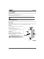
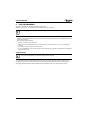
1
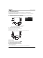
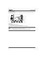
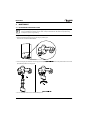
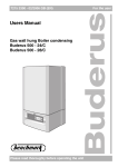
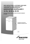
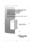
USER INSTRUCTIONS
WALL HUNG RSF GAS FIRED CONDENSING COMBINATION BOILER
GREENSTAR CDi CLASSIC
FOR SEALED CENTRAL HEATING SYSTEMS AND MAINS FED DOMESTIC HOT WATER
The appliances are for use with:
Natural Gas or L.P.G. (Catt II type C13 & C33)
Natural Gas: 29CDi GC number 47-406-34
34CDi GC number 47-406-36
38CDi GC number 47-406-38
42CDi GC number 47-406-10
L.P.G.: 29CDi GC number 47-406-35
34CDi GC number 47-406-37
38CDi GC number 47-406-39
42CDi GC number 47-406-11
6 720 803 600 (2012/06)
UK/IE
PREFACE
PREFACE
PLEASE READ THESE INSTRUCTIONS CAREFULLY
These instructions are applicable to the Worcester, Bosch Group boiler model stated on the front cover only.
These instructions apply in the UK/IE only and must be followed except for any statutory obligation.
After installation please leave this User Instruction manual and the Installation, Commissioning and Servicing Instructions with the
user.
DEDICATED TO HEATING COMFORT
Thank you for purchasing a Greenstar gas-fired condensing combination boiler manufactured by Worcester, Bosch Group. The
company prides itself on manufacturing boilers to the strictest quality control standards throughout every stage of production.
Worcester, Bosch Group has led the field in innovative boiler design and performance for almost 50 years. This heritage means all
our products are of exceptional quality and proven reliability.
The Greenstar range in particular is extremely energy efficient, offering you economical running costs and value for money. It sits in
SEDBUK Band A, and is therefore amongst the top energy rated boilers available.
There is also the reassurance of our no-nonsense 2 years parts and labour guarantee - backed up by Worcester Total Cover, an
optional complete maintenance scheme to keep your boiler operating at peak condition and efficiency.
TABLE OF CONTENTS
1
Symbols and safety precautions . . . . . . . . . . . . . . . . . 4
1.1 Explanation of symbols . . . . . . . . . . . . . . . . . . . . . 4
1.2 Safety precautions . . . . . . . . . . . . . . . . . . . . . . . . 5
2
General Information . . . . . . . . . . . . . . . . . . . . . . . . . . . 6
3
Operating the boiler . . . . . . . . . . . . . . . . . . . . . . . . . . . 7
3.1 Controls . . . . . . . . . . . . . . . . . . . . . . . . . . . . . . . . . 7
3.2 Switching the boiler on/off . . . . . . . . . . . . . . . . . . 8
3.3 Setting the central heating temperature . . . . . . . 9
3.3.1Controlling the central heating . . . . . . . . . . . . . . . 9
3.4 Setting the domestic hot water temperature . . . 10
3.5 Frost protection (for the boiler) . . . . . . . . . . . . . 11
3.5.1Frost protection (for the heating system) . . . . . 11
3.6 Domestic hot water pre-heat . . . . . . . . . . . . . . . 12
3.7 Holiday setting . . . . . . . . . . . . . . . . . . . . . . . . . . . 12
3.8 Fault condition . . . . . . . . . . . . . . . . . . . . . . . . . . . 13
4
Maintenance . . . . . . . . . . . . . . . . . . . . . . . . . . . . . . . .
4.1 Re-Pressuring the heating system . . . . . . . . . . .
4.2 Fault finding . . . . . . . . . . . . . . . . . . . . . . . . . . . . .
4.3 Error codes . . . . . . . . . . . . . . . . . . . . . . . . . . . . .
4.4 Extreme cold weather . . . . . . . . . . . . . . . . . . . . .
5
General notes . . . . . . . . . . . . . . . . . . . . . . . . . . . . . . . . 19
6
Fault or Breakdown . . . . . . . . . . . . . . . . . . . . . . . . . . . 20
7
Tips on energy saving . . . . . . . . . . . . . . . . . . . . . . . . . 21
8
Your guarantee . . . . . . . . . . . . . . . . . . . . . . . . . . . . . . 22
9
Glossary . . . . . . . . . . . . . . . . . . . . . . . . . . . . . . . . . . . . 23
2
14
14
16
17
18
6 720 803 600 (2012/06)
SYMBOLS AND SAFETY PRECAUTIONS
1
SYMBOLS AND SAFETY PRECAUTIONS
1.1 EXPLANATION OF SYMBOLS
WARNING SYMBOLS
Safety instructions in this document are framed and identified by a
warning triangle which is printed on a grey background.
Signal words indicate the seriousness of the hazard in terms of the consequences of not following the safety instructions.
• NOTICE indicates possible damage to property or equipment, but where there is no risk of personal injury.
• CAUTION indicates possible personal injury.
• WARNING indicates possible severe personal injury.
IMPORTANT INFORMATION
Notes contain important information in cases where there is no risk of
personal injury or material losses and are identified by the symbol shown on the left. They are bordered by
horizontal lines above and below the text.
ADDITIONAL SYMBOLS
Symbol
Meaning
1.
a numbered step in an action sequence
B
a step in an action sequence
1
a reference number to identify or refer to a part or item
a list entry
•
–
a list entry (second level)
Table 1 Symbols
1.2 SAFETY PRECAUTIONS
IF YOU SMELL GAS!
• Call the National Gas Emergency Service on: 0800 111 999
• Extinguish any naked flames
• Do not smoke or strike matches
• Do not turn electrical switches on or off
• Open doors and windows
• Keep people away from the affected area
• Turn off the gas control valve at the meter
BOILER OPERATION:
This boiler must only be operated by a responsible adult who has been instructed in, understands and is aware of the boiler's
operating conditions and effects.
COMBUSTIBLE AND CORROSIVE MATERIALS:
Chemically aggressive substances can corrode the boiler and invalidate any guarantee.
• Do not store or use any combustible materials (paper, thinners, paints, propellants, cleaning agents etc.) inside or within the
vicinity of the appliance.
6 720 803 600 (2012/06)
3
GENERAL INFORMATION
FITTINGS AND MODIFICATIONS:
Only a competent engineer can remove the boiler case and carry out any work, in accordance with the Gas Safety (Installation and
Use) Regulations.
• Do not remove the boiler case.
Any misuse or unauthorised modifications to the boiler, flue or associated accessories and heating system will invalidate the
guarantee.
• Do not modify the boiler or flue system in any way.
Worcester, Bosch Group accepts no liability arising from any such actions. This does not affect your statutory rights.
2
GENERAL INFORMATION
SERVICING
Ensure that the service engineer completes the Service Record in the Benchmark Checklist after each service. The
Benchmark Checklist and service interval record can be found at the rear of the Installation, Commissioning and
Servicing Instructions.
• The boiler must be serviced regularly by a competent, qualified person, such as a Worcester service engineer or other Gas Safe
registered engineer.
• Always use original spares, to help maintain the efficiency, safety and reliability of the boiler and have the Service Record
completed in the Benchmark Checklist.
The completed Benchmark Checklist will be required in the event of any guarantee work and may be required by the local Building
Control Inspector.
BENCHMARK STANDARD
The Benchmark initiative is a code of practice to encourage the correct installation, commissioning
and servicing of domestic central heating boilers and system equipment.
A “checklist” is dispatched with every boiler. This is a vital document that needs to be completed
by the installer at the time of installation. It confirms that the boiler has been installed and
commissioned according to the manufacturer's instructions.
The log book provides space for the recording of regular servicing of the boiler/heating system and this can become a valuable
document when, for example, you wish to sell the property. The log book will show a potential purchaser that the heating system
has received regular professional maintenance and servicing during its lifetime.
The Benchmark initiative aims to:
• Raise standards among professional installers
• Build and maintain high safety standards in the industry
• Improve customer satisfaction levels
• Make a contribution to the nation's commitment to climate change
4
6 720 803 600 (2012/06)
OPERATING THE BOILER
3
OPERATING THE BOILER
3.1 CONTROLS
B
A
C
2
1
L
0
3
bar
reset
eco
K
3
2
J
1
4
3
5
4
D
E
F
4
e
2
6
1
6
max
min
max
G
H
I
M
6720647361-71.1Wo
[A]
MAIN POWER ON/OFF BUTTON
[B]
COVER OR POSITION FOR OPTIONAL PLUG-IN CONTROLLER
[C]
DISPLAY
[D]
SYSTEM PRESSURE GAUGE
[E]
RESET BUTTON
[F]
ECO BUTTON (DOMESTIC HOT WATER PRE-HEAT ON/OFF)
[G]
HOLIDAY BUTTON
[H]
DOMESTIC HOT WATER TEMPERATURE CONTROL
[I]
CENTRAL HEATING TEMPERATURE CONTROL
[J]
SERVICE ENGINEER BUTTON ONLY
[K]
SERVICE ENGINEER BUTTON ONLY
[L]
BURNER INDICATOR LIGHT
[M]
POWER INDICATOR & FAULT INDICATOR (BLUE)
6 720 803 600 (2012/06)
5
OPERATING THE BOILER
3.2 SWITCHING THE BOILER ON/OFF
Switching on
B Switch on the boiler by pressing the main power button.
The power button light shows blue.
reset
3
2
1
3
4
4
e
2
5
1
6
6 720 614 059-20.1Wo
eco
6
max
max
The boiler runs for 15 minutes at minimum heating
output to fill the condensate trap. The display alternates between
and the central heating flow temperature. This occurs every time the
mains supply has been
interrupted.
Switching off
B Switch off the boiler by pressing the main power button.
The blue power button light goes out.
3.3 SETTING THE CENTRAL HEATING TEMPERATURE
B Turn the central heating temperature control to the desired level, between approx. 35°C and 90°C.
B When the burner is lit, the green indicator light underneath the
on/off switch is illuminated.
3
2
1
3
4
2
5
Position
Central heating
temperature
1
approx. 35°C
reset
2
approx. 43°C
eco
3
approx. 50°C
4
approx. 60°C
5
approx. 67°C
6
approx. 75°C
max
approx. 90°C
4
e
6
1
6
max
min
max
6 720 614 059-02.1Wo
Table 2 Settings for the central heating temperature
6
6 720 803 600 (2012/06)
OPERATING THE BOILER
3.3.1 CONTROLLING THE CENTRAL HEATING
Central heating systems must be controlled effectively using a programmer or timer and a room thermostat.
B For further information on how to control your central heating system please refer to the individual user guides for the
programmer or timer installed in your home.
3.4 SETTING THE DOMESTIC HOT WATER TEMPERATURE
B Turn the domestic hot water temperature control to the desired level, between approximately 40°Cand 60°C.
reset
eco
3
4
1
min
approx. 40°C
e
approx. 50°C
max
approx. 60°C
e
1
6
Domestic hot water
temperature
4
3
2
5
2
Position
6
max
max
6 720 614 059-03.1Wo
Table 3 Settings for the domestic hot water temperature
3.5 FROST PROTECTION (FOR THE BOILER)
Activating frost protection will turn off the central heating system.
Heating of domestic water will stay activated.
If the temperature within the boiler drops to 5°C the boiler will fire to avoid the possibility of freezing.
reset
eco
3
2
1
3
5
4
e
2
6
1
6
max
min
max
6 720 614 059-04.1Wo
To activate frost protection:
B Leave master switch on.
B Turn the central heating control temperature control to
.
3.5.1 FROST PROTECTION (FOR THE HEATING SYSTEM)
If remote pipework is likely to be subject to freezing conditions:
B Ensure the installer has fitted a frost thermostat in the area to
protect the pipework from freezing.
B Ensure the installer has added a suitable anti-freeze fluid to the water in the central heating system.
6 720 803 600 (2012/06)
7
OPERATING THE BOILER
3.6 DOMESTIC HOT WATER PRE-HEAT
You can choose to run your boiler in pre-heat mode or in ECO mode. Pre-heat reduces the time taken to produce hot water at the
tap and is controlled by the ECO button. When the ECO button is illuminated, the boiler runs in ECO mode and pre-heat is not
available.
reset
3
4
3
1
4
e
2
5
2
6
1
6
max
max
To activate pre-heat mode:
B Press the ECO button until it is no longer illuminated.
6 720 614 059-06.1Wo
eco
To activate ECO mode:
B Press the ECO button until it is illuminated.
3.7 HOLIDAY SETTING
Activating the holiday setting will turn off the central heating system.
Frost protection and heating of domestic hot water will stay activated.
reset
3
2
1
4
3
2
5
6
1
max
4
e
6
max
6 720 614 059-05.1Wo
eco
To activate the holiday setting:
B Press the holiday button until it is illuminated.
To deactivate the holiday setting:
B Press the holiday button until it is no longer illuminated.
8
6 720 803 600 (2012/06)
OPERATING THE BOILER
3.8 FAULT CONDITION
In the unlikely event of a fault occuring while the boiler is in operation the reset button and the main power indicator will flash.
The display will show a fault code.
reset
3
4
2
1
3
2
5
6
max
1
4
e
6
max
6 720 614 059-07.1Wo
eco
To reset the boiler:
B Press the reset button for three seconds.
The reset button and the mains power indicator will stop flashing.
The boiler will function normally, dependent on programmer and room thermostat settings.
If the fault cannot be cleared by pressing the reset button:
B Refer to the fault finding section on page 12 of this user guide.
B Call Worcester, Bosch Group, giving a description of the fault and, if possible, the fault code from the seven
segment display. Alternatively contact other Gas Safe registered personnel for assistance.
6 720 803 600 (2012/06)
9
MAINTENANCE
4
MAINTENANCE
4.1 RE-PRESSURING THE HEATING SYSTEM
It is important to regularly check the pressure gauge on your combination boiler to keep it running efficiently. The
pressure should be at an optimum level of 1.5 bar. If the pressure falls below 1 bar the boiler may stop working
and require re-pressurising & resetting.
To re-pressurise the heating system:
1. Remove the bottom panel to gain access to the filling key and filling link.
The fillink link is situated as indicated below:
2. Insert the filling key into the bottom of the charging link and push it upwards. The arrow on the key shaft must be in line with the
open padlock symbol on the charging link.
3. Turn the filling key clockwise to the closed padlock position.
10
6 720 803 600 (2012/06)
MAINTENANCE
4. Test whether the filling key is locked properly in closed padlock position by pulling down on the key.
If the key is loose, can be rotated or pulled out of the filling link please repeat steps 1 to 3.
5. With filling key in locked position turn the water mains inlet knob (white) anticlockwise to open.
This fills the heating system with mains water.
6. When the pressure gauge reads 1.5 bar turn the white water mains inlet knob clockwise to close.
7. Turn the filling key anticlockwise to the open padlock position and remove from the charging link.
8. Stow the filling key back inside the bottom panel underneath the boiler.
6 720 803 600 (2012/06)
11
MAINTENANCE
4.2 FAULT FINDING
This table gives information on basic operating system problems.
Problem
Cause
Remedy
EA fault code flashing on
display
No gas supply/low gas supply pressure
B Contact your gas supplier.
Condensate outlet blocked
B If it is safe to do so, check your condensate pipe
outlet for blockages, such as ice or foreign
objects.
Flue blocked
B If it is safe to do so, check your flue outlet for
damage or blockages.
Thermostatic radiator valve(s) set too
low
B Increase thermostatic radiator valve setting(s)
Temperature control for central heating
flow on boiler set too low
B Increase central heating flow temperature control
setting
Air trapped in heating system
B Bleed radiators and recharge heating system
Low system water pressure
B Re-pressurise the system, refer to pages 10
Low temperature setting on the boiler
controls
B Increase settings on boiler controls
Desired room temperature is
not reached
Desired room temperature too Radiators are too hot
high
B Turn down thermostatic radiator valves/room
thermostat
B Reduce central heating temperature by turning
down the Central Heating control on boiler
Heating stays on for too long
Clock is incorrectly set
B Check setting and adjust
ON/OFF Indicator is not
illuminated
Momentary power failure
B Disconnect boiler supply, wait a few seconds then
reconnect.
Hot water temperature too low Temperature set too low on boiler
controls
B Check setting and adjust
Water flow at tap too high
B Reduce flow rate at tap
Air trapped in heating system
B Bleed radiators and recharge heating system
Low system water pressure
B Re-pressurise the system, refer to pages 10
Hot water temperature too high Temperature set too high on boiler
controls
Water flow at tap too low
B Check setting and adjust
B Increase flow rate at tap
Table 4 Fault finding
12
6 720 803 600 (2012/06)
MAINTENANCE
4.3 ERROR CODES
When calling Worcester, Bosch Group, you may be asked for the error code. This Table is for you to help identify
the possible cause of the fault.
B Do not try to rectify any of the faults listed below by yourself.
B Contact British Gas or a competent, qualified engineer
(Gas Safe registered personnel).
Error code
Description
A7
Hot water NTC sensor defective.
A8
Break in communication to TD200 or/and DT10
b1
Code plug not detected.
C6
Fan speed too low.
E2
CH flow NTC sensor defective.
E9
Safety temp. limiter in CH flow has tripped.
EA
Flame not detected.
Check, if it safe to do so:
• is gas is on in the house
• for frozen condensate pipe
• for blocked flue outlet
F0
Internal error.
F7
Flame detected even though boiler switched off.
FA
Flame detected after gas shut off.
Fd
Reset button pressed by mistake.
6 720 803 600 (2012/06)
13
MAINTENANCE
4.4 EXTREME COLD WEATHER
In some instances where the condensate pipe work is run externally or in an unheated area, such as a garage, the condensate pipe
work can be at risk of freezing, even if well insulated.
A frozen/blocked condensate pipe will cause the boiler to shut down.
WARNING: Falling hazard!
Failure to follow this guidance may result in personal injury.
B Only attempt to thaw a condense pipe that is at ground level, and that is easily accessible.
B Never attempt to thaw a condense pipe that is at height.
CAUTION: Pipe damage
B DO NOT use boiling water to thaw the condensate pipe!
If the condensate pipe has frozen:
B Locate the blockage.
It is likely that the pipe is frozen at the most exposed point outside the building or where there is an obstruction to flow.
This could be the open end of the pipe, at a bend or elbow, or where there is a sag in the pipe in which condensate can collect.
The location of the blockage should be identified as closely as possible before taking further action.
B Thaw the frozen pipe.
The pipe can be thawed by applying a hot water bottle, a microwaveable heating pack (the sort used for muscular aches and
pains) or a cloth soaked in hot water to the exterior of the pipe, close to the point of blockage.
Hot water, but not boiling, can also be poured onto the pipe from a watering can or similar container.
B Once the pipe has been thawed the boiler must be reset, press the reset button for five seconds and wait two to three minutes
for the boiler to restart.
B If the boiler does not restart, contact Worcester, Bosch Group Appointments Team on:
0844 892 3000.
B Contact your installer in order to find a permanent solution to the problem.
14
6 720 803 600 (2012/06)
GENERAL NOTES
5
GENERAL NOTES
SEALED HEATING SYSTEMS
This boiler is fitted to a sealed heating system which is pre-pressurised. The optimum level for system pressure on a Greenstar CDi
Combination boiler is 1.5 bar indicated on the pressure gauge.
B Check regularly that the pressure is maintained.
B Contact your installer or maintenace engineer if a permanent significant drop is indicated on the pressure gauge.
For information on how to “Re-pressurise the heating system” refer to page 10.
PLUMING AND CONDENSATE DRAIN
This is a condensing boiler and the flue terminal will, at times give out a plume of water vapour. This is quite normal.
The boiler also produces quantities of condensate which is discharged regularly via a pipe to drain. This pipe must not be blocked
or altered in any way.
PUMP ANTI-SEIZURE
If there has been no heating demand for 24 hours the boiler will run the system pump for a few seconds to reduce the possibility of
pump seizure during long periods of inactivity. This is usually more frequent during the summer months.
CLEARANCES
Your installer will have provided adequate space around the boiler for
safety and servicing access.
*600 mm service clearance required to a fixed surface
(**20 mm from removable door or panel)
B Do not restrict this space with the addition of cubpoards, shelves
etc. around or next to the boiler.
VENTILATION
This is a room sealed boiler and does not require any air for
combustion from inside the property. If a compartment is built
around the boiler after installation, then this must be carried out as
described in the Installation Manual.
CAUTION: Risk of damage to the boiler.
B Do not operate the boiler if the flue terminal is
obstructed or damaged in any way.
6 720 803 600 (2012/06)
15
FAULT OR BREAKDOWN
6
FAULT OR BREAKDOWN
This boiler is supported in the UK and Eire by Worcester, Bosch Group.
Specialist Service Engineers are available to attend a breakdown occurring on this boiler.
Invoices for attendance and repair work carried out on this boiler by any third party will not be accepted.
• No charge will be made for parts and/or labour providing:
A boiler fault is found and the boiler is within the guarantee period. Reasonable evidence of this must be supplied on request. i.e.
the Benchmark Checklist.
• A call-out charge will be made where:
– The boiler is outside the guarantee period.
– Evidence cannot be provided that the first year service inspection has been carried out (i.e. an entry in the Benchmark
Checklist).
– Our Field Service Engineer finds no fault with the boiler.
– The cause of breakdown is misuse or with other parts of your plumbing/heating system, or with equipment not supplied by
Worcester, Bosch Group.
TECHNICAL SUPPORT
No boiler fault is found on over 30% of all service calls.
In the case of a suspected fault, refer to the fault finding section of this guide.
In the event of a boiler fault or breakdown please contact Worcester, Bosch Group appointments team on 0844 892 3000.
Your advisor will arrange for an engineer to call with the minimum of delay; under normal circumstances this will be from 1 - 3
working days (excluding weekends and bank holidays) for priority breakdown situations (no hot water and/or heating).
16
6 720 803 600 (2012/06)
TIPS ON ENERGY SAVING
7
TIPS ON ENERGY SAVING
HEATING ECONOMICALLY
The boiler is designed to provide a level of comfort while keeping gas consumption and the resulting environmental effect as low as
possible. The gas supply to the burner is controlled according to the level of demand for heat. The boiler continues to operate with
a low flame if the demand of heat reduces. The technical term for this is modulating control. Modulating control reduces
temperature
fluctuations and provides even distribution of heat throughout the home. This means that the boiler may stay on for relatively long
periods but will use less gas than a boiler that continually switches on and off.
NEW CONTROL SYSTEMS
Upgrade your heating control system if necessary with the latest equipment available. The minimum level of control is a
programmer, interlocking room thermostat and thermostatic radiator valves.
CENTRAL HEATING SYSTEMS WITH ROOM THERMOSTATS AND THERMOSTATIC RADIATOR VALVES
The central heating control on the boiler should be set to maximum rated temperature of the central heating system. The
temperature of each room can be set individually (except room with the room
thermostat) using the thermostatic radiator valves. If damaged, replace the plastic tops used to adjust the thermostatic radiator
valve. It is also advisable to manually adjust all thermostatic radiator valves every 2-3 weeks to prevent them sticking.
ROOM THERMOSTATS
Reducing the setting of the room thermostat by 1°C can reduce fuel consumption by up to 10 %.
ROOF INSULATION
Around 30 % of the heat loss from a property is through the roof. Replace any old insulation with new insulation, preferably of
around 200 mm thickness or more.
WINDOW FRAMES
Single glazed windows, particularly those with steel frames, can loose a great deal of heat. Consideration should be given to
replacement with PVCu or wooden framed double glazing units.
CURTAINS
Lined curtains, or heavier full length curtains can provide excellent insulation. However, always ensure that the curtains do not
drape over radiators.
DRAUGHTS
To ensure that draughts around doors, windows, letterboxes and keyholes etc. are reduced by using a suitable draught excluder.
RADIATORS
Often radiators are sited underneath a window. The performance of the radiator will be affected if curtains are allowed to drape over
radiator or shelves are fitted above it.
The temperature obtainable in any given room is dependent on all radiators being operated at the same time. If you decide to turn
off radiators in unused rooms, spare bedrooms etc., you may experience slightly lower room temperatures in rooms adjacent to
unheated rooms.
6 720 803 600 (2012/06)
17
YOUR GUARANTEE
8
YOUR GUARANTEE
This boiler has a guarantee against faulty materials or workmanship for a period of two years from the date of installation subject to
the following terms and conditions:
• During the period of this guarantee any components of the boiler which are proven to be faulty or defective in manufacture will
be exchanged or repaired free of charge by Bosch Thermotechnology Ltd.
• The householder may be asked to prove the date of installation, that the boiler was correctly commissioned and, where
appropriate, the first year's service has been carried out to the satisfaction of Bosch Thermotechnology Ltd., when requested.
These should be documented as a part of the Benchmark Checklist.
• The boiler has been used only for the normal domestic purposes for which it was designed.
This guarantee does not affect your statutory rights.
GUARANTEE REGISTRATION
Your Greenstar boiler carries a two year guarantee against faulty material or manufacture subject to Terms and Conditions.
To read the full Terms & Conditions please visit us on-line at www.worcester-bosch.co.uk/guarantee. The Guarantee Registration
form is available on this same page and can be completed and submitted electronically.
Alternatively please telephone one of our Guarantee Registration advisors on 0844 892 2552.
Your statutory rights are not affected by the manufacturers guarantee.
FOR YOUR OWN RECORD:
Please ensure that the Benchmark Checklist has been completed by your installer or service engineer.
Model
Serial No.1)
Type/size
Date of installation
Name of Installer
Telephone number of Installer
Table 5
1) See boiler identification label on boiler fascia or Benchmark Checklist in the back of the Installation, Commissioning & Servicing
Instructions.
18
6 720 803 600 (2012/06)
GLOSSARY
9
GLOSSARY
Central heating systems
All radiators must be heated at an even rate. If the top of a radiator is at a lower temperature than the bottom then it should be bled
by releasing air through the bleed screw at the top of the radiator.
Ask your installer to show you how this is done.
This boiler is fitted to a sealed system. Should water leaks be found or if excessive bleeding is required, then a service engineer must
be contacted to inspect the installation and rectify any fault.
Only additives that are compatible with aluminium may be used in the system. Any incompatible additive used will invalidate the
guarantee.
Pluming and Condensate drain
This is a condensing boiler and the flue terminal will, at times give out a plume of water vapour. This is quite normal.
The boiler produces condensate which is discharged regularly by a syphon within the boiler via a plastic pipe to a drain. This pipe
must not be blocked or altered in any way.
Room thermostat / programmer
A room thermostat / programmer must be fitted to control the central heating. This controls the times and temperatures of the
central heating, preventing the boiler from firing unnecessarily. Refer to the instructions supplied with the thermostat and
programmer for further information.
Thermostatic radiator valves
Thermostatic radiator valves must be fitted in sleeping accommodation. It is recommended that this type of valve is fitted to all but
one of the radiators. The remaining radiator, where the room thermostat is located, must be uncontrolled and left open.
Pump over run function
After the boiler has finished a demand for central heating or hot water, the pump may continue to run for a short while to dissipate
the heat from within the boiler.
Pump anti-seizure
If there has been no heating demand for 24 hours the boiler will run the system pump for a few seconds to reduce the possibility of
pump seizure during long periods of inactivity.
SEDBUK
Seasonal Efficiency of Domestic Boilers in the UK.
6 720 803 600 (2012/06)
19
WORCESTER, BOSCH GROUP:
TECHNICAL SUPPORT: 0844 892 3366
APPOINTMENTS:
SPARES:
LITERATURE:
Worcester, Bosch Group
Cotswold Way, Warndon, Worcester WR4 9SW.
Tel. 0844 892 9900
Worcester, Bosch Group is a brand name of
Bosch Thermotechnology Ltd.
worcester-bosch.co.uk
6 720 803 600 (2012/06)
0844 892 3000
01905 752571
0844 892 9800
TRAINING:
01905 752526
SALES:
01905 752640