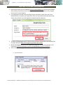
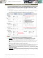
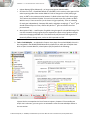
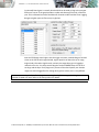
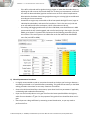
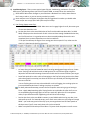
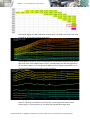
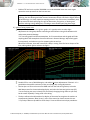
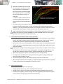
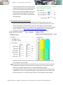
1
An intermediate guide to operation of the latest CROME engine tuning and ROM editing software © 2011 GravityLabs, Inc. CROME (Cui’s ROM Editor) v1.6.2 User Manual revision 2.0 March 10, 2012 by Miles David CHAPTER 1. REQUIREMENTS Please visit www.TuneWithCROME.com to download the latest CROME software and read this manual thoroughly for proper operation. 1 GHz processor, 512 MB RAM, 5 MB hard disk memory Windows XP Service Pack 2 or newer Microsoft-based operating system Honda OBD1 EPROM modified ECU with the J12 internal jumper removed One of the following EPROM burning or emulating devices: - Moates Burn1 or Burn2, Xtronics Pocket Programmer, Willem PCB3 or newer - Moates Ostrich or Ostrich 2.0 emulator, Xtronics ROMulator One of the following datalog header connections: - Moates Hondalog or Xtreme Hulog adapter, or Nokia DKU-5 USB adapter Any available wideband O2 sensor controller A purchased CROME license and registration string is necessary for the purposes of this manual, as the advanced tuning section focuses primarily on the Gold ROM platform. INDUSTRY PREFERRED APPLICATIONS Although not required, CROME Gold files cannot be accessed without a Pro license, and cannot be saved or burned to an EPROM chip without a Dealer license. Keeping this in mind, the following options are provided based on common known-working combinations used in the tuning industry: 1. CROME Pro (single-use) License ($149) with Moates Ostrich emulator ($175) 2. CROME Dealer License ($450) with Moates Ostrich or Burn2 ($85) 3. Unfortunately the Moates Demon RTP unit should not be considered for use with CROME 1.6.2 as it is known to have connection issues with most laptops. Some tuners are able to make this combination work, and theoretically it is ideal, however the success rate is negligible. - Hulog/HondaLog USB adapter - AEM UEGO, Innovate LC-1, or PLX wideband O2 sensor controller - Windows XP laptop with at least 2 USB ports, 1GB RAM - Tip: HP laptops get very hot, which can be uncomfortable for tuning. It is not recommended to use an HP laptop to operate CROME © 2011 GravityLabs, Inc. CROME (Cui’s ROM Editor) v1.6.2 User Manual revision 2.0 March 10, 2012 by Miles David CHAPTER 2. SETUP AND CONFIGURATION 1. Download the latest version of CROME at www.tunewithCROME.com and opt to open CROME after installing; the welcome screen should give an option to select [Register]. If not, navigate the menu bar to Help » Register. 2. In the Registration window, select [Get Reg String] at the bottom, which directs you to the CROME website to complete your registration. Once you’ve purchased and acquired your Reg String, copy and paste it into the Registration window and select [Register]. 3. The Nokia USB Datalogging setup is rather involved, and users should refer to the following URL for proper directions: http://forum.pgmfi.org/viewtopic.php?t=1663 4. Moates Datalogging cable drivers are supported through FTDI, and the latest package can be found here: http://www.ftdichip.com/Drivers/CDM/CDM20814_WHQL_Certified.zip 5. After installing drivers, right-click on My Computer and select Properties from the menu a. For XP machines: © 2011 GravityLabs, Inc. CROME (Cui’s ROM Editor) v1.6.2 User Manual revision 2.0 March 10, 2012 by Miles David b. For Vista/ Windows 7 machines: 6.) While in the Device Manager, locate and expand the Ports (COM & LPT) tree and plug in the datalogger USB. The device should appear under the tree as USB Serial Port (COM___). Doubleclick the port to open Properties. Change the Bits per second (aka baud rate) to 38400, select [OK] and keep the Device Manager open. © 2011 GravityLabs, Inc. CROME (Cui’s ROM Editor) v1.6.2 User Manual revision 2.0 March 10, 2012 by Miles David 7.) Open CROME, and navigate the menu bar to File » Settings or click on the Settings icon in the toolbar. Select the Tuner Comm tab and set Serial Protocol to Crome QD3 or QD2, unless you’re using an older ROM/firmware version. Make sure the Port number and Baud (Bits per second) matches the Device Manager profile, as shown below: 8. Move to the Real Time Programming tab, if equipped with a Moates, Xtronics, or PGMFI product (Willem and other EPROM burners use external software to program ROM files). Connect the EPROM burner first, and observe which port is designated for it in the Device Manager. If you are only equipped with an emulator or Moates Demon RTP, treat it as your chip burner for this step: (continued) © 2011 GravityLabs, Inc. CROME (Cui’s ROM Editor) v1.6.2 User Manual revision 2.0 March 10, 2012 by Miles David 8.5 (continued) Select the proper hardware and port (COM number will be black if it’s available). The Baud rate for most RTP and Burn hardware is 920000; however Xtronics Baud rate is usually 115200. Open the properties of the associated port in the Windows Device Manager and change the Bits Per Second to 920000 (or closest given value, may be shown slightly higher). 1. Even if using the Ostrich or ROMulator, select the tick box Used for 27SF512 unless you are specifically using an obsolete 27SF256 chip with a Moates or Xtronics chip burner. 9. If you are using a chip burner and emulator by the same company (i.e. Pocket Programmer and ROMulator, or Burn2 and Ostrich 2) unplug your chip burner and observe the new port number in Device Manager while connecting the emulator. Otherwise, skip this step. If you are using a chip burner and an emulator by different manufacturers, refer to step 8 and set up the second device using a unique port number. Again, available ports are shown in black under the port list in CROME settings. Double-click the properties for the port, select the Port Settings tab and click the [Advanced…] button. At the bottom, change the port number to the same port that was designated for the chip burner – this allows the user to swap devices without having to constantly change the port settings in CROME: * This is the same process used by GravityLabs to configure personal and commercial laptops. If these procedures do not work, refer to the troubleshooting section of this manual or www.PGMFI.org for more technical information on this process. © 2011 GravityLabs, Inc. CROME (Cui’s ROM Editor) v1.6.2 User Manual revision 2.0 March 10, 2012 by Miles David CHAPTER 3. BASIC ROM EDITING For the purpose of this manual, many fundamental and integral elements of ECU theory and tuning have been omitted, as this manual focuses primarily on the functionality of the CROME program. Please visit www.PGMFI.org for in-depth technical details and full explanations on the nature of this program. Examining basic features: a. Tables (F2) – these reference the MAP sensor to detect load, and the Engine Speed (RPM) sensor to find a value the ECU will can calculate to log data and send signals. Two of the tables are used constantly to run the motor: Fuel, and Ignition Timing (F5/F7) The secondary tables (F6/F8) are used for Vtec/nitrous/methanol/etc. to control fuel and timing under different conditions that are not consistent and require an output to be engaged. This will be explained more later on. Duty cycle determines if your injectors can handle the application’s power requirements, and can also explain fuel cut. If the duty cycle of your basemap (which should always be richer than necessary) exceeds 80%, invest in larger fuel injectors and/or other fuel system components to increase flow and reduce the pulse duration. © 2011 GravityLabs, Inc. CROME (Cui’s ROM Editor) v1.6.2 User Manual revision 2.0 March 10, 2012 by Miles David Ignition tables (F5/F6) are relatively consistent, with the general rule of thumb that the more torque (larger fuel value) in any given cell, the mixture will reach peak combustion faster, needing less timing advance. It is strongly advised to have a full understanding of combustion and detonation (engine knock) before modifying this region. b. Graphs (F3) – Useful for observing tables in a more fluid form to estimate peak torque, cross-reference fuel and timing relationships, and easily identify any kinks or glitches in tables that may cause erratic performance. More detail will follow in later chapters. Graphs are essentially turned 90° counterclockwise from the tables, although timing lines will appear inverted since ignition values usually decrease as fuel increases; with graphs, MAP lines move independently rather than fixed like columns. © 2011 GravityLabs, Inc. CROME (Cui’s ROM Editor) v1.6.2 User Manual revision 2.0 March 10, 2012 by Miles David CHAPTER 4. PLUGINS AND ROM OPTIONS (F4) For non-Gold files (other than P13) only the supported P30 ROM will be used for demonstration. Before continuing with any P30 based file options, select Plugins » Enhancements » Remove Checksum Routine. This tells the ECU to ignore errors when files contain more information than the stock program. 1. Select Plugins » Enhancements » Add Extra Features to install more controls to the Options menu. These are basic desirable features for Honda tuning. Select Options (F4) 2. 3. 4. 5. In order by section, here is the relevant detail for each function: Rev Limiter – applies to the secondary tables if VTEC is enabled. The fuel is cut at the specified value and is restored at the RPM value specified in the Settings window. Idle – controls the IACV (Idle Air Control Valve) which allows air to pass around the throttle body. This should only be adjusted if the engine dies during deceleration or when idling, especially with aggressive cams or individual throttle bodies. VTEC – dictates when the VTEC solenoid is activated and the secondary tables are used. IAB is only enabled with the P72 and P13 ROM specifically for use with P72 and P13 ECUs in conjunction with either the B18C1 GSR motor or the H22A motor. Tuning this feature will be covered in later chapters. Speed Limiter – uses fuel cut to limit speed in the same manner as rev limiting. This can be a beneficial feature for emissions or security when using dual chips. © 2011 GravityLabs, Inc. CROME (Cui’s ROM Editor) v1.6.2 User Manual revision 2.0 March 10, 2012 by Miles David 6. Launch Control – sets a rev limiter that is only active between 0-8mph to assist in smooth launching and building boost with turbo applications. It can only be perfected through tuning trial. 7. Full Throttle Shift – engages a rev limit at 100% throttle while the clutch is depressed to revmatch the engine for the next gear to save time over heel-and-toe shifting. At redline, determine at what RPM the next gear picks up and set the value. See Attachment #2 for help. Be advised this feature in standard ROMs only works if the clutch button is wired to the A/C circuit pin B5 on the ECU. If the FTS rev limiter is always engaged, see troubleshooting. 8. Shift Light – provides a reminder to upshift that’s sent to the Check Engine Light in the dash cluster when nearing the end of peak power. Depending on gearing/ speed and reflex, this may need to be set lower than the actual peak power range. 9. Boost Limit – provides a fuel cut for boost protection over a certain value. Usually used to identify the ROM or MAP sensor’s highest threshold before the values exceed measurable limits. This is NOT to be used as an alternative to a wastegate to stabilize boost. 10. Sensors – many applications and/or ECUs do not have all available sensors that the P30 offers, so disabling (unchecking) those removes the Check Engine Light & resulting trouble code and removes the input data from the ECU’s calculations. Especially for tuning, it is ideal to remove variables such as the O2 which skews wideband readings, the Barometer which skews the MAP sensor, and the ELD which shifts the injector pulse offset. Other selections in the Plugins » Enhancements tree include: 11. 12. 13. 14. Rev Tools – Extends the RPM table range to 11,000 RPM for high-revving motors. Edit Gear Correction – obsolete, can now be changed in Advanced Tables. Edit Gear Table – same as above, designed by a different author. Step Ignition Retard – applies reduced timing to specific ranges of boost to the tables. The default settings are good for most mid-power applications, however for hotter-running or less-efficient boost setups the values should be reduced more rapidly. This is an advanced tuner function that should be practiced with extreme caution without experience. 15. P30 Option Byte Hack – if options are not working properly or the ROM is causing a solid CEL 16. Quick Datalogger +RTP – should be applied to every file where datalogging will be used. Without this plugin, the ECU does not translate data correctly to be deciphered by CROME. 17. VTP+VTS Remover – use with caution; if the engine does not have a VTP or the VTP/VTS is acting improperly, it can be disabled here. The VTP return wire needs to be grounded out. 18. Plugins » Utilities » Calibrate Non-Honda TPS – Works with the P30 ROM to adjust a TPS that has 0% and 100% throttle values different from the 0.5v and 4.5v norms. This is a common utility and often solves several troubleshooting concerns. It can tuned by either reading direct voltages, or datalogging open & closed throttle (with the key on & engine off), and adjusting the plugin values until readings show ≤0% and ≥100% © 2011 GravityLabs, Inc. CROME (Cui’s ROM Editor) v1.6.2 User Manual revision 2.0 March 10, 2012 by Miles David Selections in the Plugins » Control tree include: 19. Advance Idle – useful for bogging and dying when decelerating or with aggressive cams. Most performance motors will need higher idle resume, although there is no generic profile. Cams and applications with heavy fuel flow that don’t operate well under leaner conditions or low RPM will often try to rev even during idle, so idle cut values may need reduction if surging is too extreme. 20. ABT+ Map Cutoff – seemingly for older engines using a “missing link” hack on a stock MAP sensor. There is no modern application where this unit is used, as it has been deemed too dangerous and unreliable. 21. ABT+ Close Loop MAX Load Edit – adjust what the highest MAP value the ECU will use the O2 for adjusting AFR to 14:1 (P30 ROMs do not reference the Lambda table to adjust fuel). 22. Advanced VTEC Setup – allows user to set specific VTEC points depending on engine load. Useful for road racers, although only accurately tunable on a load-bearing dyno. Only experienced professionals with intimate knowledge of VTEC functionality should attempt tuning this. 23. Air Conditioning Cutoff – by setting an RPM and TPS maximum, the A/C turns clutch disconnects and the ECU stops compensating for the A/C unit above the specified level. A good option for daily drivers as well as programming custom outputs. Selections in the Plugins » Misc tree include: 24. Disable/Enable IACV – engines controlled strictly by the butterfly screw, ECUs with inoperable IACV circuits, and ITB setups benefit from this feature. 25. Select X Tranny – used for per-gear datalogging, per-gear fuel trim and custom controls. © 2011 GravityLabs, Inc. CROME (Cui’s ROM Editor) v1.6.2 User Manual revision 2.0 March 10, 2012 by Miles David Primary Plugins require thorough understanding, and are as follows: i. Advanced BoostTools+ This tool adds additional MAP columns for boost ranges, skews the columns for aftermarket MAP sensors, and customizes the MAP sensor voltage scale that the ECU uses to reference tables. Navigate the menu bar to Plugins » Advanced BoostTools+ and select the MAP sensor you’re currently using. 19. If your sensor is not shown, obtain the manufacturer’s datasheet and manually enter the specified max and min pressures as well as your atmospheric voltage reading. Next enter the amount of boost columns you need – generally one column for every 2psi is safe, but if you notice fuel values don’t change significantly between certain columns you can eliminate them and rescale the values: The same can be done for RPM rows; just don’t change the first OR last column/row as it may corrupt the ROM. Always be sure to save a new ROM instance before any significant changes. You may notice the boost area is grayed out, this is normal. Toggle-On the Tuner (CTRL+T) if the tuner bar is not at the bottom, highlight the cells, and click the Toggle Selected Cell icon: ii. FuelTools This should be used after applying BoostTools or ITB Tools. This skews multipliers in the ECU related to fuel calculations and delivery. If your fuel system is modified, this is an essential tool. After installing the plugin, navigate to Tools » Fuel Multiplier (F) and enter injector and rail pressure information and/or any changes made in displacement. © 2011 GravityLabs, Inc. CROME (Cui’s ROM Editor) v1.6.2 User Manual revision 2.0 March 10, 2012 by Miles David Engine Capacity (displacement) can also be helpful for calculating fuel for new compression ratios as a percentage difference: multiply your existing compression by 10 and enter it as Old Capacity. Multiply your new compression ratio by 10 and enter it as New Capacity. Next select the [Advanced] tab, note the Final Multiplier from the first page. For general purposes, O2 and tip-in should be kept at 1.00, unless working with special fuels (E85, race fuel, nitro). Cranking and Post-Startup should be slightly higher than the Final Multiplier. Finally, Offset should be gradually increased in increments of 10.00 until the idle remains steady at 14.7:1 AFR and surging ceases. This is strictly trial and error; see Injector Battery Offset before adjusting offset. Click [OK] and the multipliers will be applied to the rom. iii. ITB Tools Plus Jr 0.1 Use with extreme caution tuning ITBs with standard ROMs; it is HIGHLY recommended to use a Gold base file for tuning Alpha-N, however it can still be done proficiently with a P30 base. The remainder of ITB calibration is outlined in Chapter 8.7 Unused Plugins can be removed or rearranged in the menus by selecting Plugins » Plugin Manager and selecting individual scripts by their file name. To add or reinstall a plugin, simply click [Install New Plugin] and search the directory. © 2011 GravityLabs, Inc. CROME (Cui’s ROM Editor) v1.6.2 User Manual revision 2.0 March 10, 2012 by Miles David CHAPTER 5. TOOLS AND SETTINGS 1. Advanced Tables (L) – this tool is explained first, as it is relevant to comprehend in order for the next topics to be properly understood. This is only available on standard ROMs, but the tables are also implemented in the CROME Gold ROM. Proceed to Tools » Advanced Tables a. Closed Loop Control – focus on the CUT curve first; for the most part, the RES curve will always have slightly lower values. Determining these triggers should be based on when the O2 is no longer functional, such as any target AFRs richer than 14:1. b. IAT Fuel Compensation – cold air is denser, and needs more fuel to maintain proper mixture. This, along with most fuel and timing scales, should be datalogged thoroughly from stone-cold to heat-soaked and plotted on a graph to derive percentages. Motors can benefit from adjusting this scale for rough cold-starting or if excessive fuel fluctuations occur during warm-up. Adjustments should be made based on percent, as 1.00 = 100%, 0.94 = 94% and so on. c. ECT Fuel Compensation – the same concept from the IAT, but more involved: o Open Loop – any terms when the O2 is not compensating for fuel, or if the O2 is disabled. Tuning is reliant on IAT, so both of these values should be plotted together to determine which should be scaled more aggressively. o Max Bounds – high load at colder temps usually needs more fuel, so these values should always be higher than Open Loop. o Closed Loop – since the O2 compensates fuel on its own, this should usually stay at 1.00 (100%) unless the fuel needs at the point where system switches to closed loop are still more than 25% above normal. o Auto Tranny – if applicable, the ECU will use this table instead of any other tables, as the torque converter has a different method of distributing load. If excessive gear switching is noticed, try adding compensation. o 0016fh – this number is the hex address on the chip for where this scale is found, but so far there’s been no development on what it’s for. d. ECT Fuel Idle Compensation – really only for minor adjustments during idle, or within the Resume range of the IACV. e. Post Fuel Compensation – a simple map that the ECU uses right after starting the engine until the ECU collects enough useable information from the ECT/IAT. f. Crank Fuel Compensation – useful for ironing out cold-start issues. Start excessively lean and gradually add pulse width. Do the same for Post Fuel if the engine doesn’t stay running or hesitates/gurgles. g. Idle Speed vs. ECT – helps warm the engine during colder operation. Rarely should this ever exceed 2000 RPM. Standard cold-hot is approximately 1500-750. h. Idle Speed (moving) vs. ECT – helps protect the engine from dying and helps synchronize gears while switching from neutral to gear. Advance only if necessary. If you find it difficult to engage gears from neutral while moving, reduce these speeds. © 2011 GravityLabs, Inc. CROME (Cui’s ROM Editor) v1.6.2 User Manual revision 2.0 March 10, 2012 by Miles David i. j. k. l. m. n. o. p. q. r. Individual Cylinder Trim – sometimes used for changing the fuel multiplier without changing duty cycle when importing custom ROMs to a new file. It’s NOT recommended to do this unless you are highly experienced. Otherwise, some motors (especially B series) can run leaner in one cylinder, so this allows the ROM to compensate and prolong the life of the motor as well as increase power. VERY dangerous to modify without datalogging EGTs for each cylinder. VTEC Switchover – much like the plugin, the best way to tune this feature is on a dyno, although fuel graphs can be used as well. This is the point the ECU signals the VTEC solenoid to engage, and switches the ROM to the secondary tables. VTEC tuning is explained in later chapters. VTEC Load Threshold – divides the VTEC crossover point dependent on a MAP value. Beware that the table is backwards from the graph orientation here. If having trouble getting VTEC to switch properly, try lowering the mbar values on the lower RPM range. This feature takes practice, it’s recommended to start with values just above the O2 Closed Loop cutoff point. ECT ign Correction Retard 1 – high load ignition dampening for overheating. Only modify this if there is significant power loss/ engine knock during heat soak. ECT ign Correction Retard 2 – do not change these values. ECT ign Correction Advance 1 – high load ignition advance; colder combustion usually benefits from higher advance. Tune this as you would the ignition tables, starting from stone-cold to heat-soaked. ECT ign Correction Advance 2 – low load ignition advance, same process. Retard if IAT <#b5h – the hexadecimal translation of #b5h is 181; it is speculated this corresponds to IAT values less than 181 degrees F and accounts for common air density variations. Only in very rare situations are these numbers altered. IAT ign correction – When intake charges get too hot, ignition is retarded to avoid detonation. It’s a safety net; intake charges should never remain this hot. Injector Battery Offset (stock) – When using injectors other than stock 240cc high impedance (saturated) Honda injectors, this usually requires attention: Click the “more” dropdown to select from common injector presets. This changes the spray pattern that different injectors need to operate efficiently. Refer to Offset in the Fuel Multiplier dialogue from the previous chapter for more information. To check Ohm (impedance) use an Ohmmeter to test resistance across the injector pins. With the Honda ECU, a minimum of 10 Ohms between the injector positive lead and the ECU ground is required to operate efficiently. © 2011 GravityLabs, Inc. CROME (Cui’s ROM Editor) v1.6.2 User Manual revision 2.0 March 10, 2012 by Miles David s. Injector Battery Offset (advanced) – no longer used, do not alter this table. t. Per Gear Fuel Trim – some ROMs default at 2.00 (200%) in this section, so be aware of this when importing tables from another ROM. It’s best to change this to 1.00 (100%) right away, as 200% is the maximum value however it’s ideal to have more fuel in lower gears. This is where the Individual Cylinder Trim tool can be used to set all 4 cylinders at 200%. With this tool, it’s best to tune 4th (or the closest 1:1) gear perfectly. Then run a datalog for each gear independently. Compare AFR results, and adjust accordingly. 1st and 2nd gear should almost always run richer, and for daily drivers 5th gear can afford to be a few percent leaner. u. Base Ignition Table – a useful option for global timing changes for a broad RPM range. This can save time while tuning engines that are expected to require a lot of ignition changes, rather than changing individual cells. This should really only be used if the engine has a drastically different timing curve, such as an H22 imported to a P30. 2. Tools » Fuel Multiplier – as explained in Chapter 4 as a plugin for non-Gold ROMS, this tool is also integrated in the CROME Gold ROM under the Options tree, which we will explain here. With an open CromeAu Base file, select Options (F4) and perform the following: Injector Size has a comprehensive list of common injectors, however if the manufacturer and/or size is unknown, you can type in an estimated cc value for now and adjust offsets in the next section. © 2011 GravityLabs, Inc. CROME (Cui’s ROM Editor) v1.6.2 User Manual revision 2.0 March 10, 2012 by Miles David Offset should be kept at 0 for now unless you commonly have success with a particular value. When you change the injector size, the Final Multiplier in the bottom status window will change to reflect a percentage over what the ROM was previously set at (usually stock, otherwise the scale gets too complex). This should be used to calculate additional adjustments or the engine will not run. Be sure not to mistakenly use positive percentages for these adjustments. Keep in mind the non-Gold ROM Fuel Multiplier plugin is disabled and the Advanced Tables have been migrated and consolidated into this feature. Next, select the [Advanced Fuel Corrections] tab/button: In all the Options tables in the CromeAu base ROM, the advanced tables highlight the active cells in purple to show live data. As mentioned in the illustration, all of these cells can be changed in real-time by clicking and typing, or double-clicking, and pressing enter. Be sure to save a copy of your ROM (if Dealer edition purchased) before making changes here. Battery Offsets should automatically change if a specific injector was selected from the General Fuel Corrections page, and rarely need adjustment. Otherwise, change offset values to 100, and continue to move up in 50microsecond increments for all surrounding cells until startup fuel delivery improves. © 2011 GravityLabs, Inc. CROME (Cui’s ROM Editor) v1.6.2 User Manual revision 2.0 March 10, 2012 by Miles David 3. Tools » Boost Table Adjustments (B) – For any ROM using extended columns for boost, this tool is very useful for creating basemaps. Some argue that step-ignition retard is more accurate (P30 only), although the fuel multiplier in this tool is functional if used correctly. Before using this tool, be sure to either add BoostTools or see the Table Properties section under the CROME Gold (CromeAu) Options guide to add boost columns. a. Ignition Table Adjustments – If you choose to use this model, understand that ignition is ramped down gradually rather than in stepped ranges, which will have a different effect on performance. It’s often much safer, but requires a bit more tuning to reach peak output. In most cases, 0.75° is sufficient. b. Fuel Table Adjustments – turbocharger efficiency will almost always be much higher than 100%. Most modern turbo applications exceed 140%. Be sure you’ve already changed the fuel multiplier for the desired injectors! c. Initialize To Highest Normal Value – if your adjustments were inaccurate, this selection will copy the B10 column values into all the boost columns so you can start over. 4. Tools » Rebuild Tables – extremely valuable tool, only available on CromeAu (Gold) ROMs. This should be done before making boost table adjustments. First, go to File » Export Tables and save – this process skews all the data. If the MAP sensor has been modified in CromeAu, as soon as you return to the Tables, CROME will prompt to rebuild tables. Unless it was done by mistake, you should always select Yes. DO NOT change the first or last rows of the RPM scale. This will corrupt the file. a. No Change – do not select this if the MAP sensor has been updated. Often times RPM ranges do not need to be rebuilt for a proper tune, but it is also beneficial. b. Default – usually resorts to P30 standards. This is a good option for beginners. c. Even Distribution – not recommended for use on MAP columns, as the sensor starts at -59mBar and the first 2 columns will never get used. d. Incremental – depending on the MAP sensor, calculate as follows: “mBar” is equal to MAP sensor’s “Bar” x 1000. i.e. stock MAP = 1.7bar = 1700mBar. To calculate even distribution, add the starting value (100 is best) and divide by the amount of total columns (16 is default for 1.782bar boost), so (1782+100) / 16 = 118 (rounded up). So the Increment By value is 118, yielding peak boost at 1782mBar. Increment By = (mBar + StartingAt) / TotalColumns Of course, if your MAP is a GM 3bar (29psi) but your target boost is only 2250mBar (18psi), then only calculate just above the target to avoid useless columns; say, 2400mBar (20psi). You should change your second-to-last column to target boost (or atmospheric pressure) for ease of tuning, even though this may throw off distribution. e. RPM Adjustments – for ease of tuning and comparison, it’s ideal to use the same range for the high and low cam. If your application makes power over 7900 RPM, select Options – Table Properties – Use Extended Low Cam Rpms and use the MAP formula for Incremental adjustments. © 2011 GravityLabs, Inc. CROME (Cui’s ROM Editor) v1.6.2 User Manual revision 2.0 March 10, 2012 by Miles David Note the existing scales in the rom as well as the settings: f. Import tables after all corrections have been made, and check graphs for errors. g. In the event a row or column shows little change over its neighbor, it can simply be omitted, in order to keep consistently spaced cell interpolations. The best method is to first export tables, then shift cells up or to the left by renaming them: 5. Tools » Notes – often used for branding a file, but can also be used during tuning as a notepad. The data is written at the end of the .bin, which may cause checksum errors or a solid CEL. Be sure the checksum is disabled. 6. Tools » Real-Time Programming – launches the RTP toolbar, which can also be used for burning chips. The “R” hotkey is a very handy feature. 7. Tools » Tuner – if this doesn’t appear at the bottom of the window or as an icon in the toolbar, then the registration was not done properly. 8. Tools » Command – for software development purposes, not be covered in this manual. © 2011 GravityLabs, Inc. CROME (Cui’s ROM Editor) v1.6.2 User Manual revision 2.0 March 10, 2012 by Miles David 9. File » Settings - All general datalogging, connection, and software options will be located here. Familiarize yourself with this button as you will likely use it every day. a. General: o Selection Adjustments – when using PgUp and PgDn these are the increments used to adjust fuel and timing maps. If you find your fuel values change too dramatically or not quickly enough try changing these to suit your needs. o Table Adjustments – strictly for use with smoothing tools. Usually a rougher setting is ideal, however if graph lines tend to stay crossed or appear very drastic, consider lowering the threshold or smoothing more than once. o Units – customize depending on what you’re used to, or what works best for the car and modifications. Uncheck Air/Fuel Ratio to cross-reference the Target Lambda table (F10) with Settings » Tuner Logging » Lambda Recording Range. To find atmospheric pressure, datalog with the key on / engine off and copy the MAP reading. Be sure the correct MAP sensor is selected. Stoichiometric value sets the scale for target lambda. It’s typically 14.7 for pump gas, or 9.76 for E85. Race fuel and methanol/water injection lambdas vary but are usually on the leaner side. b. Options: o Rev Limits – dictates the point where the fuel cut from a rev limit will turn off and revert back to the tables. Default settings are usually best, however if you’re having trouble with boost generating you might modify this setting. o VTEC – only relevant when tuning deceleration on a load-bearing dyno or when jerking or surging exists at the crossover. Default is usually best. c. Real Time Programming and Tuner Comm – refer to Chapter 2 for initial setup. d. Tuner Logging – refer to Chapter 7 for initial tuning setup e. Tuner: o Auto-Adjustment Conditions – designates a threshold for fuel table adjustments to ignore small changes and prevent overcorrection. They should be changed periodically depending on the engine, but these settings work well for most engines: Data filtering removes samples that are too small or extreme. Unless the engine has strange conditions this should be checked. (continued) © 2011 GravityLabs, Inc. CROME (Cui’s ROM Editor) v1.6.2 User Manual revision 2.0 March 10, 2012 by Miles David (continued) Smart Fill interpolates an empty cell based on samples from surrounding cells. In most cases this is helpful, but for finer tuning needs (especially during map/cam/fuel switching) it should be unchecked. Clear Recordings After Tuning is always suggested. There isn’t much use for keeping old samples unless you’re diagnosing a very specific problem. Apply Map Smoothing After Tuning should be used with caution, and turned off after the first or second fuel run. This tends to throw off specific AFRs and generalize them, which can cause inconsistencies in power curves. Smoothing is best done manually when graph line crossing or large spikes are found. Auto-Save Datalogs is recommended so you have a timeline of the tune, they’re saved with time stamps as .dlf files in the same folder as the .bin file. However, saving manually can be best for referencing specific conditions, especially when street tuning and comparing full throttle pulls or deceleration times. o Live Auto Adjustment – if a message appears that no values have been recorded and the auto-tune process will be halted, try reducing the sample count/interval or logging more values (this message can also be a bug, which might just require you to navigate to a fuel map [F9 then F7], or restart CROME). o Sampling Rate Priority – higher refresh is better for updating live values faster when datalogging, which is useful for tuning parameters other than fuel tables. Higher sampling rate will help fulfill the auto-tuning minimum sample count. This is something you’ll likely adjust with every tune. f. Data Graphs: defines values that will be shown in View » Datalog Telemetry (D) which is covered in chapter 7. In order to access telemetry, the Tuner Toolbar must be active and a completed datalog file must be loaded in it. The telemetry provides two graphs, which you can customize for any analysis you need. The following are a few combinations that you may find useful: General Fuel Tuning: RPM, MAP, AFR General Timing: RPM and Ignition Advance vs. MAP and AFR Battery Offset/ELD: Voltage and Injector Duration vs. AFR and RPM IAT and ECT Compensation: VSS and MAP vs. IAT and ECT (always compare both) Per-Gear offset: Gear, MAP, AFR (Settings » Tuner Logging » Throttle Range = 98 -110) Per-Gear boost control: Gear, Boost, VSS (Tuner Logging » Engine Load = Boost range) ITB Alpha-N calibration: MAP and TPS vs. RPM and AFR g. Dyno Tools: albeit ineffective since the plugin is underdeveloped, if you have a desire to use this function be VERY cautious (and patient), and start with these settings: © 2011 GravityLabs, Inc. CROME (Cui’s ROM Editor) v1.6.2 User Manual revision 2.0 March 10, 2012 by Miles David (continued) Fourth gear is normally best but third can be used as long as the per-gear offsets are correct. If the graph produces a spike and throws off the scale, make sure your TPS is calibrated and move the Minimum throttle to 100% and Set Tuner Logging Ranges to tighter specs to filter out tip-in glitches: Note the TPS Range starts higher than the trigger minimum, Lambda Range is focused closer to the full throttle target lambda, engine speed is set above the tip-in range, engine load is focused to high throttle, and only the target Dyno gear is logged to reduce the file size – this helps avoid a bug that crashes CROME when the .dlf file is too large and the Dyno Tools plugin can’t process all the data. Specific part-throttle ranges can also be logged for fine-tuning other ignition values, but it is very difficult. An alternative to using the Dyno Tools plugin is comparing Datalog Telemetry graphs using the same principle of speed over time. Refer to the tuning section for details. © 2011 GravityLabs, Inc. CROME (Cui’s ROM Editor) v1.6.2 User Manual revision 2.0 March 10, 2012 by Miles David CHAPTER 6. CUSTOMIZING A BASEMAP 1. If you do not already have it, go to one of the links below and find the file that best suits your engine or application, or download the Excel sheet in the file list: http://wikitest.pgmfi.org/twiki/bin/view.pl/Library/EcuDefinitionCodes http://www.xenocron.com/bins/index.php?&direction=0&order=&directory=Crome If you wish to skip this step or are having trouble, contact a CROME tuner. Often times they already have a database of working ROM files for common setups. ** If you have a mix-matched motor, choose the one that matches your cylinder head. 2. When the file is opened, click File » Export Tables and save a .CT2 export file. This allows the data to be interpolated into a new ROM that may not have the same row and column values. As an example, we’ll be building a turbocharged USDM Integra GSR (B18C1) basemap. 3. It is best to use the P30 or Gold (CromeAu) ROM base for most ECUs – simply because they are more stable and have more plugin support with CROME. The base code of the ROM does not have to match the ECU or engine you are using, and it often won’t. The data you change in the ROM is what dictates how the ECU runs. Only use a native base if the ECU rejects known-working P30 or Gold files. See troubleshooting for more info. 4. Open a second instance of CROME at the same time. Click File » New (CTRL+N) or use the toolbar icon , and select either P30 JDM Civic B16A (203) or CROME GOLD BASE v0.94 (if the Gold file doesn’t open, verify your registration was completed successfully and restart). 5. Click File » Import Tables and open the exported calibration from your other instance of CROME: 6. Click Tools » Advanced Tables (CTRL+L) in both open files, and cross-reference all available values to match as evenly as possible, if the data exists. Some base ROMs don’t support much advanced table information, in which case you’ll need to reference another ROM with similar fuel, compression, and displacement. Refer back to Chapter 5 for complete details on editing Advanced Tables, or Chapter 4 for any ROM editing subjects that are not explicitly covered in this section. © 2011 GravityLabs, Inc. CROME (Cui’s ROM Editor) v1.6.2 User Manual revision 2.0 March 10, 2012 by Miles David Often times the increments for these tables are different – they don’t have to be perfectly interpolated since they have to be tuned later anyway, so don’t spend too much time here. The same process can be done with a Gold ROM through the Options (F4) tab. Notice the Gold table values show percentage but stock ROMs show a multiplier. 1.00 and 0% are considered the same value between these types, so in order to convert a stock multiplier to a Gold percentage simply subtract 1.00 from the value and move the decimal two places to the right. 7. Refer to Chapter 5 and configure your fuel system. 8. For the P30 or P72 base, adjust the MAP sensor through Advanced Boost Tools. For Gold, go to Options » MAP Calibration and select your MAP sensor. Then go to Options » Table Properties and extra columns. As a general rule of thumb, add an extra column for every 3psi. When you change back to Ignition/Fuel Tables it will prompt you to Rebuild Tables; see Chapter 5.4 for more details on this, or select “default”. © 2011 GravityLabs, Inc. CROME (Cui’s ROM Editor) v1.6.2 User Manual revision 2.0 March 10, 2012 by Miles David In stock ROMs bases, the boost columns will be grayed out by default – simply highlight them and toggle them through the Tuner Toolbar (CTRL+T). 9. For Gold bases, Tip-in Timing Advance tables should only be adjusted if bucking, pinging or hesitation persists with quick throttle shifts. 10. Idle should be adjusted while datalogging, as all engines will have different idle demands. If an idle problem is suspected or stalling occurs, keep the duty cycle and idle recovery value high. If the IACV is disabled, none of these parameters are considered as they only affect the IACV. 11. Rev limits: o For Vtec engines, the low cam limit should be set 1000 RPM above the VTEC low-load engagement point, but no lower than 5200 RPM. This protects the engine in case Vtec doesn’t engage. High cam limits should be set just above the peak power point or ~200 RPM higher than the shift point. o The Standstill Rev Limit (AKA launch control, or 2-step) needs to be tuned. There is no magic number; it changes for every car and every driver. As a rule of thumb, default this where the engine makes peak torque, or wherever the turbo can efficiently spool for the 1st gear target. o The Rising Rate Rev Limiter purpose is unclear. It was thought to be used as a protection against clutch slipping or a special burnout/launch tool, however nobody has confirmed either. o In-shift rev limits will be grayed out unless a Clutch Input is selected under 3-Stage Rev Limit, and this should be left disabled until after primary tuning is completed. o Per-Gear shift indicators should be changed depending on reaction times for each gear, and if Full Throttle Shift is engaged, adjust in-shift limits first. o 3 Stage Rev Limit Parameters: Full Throttle Threshold should be lowered if the engine revs past the target before the throttle threshold is reached. This is only expected with ITB and supercharged applications, usually 50% works fine for most engines. o Standstill Threshold should typically stay slightly under the speed value of 1st gear at the target launch control RPM. i.e. if 1st gear yields 20mph cruising at 5000 RPM, set the threshold to 15. However, 3-step can also be used for burnout control if the Clutch Input is affixed to a dash switch, in which case the threshold should be over 80. o Clutch input is preferably routed to B5 or B8 (or D2 only if the original brake signal is removed or if engine-assisted braking is desired). If the limiter is always enabled, check Invert Input. Most are routed to ground on the other side of the switch, but D2 requires a 12v input. © 2011 GravityLabs, Inc. CROME (Cui’s ROM Editor) v1.6.2 User Manual revision 2.0 March 10, 2012 by Miles David o Boost Generator (AKA Anti-lag) in Crome Gold will be covered more in the tuning chapter, but 20° Ignition Retard is a safe starting point, along with the fuel value in the same column as the 1st gear target boost level: 12. Adjust VTEC carefully: except for VTEC-E, no VTEC should ever engage below 4,000 RPM at the absolute minimum without risking engine damage. Without tuning, it’s futile to adjust this from stock unless an aftermarket camshaft recommends a specific setting. The VTEC Pressure Switch and Solenoid Feedback in Crome Gold can randomly glitch, so they should be disabled. Refer to Chapter 5 for details on VTEC Parameters. IAB is tricky with Gold ROMs, be sure to set this up ahead of tuning as it doesn’t seem to like being adjusted while the engine is on. If a glitch causes a solid CEL or bogging, try inverting the output first, or disable it and set up a custom System Event instead: Low Load Engagement must always be equal or higher than the High Load Engagement, or the ROM will not work properly. However, low load will never demand a lower engagement anyway. 13. Boost Limits will usually default to whatever the MAP sensor maximum is, however it can be adjusted for creep and spike protection. In Gold files, the Temp Threshold is the minimum ECT required to switch the boost limit from cold to warm. It can also be used for heat protection either through a System Event to A13 MIL or setting a high threshold and low warm limit. 14. Boost Controller is only functional with an Electronic Boost Controller, and you should read the EBC manual thoroughly before beginning to program this section. A16, A17, or A20 should be used for boost control. A17 (IAB) is a good option if it’s available. © 2011 GravityLabs, Inc. CROME (Cui’s ROM Editor) v1.6.2 User Manual revision 2.0 March 10, 2012 by Miles David Choose an output. Frequency varies depending on the circuit and EBC; this shouldn’t need to be over 20Hz. If no boost or incorrect boost results, invert the output. o Only adjust Solenoid Performance if the EBC manual has provided a table. Air Temperature Compensation is better left alone, it seems to be unstable. o Always start with a Fixed Boost Control Mode. Select a Duty Cycle that matches your target psi, i.e. 55% = 11psi. Integral Gain is basically a buffer that the ECU uses before taking control. If the wastegate seems lazy, try changing this. o Variable Boost Control is also known as Per-Gear Boost Control, which is used to help in launching for high power applications, but can also be used for emissions or fuel economy. o Secondary Targets can be a useful switch option for any variety of reasons. Burnouts, stepped boost or nitrous/meth injection for racing, road-to-race switching, etc. 15. Emissions Control in Gold ROMs can be customized for permanent wideband O2 sensors or for skewing a stock O2. Do NOT enable this during tuning. If a wideband sensor is used, disable the O2 Heater Feedback. o For lean protection, raise the Maximum Load and Throttle to the highest value and change the Targeting Mode to Variable – it will reference the Target Lambda table (F10) for corrections. Leave the Voltage Offset as-is unless there is an obvious need to change it. o Fuel Correction Limits can be set all the way up to 100%, but if the ECU needs more than 25% correction it’s probably due for a tune or a fuel system check. 16. Most Custom ROMs should have the Barometer disabled and taped over in the ECU to eliminate the variable which can skew tables. Absolute pressure is more consistent for tuning. 17. The Electrical Load Detector should also be disabled, especially in JDM vehicles as they don’t have an ELD input. o © 2011 GravityLabs, Inc. CROME (Cui’s ROM Editor) v1.6.2 User Manual revision 2.0 March 10, 2012 by Miles David Now For the Tricky Stuff… 18. Adjusting fuel tables for modifications. Unfortunately CROME does not have an option to adjust cells by percentage, however if you’re rusty with head math you can import tables into an Excel worksheet and multiply them by any number in the formula bar to a new table. These are estimates strictly for building basemaps; they should not be driven on blindly: a. Intake Mods – changes when the engine will aspirate the most, which will change when it needs fuel. o Filter and Pipe – increase all high MAP by 3% and add an extra 1% to high RPM ranges. o Throttle Body – add the percentage of size over the stock one to high RPM ranges. o Manifold – Always add 2% to high throttle under 2k. It’s best to compare the company’s dyno graphs over stock, add a percentage for each area where torque is higher. For short-runner IMs, add 8% to the top half of the RPM range. The longer the runners, the lower the power curve shifts. For large plenums, add more to the bottom half of the RPM range and enrich the Tip-In by 3%. o Porting – add 8% to everything over 400mbar. It’s very difficult to predict the needs of a ported head, as all jobs are different. o Cams – best to compare dyno graphs from the company if possible. Otherwise calculate the percentage of lift and duration over stock and add it to the Fuel Multiplier or the entire table. i.e. average ITR = 243° at 11.5, divided by original GSR = 240° at 10.7mm: (243/240 + 11.5/10.7) /2 = (1.0125 + 1.0747) /2 = 1.043 (*100%) = 4.3% o Cam Gears – advancing moves the torque curve down which will demand more lower and mid-range RPM fuel. Retarding reduces low-RPM pumping loss and allows better overlap for forced induction using non-turbo cams, which demand more high RPM fuel. b. Exhaust Mods – backpressure, velocity, and reversion/scavenging will affect combustion heat and efficiency, but the biggest change in fuel comes from how well the cylinder is scavenged. For all-motor, you won’t usually see more than 2% from exhaust. o For a tri-Y (4-2-1) header, velocity is most efficient in the mid-range. o For a 4-1 race header, velocity doesn’t pick up until the top end. o For turbocharger downpipes, backpressure will be evident while spooling which may require more fuel to cool down combustion and spool the turbo faster. The larger diameter the downpipe the less backpressure will occur, however spooling improves when the exhaust can expand faster so it’s wise to add more fuel in lower RPM rows to anything over atmospheric pressure. c. Pistons – there is no need to adjust for compression lower than stock. For higher compression, use the following table to determine how much to add: Compression Ratio Full Throttle AFR % Over Lambda 9:1 13.8 6.1 10:1 13.7 7.2 11:1 13.3 10.5 12:1 12.7 15.7 12.5:1 12.0 22.5 13:1 11.5 27.8 © 2011 GravityLabs, Inc. CROME (Cui’s ROM Editor) v1.6.2 User Manual revision 2.0 March 10, 2012 by Miles David d. Stroke and overbore – use the Displacement section in FuelTools for P30, or adjust the injector flow rate by a percentage in Gold to change the multiplier. Stroked engines may experience higher compression, so compare stroke and rod lengths as the factors for finding a percentage over stock. Overbore will yield a lower power curve, so a bit more fuel should be added to lower RPM rows over 600mbar. e. Quench Zone – if the head’s combustion quench zone is built out, higher compression results which will demand richer AFRs at high load. This is hard to estimate, but start with adding 5% fuel over 600mbar after adjusting the remainder of the tables. f. Milled surfaces – any time a deck is milled, either for block inserts or warping, compression will increase slightly. Most often it won’t be enough to warrant fuel changes. 19. Adjusting ignition timing tables. THIS IS EXTREMELY DANGEROUS! PROCEED WITH CAUTION! When in doubt, reduce timing to the lowest operable value and increase in small increments. More volatile combustion usually burns faster and hotter, which increases with smaller combustion spaces and/or larger concentrations of oxygen. So avoiding detonation is priority #1 for a basemap, and avoiding power loss is #2. Choose the right spark plug heat range for your application to help prevent detonation. a. Intake Modifications – these can be hard to gauge, but for every increase in fuel there is typically a decrease in timing needed to combust the mixture, unless the timing was already conservative in the region. For mild bolt-ons, the stock settings are best for now. b. Cams and Porting – usually affects the entire table, including tip-in. One thing that commonly happens with cams is right at the VTEC and IAB crossovers there will be a big velocity change which should reflect a considerable dip in timing, 4° to be safe. With higher compression the dip could be even lower. Since this is otherwise difficult to generalize, beyond retarding 1° for every additional degree of lift or 2° for intake porting over 600mbar, it’s a good idea to keep graphs about 10° below stock and tune it out. c. Exhaust Mods – increased exhaust scavenging efficiency may cause higher combustion temperatures, as spent gases can act as an ignition retardant (hence the invention of EGR systems) so high-flowing all-motor engines should consider stock timing in full throttle and supercharged engines should use a more aggressive ignition retard in boost areas. © 2011 GravityLabs, Inc. CROME (Cui’s ROM Editor) v1.6.2 User Manual revision 2.0 March 10, 2012 by Miles David d. Pistons – for lower compression, advance ignition 1° for every 1 CR below stock, only in ranges below atmosphere. Keep stock ignition between full throttle and 2psi, and refer to section 20 for boost table adjustments. e. Compression/stroke changes – a handy little trick: export your tables to a new file. Match atmospheric pressure with the B10 column. Install Advance Boost Tools+ with default settings or add 6 columns to Gold tables. Use Tools » Boost Table Adjustments and retard 1° for every 1 CR point increase over stock. i.e. GSR = 10.6:1 new CR=12:1, boost retard= 1.4° Copy columns 3 - B16 and paste them to columns 1 - B14. Then export the calibration. You may need to raise some of the top-left cells back to base timing values and smooth out some select regions if the timing retard is aggressive. This is just a general trick, only experience will help you improve estimates. f. Quench Zone and Milled Surfaces – Different cylinder heads have different quench dynamics, which is why it’s suggested to use the base tables that match your head. For custom work, treat this as a compression change. Quench modification is intended to increase swirling for combustion efficiency, which may demand less timing to burn. For most engines modified to this extent, the lowest operable values are generally best to start with. © 2011 GravityLabs, Inc. CROME (Cui’s ROM Editor) v1.6.2 User Manual revision 2.0 March 10, 2012 by Miles David 20. Boost table Adjustments: although more time consuming, high power and supercharged applications or high compression with boost should use at least 1° per 1psi for basemapping. See Chapter 5 for details on Boost Table Adjustments (B). Complete all other basemap procedures before proceeding, as the atmospheric column is referenced for the boost tables. Be sure to match your Atmospheric Pressure to the 10th MAP column in Settings before continuing so the adjustment isn’t skewed. It can always be changed back later for tuning. a. The A/R size of the turbo can change how fast a turbo will spool. In smaller spaces (smaller A/R), exhaust can spin a turbine faster. With a large space to travel through, more exhaust misses the turbine before it exits so it takes more exhaust (at higher RPM) to spin it. This works in the opposite manner for the compressor side - the smaller the compressor space around the blades, the harder it is (and longer it takes) to push the air through. b. Trim sizes affect the push and pull of the turbo, and ultimately the peak boost. The exhaust can be compared to a water mill, where larger blades catch more current but cause more flow resistance. The compressor trim is basically the opposite, wherein the water mill is powering the current but larger blades require more power from the exhaust. c. Spooling curves can be cross-referenced by the flow charts supplied by the manufacturer. On a tuned fuel graph, you can decipher the spooling curve based on bubbles in graph lines. This tuned graph is from a T3/T4 57 trim with .50in .63out A/R on a B18B1 and Arias pistons, which was based appropriately at .38°/psi and 180% efficiency: The Boost Table Adjustment plugin doesn’t always account for this correctly, especially in low boost, so bubbles can be simulated based on expectations. Raise all fuel values in the surrounding area where the turbo is expected to begin pressurizing, and continue the bubble in a linear fashion (see blue area) to the range where peak boost is expected. © 2011 GravityLabs, Inc. CROME (Cui’s ROM Editor) v1.6.2 User Manual revision 2.0 March 10, 2012 by Miles David This tuned graph is from a T28 56 trim .50in .64out A/R on a D16Z6 which was based appropriately at 0.35°/psi and 160%, however the low boost range was very lean at first: Notice the difference in spool time and the familiar bump in fuel curves. d. For most purposes, higher trims and lower A/R need higher turbo efficiency percentage, but any forced induction system is better rich rather than lean on a basemap. For example, a T04E pushing 24psi had worked well at 210%. e. Timing retard can vary depending on heat, compression, cam, velocity, backpressure, etc. so there’s no safe way to generalize this. When in doubt, go with 1° per 1psi. If your target is under 10psi, you’ll rarely need over 0.5° per 1psi for most applications. 21. A few things to remember: o Save a new copy of your file or export your maps before you make major changes to a ROM. There’s a good chance you’ll need a backup at some point or another. o It’s always safer to have low timing and high fuel. o If a basemap won’t start, it’s most likely an incorrect injector/offset or a bad file. See troubleshooting for more information. © 2011 GravityLabs, Inc. CROME (Cui’s ROM Editor) v1.6.2 User Manual revision 2.0 March 10, 2012 by Miles David CHAPTER 7. DATALOGGING 1. If you have RTP (real-time-programming), now is the time to open the Real-Time Programming bar, Put the ROM to the device and select Realtime Update to keep it updated. 2. The integral part of datalogging is the toolbar, so we’ll dive into this first. It’s important to understand how to navigate this toolbar. (CTRL-T) Open the Tuner Toolbar (if it’s not always up), which will show at the bottom of the screen: a. There are a set of icons for opening, saving, and clearing datalogs. These will all be used frequently for most tuners, but unfortunately there are no hotkeys for them. Some buttons in the toolbar have a drop-down arrow for more options. b. Live Tuning has a “Record Mode” option that’s on by default but allows you to datalog without recording. This stops the prompt to save the datalog when clearing, closing, or opening another file. For common tuning practices it’s better to leave this on. c. Smart Tracking highlights the live cells and actively switches high/low cam tables to always keep the live data in view: * Turn this off when making manual adjustments or it will only adjust active cells. There is a benefit to adjusting during smart tracking but it will be explained in the tuning section. Select the drop-down to choose more cells to track: o Quad Cell logs the four closest cells to the live data. This is very helpful for initial tuning, however it should be turned off later to nail down fuel maps more accurately. o Single Row highlights an entire RPM row. Useful for ignition tuning. o Single Column works great for initial tuning on a bad basemap. It’s also great for tuning boost columns, but it’s a good idea to toggle off tuning for non-boost columns. o Double Row/Column isn’t highly useful or accurate for auto-tuning but if values are very low it can speed up live manual adjustments. Unless you do a ton of tuning you probably won’t think to use anything beyond quad cell. d. Refer to chapter 5.9.g for information on the Dyno Tools feature. e. f. This next button toggles adjustment capability for a cell. If a cell is toggled off (gray), the fuel and timing value can’t be adjusted – automatically or manually. This is a great initial feature to ignore cells that are outside of the tunable area (high RPMs or high boost cells) and for ignoring cells that have already been perfected during tuning. This button deletes possible faulty data cells (in parenthesis) from the O2 (F11) knock sensor g. or before auto-tuning. See Chapter 5.9.e for more. This button is Auto-Fill, which is used frequently for initial tuning. It will also perform Data Filtering respectively, and can be applied multiple times to fill more cells. Sometimes this doesn’t auto-fill a table that you’re not viewing, so check the other cam table if parenthesis cells have been filtered. © 2011 GravityLabs, Inc. CROME (Cui’s ROM Editor) v1.6.2 User Manual revision 2.0 March 10, 2012 by Miles David h. Live Auto Adjustments – every time there’s enough data above the threshold (see chapter 5.9.e to adjust threshold) it will automatically filter, adjust, and smooth whatever data points have been logged without confirmation then clear the tables. Only try this function after you’re more familiar with the next function. It can be counterproductive at times, especially if smoothing is set high. i. Auto-Adjust Maps is a frequent function for fuel tuning. This allows a user to wait until their own desired amount of data is logged before adjusting the maps. You may benefit from using Auto-Fill before clicking Auto-Adjust. Always check the graphs (F3) after doing this. There is a drop-down for this that allows you to auto-adjust rows or columns by increment; you may or may not ever find this useful. j. Clear Recordings doesn’t clear all data; it only clears off the lambda tables in case you’re manually adjusting cells or only monitoring AFRs during ignition changes. This way the entire log can still be saved as one file, which is handy for comparing graph differences. The data stream will still continue in the timeline and show up in graphs. If you want to save a different file or are using Dyno Tools, be sure to use the Clear Datalogger icon to start a completely clean file. 3. The Live Data Display appears on the right when the ignition key is on and Live Tuning (T) is enabled. Be sure the datalogging cable is properly connected and J12 is removed on the ECU. If the data in this display is updating too slow for your needs, go to Settings » Tuner and raise the refresh rate, but beware this will delay Auto-Adjusting. a. Click on any parameter and the data will show in the large black display at the bottom. You will use this very often. You can also hit the up or down arrows or a scrolling wheel to change the viewer to the next parameter. b. The most desirable streams have been consolidated into a Minimal View option so they’re easier to view all at once. It’s safer and smarter to monitor all available streams, but sometimes it can help de-clutter your tuning processes. This might not be available on v1.6.3 c. You can right-click on the display to choose Minimal View or change the basic measurement units. This doesn’t change the units in Settings, only for this display. d. On the event of a Check Engine Light, the CEL value will change to a red “On” and you can double-click on it to see the codes. This does not clear them, it’s only for viewing. To disable codes, go to Options (F4) and select a code to disable. e. Below the black view box is a slider bar, which controls the position of the datalog recording. You can move this at any time however it may cause problems for Auto-Adjust during Live Tuning. It’s meant more for scrolling saved datalog files. © 2011 GravityLabs, Inc. CROME (Cui’s ROM Editor) v1.6.2 User Manual revision 2.0 March 10, 2012 by Miles David 4. Datalog Telemetry (D) is the graphing function (dealer). With an open datalog file, pressing D will change the screen to the graphs: The data can be selected for each graph through Settings » Data Graphs (see chapter 5.9.f). a. The vertical line in the graph signifies the playback position, which can be adjusted from the bar at the bottom of the Live Data Display to the right of the graphs. b. To stretch out or shrink down the timeline, click on the graph and drag up or down. The longer the timeline is stretched out, the more precise the playback position is depending on how high the sample rate is. c. Line colors are set by the program to give the most contrast between selections. If you have trouble telling the difference between two line colors, go back to Settings and add two at a time. The order in which they’re added to the graph changes their color. If you add more than 5 lines, some of the scales on the left will be hidden. d. Not all data is viewable with all ECUs or ROM bases. This is a bug in the datalog protocol, however other protocols work differently. Go to Settings » Tuner Comm » Serial Protocol and try a different setting. 5. Tuning Tables – These are used during datalogging to assess and preset fuel and timing values, and are readily accessible in the toolbar. a. Target Lambda (F10) sets the desired AFR/lambda target for each cell on the fuel maps: © 2011 GravityLabs, Inc. CROME (Cui’s ROM Editor) v1.6.2 User Manual revision 2.0 March 10, 2012 by Miles David The high and low cam fuel maps each have their own set of target tables, which can be manually switched in the toolbar or with F7 and F8 just like viewing fuel tables. AFR needs are different for each motor, and due to the inefficiency of fuel at higher load and RPM the ratio will almost always need to be richer than stoich. See chapter 6.18.c for information on compression-based AFR, and use the default targets for boost ranges. b. Lambda Readings (F11) are where the action happens. Your O2 data shows up here, providing the actual AFR/lambda readings. This is where Data Filtering, Auto-Fill, and AutoAdjustments are applied. There are separate high and low cam maps for these also. The cells are colored by their AFR reading, ranging from red (rich) to yellow (stoich) to blue (lean) so the map can be easily read at a glance. To get back to the fuel tables, hit F9 or click Ignition/Fuel Tables in the toolbar. You’ll often switch between F11/F12 and F3/F9 after adjustments are applied, as well as F5 and F6 when making adjustments to timing tables. c. Lambda Differential (F12) is the same as F11 but compares the actual readings to the target lambda table, showing a percentage difference. Some prefer this better than F11 for all tuning procedures, however F12 comes in handy specifically when tuning ignition. d. Knock Recordings is for those using a P30, P61, or P72 ECU with a knock board and the knock enabled (unchecked). It will log any knock values in degrees of timing retard found. Beware that if knock is enabled then this section will automatically record values, and will Auto-Adjust the timing tables. For most performance motors this is not accurate enough to trust with Auto-Adjust, however it can still be a useful diagnostic tool. Remember that values in parenthesis don’t have enough data for Auto-Adjust and will be filtered out unless more readings are collected. Go to Settings » Tuner and increase the sampling rate or reduce the Live Auto Adjustment minimums, but beware that false readings are higher when less samples are taken. © 2011 GravityLabs, Inc. CROME (Cui’s ROM Editor) v1.6.2 User Manual revision 2.0 March 10, 2012 by Miles David CHAPTER 8. TUNING WARNING This is a guide based on the practices used by Gravity Imports, and they may not be the best methods for everyone, or they may not work at all for some. The only way to become an effective tuner is through practice – there are no shortcuts, and this standard is not endorsed by CROME or any affiliates. We assume no responsibility whatsoever over the accuracy or safety of the following content. By reading this warning you agree to have a solid understanding of engine theory and will proceed at your own risk. 1) Set-up a) Wideband o Install a wideband O2 controller with the 5v wideband signal tapped into ECU pin D14. o Unplug the existing O2 sensor from the harness to avoid crossing signals. o Disable the O2 Heater Circuit in the ROM. o Perform a fresh-air calibration on the wideband before installing the sensor, if needed. o Be sure the sensor is located between the catalytic converter and the engine, not after the cat. If the sensor is located close to a turbocharger, be sure the O2 bung is extended or heatsinked to avoid overheating the sensor. b) General Precautions o Be sure injectors and charge pipes are properly installed. o Check boost controllers, MAP and TPS sensors are properly calibrated. o Check spark plugs for the correct heat range and operation of external ignition units. o Check for leaks and fluid levels. o Check battery voltages. o If an external piggyback controller is installed (VAFC, NEO, etc.) initialize settings or uninstall the unit so it does not interfere with readings. c) Start-up o See chapter 5.1.r and 5.2 for general battery offset correction. In some unusual cases, general injector tuning may not work. Refer to Attachment #1 at the end of this manual for more help on advanced injector calibration. o Warm to operating temperature. Make sure sensor data is within the tunable range or adjust Settings » Tuner Logging » Lambda Recording Conditions. Data outside the tunable range will show red in the live data window. o Make sure the direct wideband readings from either voltages or wideband software (such as Innovate LogWorks) match the live AFR values in CROME. It’s better to customize the Settings » Tuner Logging » Lambda Conversion Table to match whatever was programmed to the wideband controller, but the Lambda Offset Correction works for small offsets. o Achieve a stoich AFR at idle. Remember that adding fuel or timing will increase idle, and the ECU will add or subtract either to achieve the target idle. - If the idle sinks below target idle at stoich AFR, check to make sure the live ignition timing isn’t lower than the table value, then manually adjust the idle screw on the throttle body. © 2011 GravityLabs, Inc. CROME (Cui’s ROM Editor) v1.6.2 User Manual revision 2.0 March 10, 2012 by Miles David - - - If the AFR is achieved and live ignition timing is higher or lower than the table value, try adjusting the idle screw on the throttle body first. If there’s no improvement, make sure the scales in advanced tables/ ignition corrections are at 0% for normal temperatures. Otherwise the distributor base timing might be wrong; use a timing light to recalibrate it according to the service manual. Sometimes an engine may not be able to idle at low speeds due high lift cams, larger or individual throttle bodies, and certain fuel conditions. If this is the case, only trial and error will stabilize idle. Also see chapter 4.19 for information on idle cut. For stalling and bogging trouble with A/C idle in P30 ROMs, note the difference in MAP pressure with the A/C switch engaged, and raise fuel and timing in that region. For Gold ROMs, go to Options » System Events and start with the following parameters (fuel in this instance is for stock injectors. At 0 RPM refer to the fuel table value and add 60% more fuel, and 30% at 2000): 2) Chassis Dynamometer Procedures o It’s highly recommended to read an instructional manual on the dyno you’re using or observe a tune being conducted on it if possible before proceeding. This guide focuses mostly on the ROM editing procedure since there are too many variations of machines. o Secure the vehicle and install dyno instruments, input wheel size & car parameters if applicable, set desired graph standards and smoothing. o Dyno runs are normally done at a 1:1 gear ratio from the lowest possible RPM to the highest, which for most Hondas is 4th gear. For the purpose of this guide all runs should be done at a 1:1 gear. o Some dynos use a drag coefficient by measuring neutral deceleration, so you may need to perform this first. © 2011 GravityLabs, Inc. CROME (Cui’s ROM Editor) v1.6.2 User Manual revision 2.0 March 10, 2012 by Miles David 3) Load-Bearing Dyno – There are two typical types of dynos: load-bearing, and inertia. The main difference is load-bearing allows you to hold a specific RPM, so we will cover this method first. KEEP NOTES! Write down changes as you make them. Windows7 has a Sticky Notes feature that’s easy to tab to, or you can use any method you prefer. Note and Save icons will appear throughout the tuning guide to hint when you should make notes and/or save a copy (Alt+S will quick-save) for backup. a) Fuel Tuning always comes first: Disable VTEC or set it to 7000 RPM. Most cams won’t engage higher than 6k, but some types of race cams bend that rule. Set the dyno limit to the exact RPM value of the first achievable row above idle (i.e. 1000 RPM). Slowly open the throttle until all cells in that row have enough lambda data that they won’t be filtered out. It’s a good practice to select Auto-Adjust Maps after each row is completed, but Live Auto-Adjustments can also be used here. * The dyno should keep the engine from revving past the set speed. If not, make sure the clutch isn’t slipping and check for dyno error. o o o o For those using an external wideband meter not being datalogged through the ECU, enable Smart Tracking and hold the throttle or MAP position of a cell and use PgUp or PgDn to adjust the fuel value while viewing the active fuel table until the meter matches your target. Some find quad-cell or other multi-cell averaging on the first fuel tuning session to be faster and reduce graph line overlap, but when the entire map is finished you should go back and fine-tune each cell. * Smart Tracking does not have to be enabled for multi-cell logging; the tracking styles are just consolidated under Smart Tracking since they are related. For badly estimated basemaps, smooth the fuel map after auto-tuning or go to Settings » Tuner » Apply Map Smoothing After Tuning (but be sure to disable this after the first runs are completed and go through again to fine-tune each cell). When the ECU interpolates values, major differences with neighboring cells will throw off readings. Set the dyno limit to the next RPM increment in your ROM that did not log any data, rinse and repeat up to 6k. For boosted setups, you’ll reach more columns as you progress through RPMs – your turbo may spool all the way up to your target boost level at lower speeds on this dyno even if you’ll never reach those cells in the real world. Make a complete full-throttle pull from idle to 7k just to check the power curve for errors. © 2011 GravityLabs, Inc. CROME (Cui’s ROM Editor) v1.6.2 User Manual revision 2.0 March 10, 2012 by Miles David Notice after logging two WOT (wide open throttle) pulls, row 4496 is still much leaner than it should be. In this case we would check graph: See the MAP line below the purple rectangle (which is where the ECU gets the value from), dips much lower. If Auto-Adjust doesn’t fix this, manually adjust the cells and toggle them off. If problems persist, try inserting another MAP column to reduce interpolation error or use a new ROM. Otherwise the cause is likely mechanical. The large gap between lines may be because AFRs are drastically different between columns. If bucking or hesitation occurs from this, try inserting another MAP column between gaps, re-scaling columns, or just being more gradual with target AFRs. © 2011 GravityLabs, Inc. CROME (Cui’s ROM Editor) v1.6.2 User Manual revision 2.0 March 10, 2012 by Miles David o Enable VTEC and set it to either 3500 RPM or around 1000 RPM lower than stock. Again repeat the entire process from the low cam tune. Pay attention to engine noises throughout the entire tuning process, particularly pinging and knocking, but also whining and other chatter. Detonation sounds a lot like the engine sucked up ball bearings, or a sharp repetitive snapping sound. If any of this exists, immediately stop the process and check spark plugs for signs of detonation, pre-ignition, or leaning and consider reducing timing, adding fuel, or finding a more suitable spark plug heat range. b) Ignition Tuning comes next: Compare the fuel curve to the ignition graphs. It’s a good practice to make slight adjustments in timing maps before continuing to avoid drastic timing shifts between cells and prevent potential damage. * To view only graph lines below atmosphere, hit F3 a second time and the graph will hide anything above the Atmospheric Pressure value set in General Settings. Adjust each graph line separately, and make sure you’re comparing the correct line. Where fuel increases, there will normally be a drop in timing. If the fuel curve slumps or flat lines, add a gradual ignition advance through it: o o Disable VTEC or set to 7000 RPM again, and enable Live Auto-Adjustments if desired – it’s a good habit to keep AFRs consistent as they can change with timing adjustments. Set the dyno rev limit to the same first RPM row from the fuel tuning session, select the MAP data stream for the active datalog display, and select the low cam ignition map (F5). * Smart-Tracking can come in handy here for actively changing timing values as you drive, but be careful especially if using multi-cell tracking. The dyno software should provide a live display of the active force against the machine in some quantity (Newton, Watt, lbs etc.); refer to the manual on how to access this test. * If your dyno does not provide live force data, it’s best to follow inertia dyno procedures. © 2011 GravityLabs, Inc. CROME (Cui’s ROM Editor) v1.6.2 User Manual revision 2.0 March 10, 2012 by Miles David o Hold the active MAP cell and increase the timing value until the force stops rising, then back off a half degree. If the final cell value is drastically higher than neighboring cells, try smoothing the area and monitoring it again to make sure. * It’s best to do low-throttle cells first since their timing values are always higher and this will avoid interpolation issues. For boost columns, simply govern the cell you’re holding with a boost controller and increase it gradually with throttle. In order to maintain real-world pumping conditions however, try not to use a wide open throttle to hit a target cell unless it otherwise can’t be reached. With superchargers, throttle position tends to dictate the boost cell. Make a complete full-throttle pull from idle to 7k just to check the power curve for errors. Enable VTEC and set it to either 3500 RPM or around 1000 RPM lower than stock. Again repeat the entire process from the low cam tune. c) Fuel Combustion Optimization/ Power-Leaning (optional): o The Target Lambda tables are typically rich for protection, but with proper octane and heat control, lean engines always make more power (hence the term, “lean is mean”). Do not proceed unless you have a good understanding of combustion and detonation. o This process is the same as tuning ignition. You can select either the Lambda Readings table (F11), a fuel map, or a graph depending on preference. Keep the MAP reading up in the live data black window. Enable Smart Tracking. Instead of using PgUp to increase timing, use PgDn in the F11 table to reduce fuel for the cell until it stops making power, then PgUp and toggle off the cell. If the cell doesn’t gain any power by leaning, add fuel instead and monitor for changes. o Multi-cell tuning, even by column, can be effective for this tuning method. o For inertia dynos, disable Smart Tracking and follow the ignition tuning procedure (but tuning fuel maps instead of course). Pay close attention to knock, and check spark plugs at the end of a WOT pull. o When finished, you may want to adjust your Target AFR tables to the new values, especially if using a permanent active wideband for Emissions Control. d) VTEC Tuning comes next: o This process is the same for any dyno type. o Change the VTEC point to 7k, make a complete full-throttle pull. o Change the VTEC point to 1k below stock and make another complete full-throttle pull. o Compare the two graphs, and set the high-load VTEC engagement point where the torque curves intersect, and copy the same value to the low-load. © 2011 GravityLabs, Inc. CROME (Cui’s ROM Editor) v1.6.2 User Manual revision 2.0 March 10, 2012 by Miles David o You can optionally do this same process to gain a separate low-load crossover at partial throttle (or for two boost stages) as long as the MAP value is kept consistent throughout the test. Set the low-load threshold higher than the actual value used for the test unless it’s specifically for dual-stage boost. e) Nitrous/ Meth Injection tuning comes last: o Unless the injection system is staged or gradual, this should be tuned last. For loaddependent water/meth injection systems, treat this as a completely separate tune. It will require new values for all affected cells, and even a new VTEC point may be needed. o A 2-timer ROM-stacking device (i.e. Moates 2-timer) is beneficial for those who use injection systems sparingly. Visit http://support.moates.net/2008/08/30/2timer/ for information. o Use Options » System Events and create a base with the following conditions: o Obviously any input and output can be used, or no input or output can be used as long as event conditions are reasonable. For wet nitrous systems receiving an outside fuel source, fuel cells can be set to 0, and will likely need to be negative since wet systems overcompensate. If this is the case, system events do not support negative values so a separate ROM will be required. Use larger injectors for dry nitrous systems, take the full-throttle fuel value for a given cell and add 50% more fuel. It’s highly advised against using an FMU hack to raise fuel pressure for these systems as it can cause fuel system failure, and consequently a blown engine. © 2011 GravityLabs, Inc. CROME (Cui’s ROM Editor) v1.6.2 User Manual revision 2.0 March 10, 2012 by Miles David Set a target AFR of 11:1 on the Target Lambda table. Perform complete full-throttle pulls and copy the percentage difference in the fuel value over to the corresponding fuel cell in the system event. i.e. if an existing fuel value is 1300µs and the differential (F12) is 8.79% leaner than the target, multiply 1300 by 0.0879 to find the product of 114.27µs. Nitrous is a cold combustion so it can be more powerful when lean. However, detonation and engine damage are still risks. Refer to the Fuel Combustion Optimization guide for power-leaning, and consider a different spark plug heat range if fouling occurs. o Water/Meth injection is just an octane booster to curb detonation, but it also cools the intake to condense oxygen. Power leaning can yield significant gains, however methanol will make power from the cooling effect alone. For the entry-level water/meth tuner, simply re-tune the fuel tables to target AFRs as if the methanol injection wasn’t there. For common applications it’s not necessary to RE-tune ignition, but extra precautions are at the tuner’s discretion as always. Since methanol makes power-leaning and ignition advance safer (longer combustion duration), lambda can be leaned out anywhere from 3% to 15% with proper tuning – refer to the Fuel Combustion Optimization guide for power-leaning with methanol. Make sure to maintain the same brand and concentration of water/methanol for your injection system. Visit this link for more information on where and what to use: http://www.alcoholinjectionsystems.com/a48/What-Type-Of-Fluids-Can-I-Use-With-My-WaterMethanol-Injection-System/article_info.html o f) Deceleration Tuning (optional): Some dyno machines read negative force or drag; although beneficial, it can be done without measurement. There isn’t one way to achieve optimal deceleration, but here are some hints: o The basic idea is to cut fuel (without causing issues at idle or partial throttle). o Closed throttle AFR should always be leaner than stoich and/or partial throttle. o Keep values between closed & partial throttle smooth; using the same values for two obviously different events will cause bucking and other unwanted behavior. o Advance closed throttle ignition slightly higher than partial throttle. This usually dampens bucking at leaner AFRs. Check the spark plugs, just in case. o If the fuel gap between closed & partial throttle is too wide, try interpolating either the AFR for the second column or the MAP value itself. © 2011 GravityLabs, Inc. CROME (Cui’s ROM Editor) v1.6.2 User Manual revision 2.0 March 10, 2012 by Miles David 4) Inertia Dyno – unlike the load-bearing dyno, you cannot hold an RPM limit; it simply simulates a basic driving resistance, so the process is more similar to street tuning. a) Startup Tips – Use the same procedures as load-bearing dyno tuning, except the MAP is held (or TPS, especially when tuning ITBs) instead of the RPM: For part-throttle, try to maintain a consistent MAP or TPS signal through the entire RPM range; some find it easier to trace a graph line with the live plotter in F3 – the closer you can maintain the triangle to the graph line, the less interpolation will occur. o Avoid tip-in or quick throttle changes if possible. o Not all MAP columns will be achievable. Focus primarily on 1/3 and 2/3 atmosphere, then use a MBC for boost columns or just a partial throttle if necessary. o Disregard MAP tracing for full throttle; manifold pressure is expected to change. b) Tune fuel first, low cam then high cam. Quad-cell comes in handy for inertia dyno tuning. You may also find a benefit from row and column tuning with more experience. o If a row or column is extremely similar to another, you can omit it and shift all the other cells over. This is totally optional but it can help make tuning easier and faster. o Tune timing columns from left to right – left will always have higher timing values than right columns, and this avoids interpolation issues. o Use the MAP tracing method and save the dyno graph. o At part throttle, the engine may not accelerate all the way to redline; it’s okay not to tune cells above that point, you can interpolate them with other achievable cells later. c) Tune ignition next: raise ignition by a few degrees (based on your comfort level) and do the same pull again. Overlap the two dyno graphs and see which RPM cells are making more power on this run. Continue raising timing and comparing graphs. If the cell stops making power, stop increasing timing for that cell and be conservative when increasing neighbor cells – you can select the region and Toggle Tuning off (gray) for the cells in the Tuner Toolbar to freeze their position. Continue increasing timing for all other cells until they also stop making power. You may want to back off all of the final ignition values just a little to account for fuel and temperature fluctuations that may occur in the real world. o Keep an ear out for detonation, and check spark plugs on occasion just in case. Plug #3 is the best to check, since it often runs a tad leaner than others. o For boost columns, it’s best to use a MBC or EBC if available to control pressure. Otherwise timing will have to be kept more conservative to account for error. Only use full throttle if you can’t otherwise reach the desired cell. d) Full throttle is tuned as its own entity. Some cells can be interpolated if the fuel values are not drastically different but by now most cells leading up to full throttle should be tuned. With naturally aspirated motors some highly efficient intakes will see full MAP at partial throttle. If you reach full MAP before full throttle, tune full throttle first. o The same process applies for increasing timing and overlaying dyno graphs at full throttle/ full boost. If you find any ignition graph lines are crossing at any time, be sure to smooth them out and reduce timing in the region slightly just to avoid interpolation errors, and make sure temperatures haven’t changed drastically that may have skewed the results. o See the VTEC tuning segment under Load-Bearing Dyno for tuning VTEC engagement. o The nitrous/meth injection process is also the same for inertia dyno tuning. © 2011 GravityLabs, Inc. CROME (Cui’s ROM Editor) v1.6.2 User Manual revision 2.0 March 10, 2012 by Miles David 5) Street Tuning – the ultimate benefit in street tuning is real-world conditions; many prefer to tune on the track they race on. Some just can’t afford a dyno, or there isn’t one around within 200 miles. At any rate, it shouldn’t have to be stressed that you can easily destroy a motor if this isn’t done properly, but with the right skills it CAN be made equally safe and effective. This guide does not condone tuning on public roadways (obviously), however if you’re driving your car to the track it’s a good way to get some of the mundane logging out of the way. Tuning should be done by a copilot, never the driver. It’s very difficult and often illegal to operate a laptop while driving. Live Auto-Adjustments comes in handy for street tuning. o Most street tuning is done in the same manner as the inertia dyno procedure, so refer to it if this section seems to be missing detail. a) Fuel first: Make sure the AFR is the same throughout an entire column, and it’s best to keep AFRs the same for the length of three columns. Tune MAP columns from right to left (left to right if the basemap is way too lean). Low cam first, then high cam, and then disable VTEC again. If it’s difficult to reach the upper right cells at low RPM, try riding the brake a little to create more resistance, but be careful not to overwork/overheat your brakes. b) Ignition is tricky, but not impractical. The inertia dyno procedure can be followed for ignition tuning, but the dyno graph is replaced with Datalog Telemetry (D) or an external graphing utility: Use a notepad to document what timing ranges you’ve changed and by how much, so if something goes wrong you can easily trace back. o If Datalog Telemetry is unavailable, see Attachment #4 for external graphing utilities. Set the Sampling Rate Priority up high in Settings » Tuner for accuracy. o It is recommended to use knock ears, either electronic or makeshift (det-can). See Attachment #3 on how to make an effective det-can. Start with part-throttle columns. Do a pull at the first achievable MAP column (probably column 2 or 3) or ~15% throttle. You may want to toggle off some columns to simplify this. Assuming all AFRs are within <2% of target, increase ignition in the column by at least 1° and log all cells in the column until they can’t be filtered out. To dispel some myths: the O2 sensor measures a ratio of O2 molecules in the exhaust versus the atmosphere. Hydrocarbons (unburned fuel) take up surface area on the sensor, causing the ratio of oxygen on the surface to decrease, thus telling the ECU the exhaust is rich in HC. When fuel is ignited farther in advance, more HC combusts into CO2 before reaching the exhaust which passes by the sensor unnoticed, so the O2-to-HC ratio (AFR) is leaner. O2 readings become leaner with ignition advance. Check Lambda Differential (F12), cells should lean out to more than negative 2%. If cells stop leaning out, back off timing by 1° and toggle off tuning for the cell. Continue advancing the rest of the column until all cells stop leaning. Do a final pull for the column, save the log, advance 1° and log again, then compare increments of speed over time (or use external graphing utility). © 2011 GravityLabs, Inc. CROME (Cui’s ROM Editor) v1.6.2 User Manual revision 2.0 March 10, 2012 by Miles David c) Using Datalog Telemetry for dyno graphing: Using this graphing feature can help us compare speed over time rather quickly without having to export CSV files and fix scales. Using two identical pulls with different ignition values, subtract the end time at the highest RPM point (3k) from the start time at the lowest RPM point (2600) and you get the duration it took to accelerate in that range: o o o Notice in this graph the pull from 2600 to 3000 took longer after the ignition advance. This means we’ve advanced too far, which could lead to detonation. This is just an example photo (notice the throttle and MAP don’t match up), most ignition changes won’t cause this drastic of a time change. Many times you might only see a 00:00:00.500 change in duration. If durations don’t improve significantly, back off timing about 1° and toggle off the cell. Refer to Chapter 5.9.f for graphing tips. Many of these steps can be combined with practice, and larger areas of the table can be adjusted instead of one column. 6) Temperature Tuning – this should be done BEFORE tuning the engine. IAT and ECT will change frequently during a tune, so it’s important that these are calibrated correctly or outputs will constantly skew. Some do IAT then ECT, some to ECT then IAT. Find your own happy place. a) ECT (coolant temp): Disable IAT, O2, BARO and IACV (for P30 base, set all IAT Fuel Comp to 1.00) and jump the SCS service connector. Disconnect the radiator fan and IACV, and pin the TPS open at about 5% to achieve around 1500 RPM. o Start the engine cold – hose down or ice the engine if desired. Keep the hood open with a strong fan on it to steady the intake temperature. o Begin datalogging as one file, no auto-tuning. Graph AFR, ECT and IAT if applicable. Be sure your Lambda Recording Conditions allow logging at varying temperatures. o Allow the engine to reach a high temperature with no fan; 210°F should be enough. o Turn off the engine and save the log. Graph the log to observe the results: As ECT rises, IAT should remain “fairly” consistent so the air density doesn’t change the fuel ratio. All lines should be gradual – if not, re-test or avoid areas with unusual behavior. © 2011 GravityLabs, Inc. CROME (Cui’s ROM Editor) v1.6.2 User Manual revision 2.0 March 10, 2012 by Miles David o Refer to the first achievable cell in the Open Loop ECT Correction table (i.e. 60°) and scroll through the log a little until the ECT gets just above 60°. Calculate the percentage that the AFR is off of lambda, and apply that percentage to the Open Loop ECT correction cell. Rinse and repeat for all other achievable cells, estimate for the 284° cell. Ignition is the same process with the addition of monitoring RPM. Retard ignition for higher RPM and advance for lower RPM until the speed is the same throughout the entire log. Readjust the Fuel Correction table if needed. b) IAT (intake temp): o It’s recommended to do this after ECT, since the IAT is a more controllable variable. The setup and start procedure is exactly the same as ECT, with the IAT enabled. You can use stock IAT correction values, as they’ll get you closer to what’s needed. o Start the engine as cold as possible. Feel free to ice down or CO2 flash-freeze the intake manifold and charge pipes/ intercooler before you begin – but stay 6” away from the IAT sensor. Remove the intake filter and have at least one hair dryer or similar heating utility ready near the opening. o For good readings, IAT should raise by no more than 1° every second. o Flip on the hair dryer and keep it about 2ft away from the intake. Slowly inch the heater closer to the intake to maintain a slow gain. Keep in mind the engine might also start to heat the intake through the manifold and general radiation, so don’t get overzealous, but if you can hit the full range before the engine warms all the way up then the log will be more accurate. Incorporate an extra heater along the way if necessary. Forced induction IAT commonly gets to 130°, and sometimes upwards of 180°. Extra heating elements might be needed to achieve this kind of range. Optionally you can log IAT during a high boost run to try and achieve the same data, but keep MAP and ECT Lambda Recording Conditions tight to filter out variables. Ignition is done in the same manner as ECT by monitoring RPM changes; just remember to re-tune the fuel corrections if the AFR changes significantly. 7) ITB tuning – to say the least, this is very challenging and time consuming. If this is your first tune, this is not the best place to start. But it’s often said that the best tuner stands on the biggest pile of broken parts, so proceed at your own budget. a) Throttle calibration and idle adjustment: o Each throttle plate has to be adjusted individually to obtain equal airflow to each port, which starts at closed throttle. A custom TPS voltage range is almost always needed, so calibrate this first either through the ITB Tools plugin (P30) or in Options » TPS Calibration for Gold files. o You may want to get the throttles as close to equal before you install the manifold unless the manufacturer suggests otherwise. You’ll have to get creative with how to measure the throttle positions, but one way is by slipping feelers under the throttle openings. This doesn’t guarantee the vacuum will match, but it helps with makeshift ITBs. o Disable IACV and set the target idle to 1150. Many ITBs can’t idle below that anyway. If the engine won’t stay running, adjust all the throttles out slightly. Make sure to achieve stoich AFR and be sure the ignition isn’t higher or lower than the table value. © 2011 GravityLabs, Inc. CROME (Cui’s ROM Editor) v1.6.2 User Manual revision 2.0 March 10, 2012 by Miles David o o o o o Use a monometer or vacuum gauge – if each runner doesn’t have its own vacuum-side nipple, invest in having some installed. If your ITB manifold was blessed with individual idle air screws, screw them all the way in to make sure only the throttles are governing vacuum. Adjust each throttle plate until the values match. Open the global throttle position slightly to achieve ~2100 RPM and measure vacuum again. Correct any inconsistencies and close the throttle back to idle. Part-throttle accuracy is more important than idle accuracy. Reduce the idle speed to a tolerable value, make sure the engine doesn’t die on decel. If you have individual idle air screws, adjust them to equalize vacuum again at the new idle speed – do not re-adjust the throttle plates. If vacuum will not match regardless of any adjustment or if one throttle is significantly skewed, check for a leaky gasket or a valve issue. b) ROM set-up: o For P30 tunes, install Plugins » ITB Tools Plus Jr 0.1 and calibrate the TPS if you haven’t yet. o Then navigate to Plugins » Control and install these tools (P30): ITB Tools Plus MAP-TPS Crossover Edit – sets which column the MAP is cut off and the TPS will take over the rest of the columns. ITB Tools Plus TPS-TPS Crossover Edit – specifically dictates what throttle position the MAP hits atmosphere. Tuning for these is explained more later. ITB Tools Plus MAP Injector Cut Edit – with high efficiency aspiration it is sometimes difficult to create enough vacuum to decelerate rapidly, so setting this at the closed-throttle MAP value tells the ECU to shut off the injectors while decelerating. This is tricky, as the partthrottle operation might become jumpy if the ITB closed throttle vacuum isn’t high enough. An explanation of Alpha-N: http://www.bayareamotorsport.com/alphan.html It’s wise to export your maps constantly before making any Alpha-N changes. Datalog the atmospheric pressure, and set the TPS-MAP crossover just under the atmospheric pressure. This may need to be changed later if the TPS needs more or less columns, which will require you to export your maps and/or start a new ROM. In the new ROM, rescale the MAP atmospheric value to a different column, depending on which sensor you’ll use most. © 2011 GravityLabs, Inc. CROME (Cui’s ROM Editor) v1.6.2 User Manual revision 2.0 March 10, 2012 by Miles David o For Gold ROMs the Alpha-N calibration process is the same as ITB Tools but is installed through Options » Table Properties » Indexing. To find the ITB crossover value, datalog gradual acceleration from 0 to 100% TPS and graph MAP and TPS: set the crossover point where these lines intersect. The engine doesn’t have to run well just to find this number. c) Special Procedures: Nail down AFRs; if the crossover won’t stay consistent or creates a hole in the tables, lower the crossover point. Use a richer-than-normal AFR for TPS regions; high velocity intake can make a volatile combustion and should be treated with caution. o Too low of a crossover point will make the trace jump around to random values, but usually you will see two or more columns have very similar values in which case they should just be omitted by raising the crossover. o Ignition should be kept very low and soggy around low RPM ranges where atmosphere comes quickly and is difficult to roll into. Because of the lack of ignition, AFRs don’t have to be super rich here to avoid knocking. Stoich often works well, although if acceleration is suffering you might consider enrichment. o Throttle tip-in will likely be a problem, especially for low RPM. See section 8 of this chapter for help tuning tip-in. o For MAP-based contingencies, like Vtec crossover, closed loop and A/C cutoff, etc. setting values closer to atmosphere is more practical, as long as the O2 can read the target AFRs at the designated cutoff. You may also opt to setup custom controls in System Events that are TPS-based, since you will likely spend most of your time driving in the TPS columns. 8) Throttle tip-in – change Settings » Tuner » to a high refresh rate to catch quick changes live, or use a high sample rate if you’re tuning from a data graph (much easier). Log fast and slow throttle changes, and adjust the tip-in percentage based on the percentage off lambda during the AFR spike. If there’s no spike, you’re done. © 2011 GravityLabs, Inc. CROME (Cui’s ROM Editor) v1.6.2 User Manual revision 2.0 March 10, 2012 by Miles David ATTACHMENT #1 ADVANCED INJECTOR TUNING Explanation: Injectors have a certain amount of delay (latency) before they actually begin delivering fuel, and this latency varies depending on voltage and resistance, as well as the characteristics of the injector. In order to make sure the engine receives fuel at the exact time it needs it, we advance the timing (in microseconds) to make up for the lag. This way, if you’re delivering 100µs of fuel, the engine actually receives it, which is best measured by the AFR at idle. 99% of the time there’s only three voltage parameters you'll ever encounter: 11.7, 12.8, and 13.9. To determine whether you'll use a lower scale you'll just have to log the voltage while turning over. Please make sure you're using a resistor box for low impedance injectors or you WILL burn up the ECU drivers. We need at least 8 ohms in the circuit (12-16 is ideal), which spans from the fuse to the ECU pin. Test resistance between the injector pins; if it’s not over 8 ohms, install a resistor box. The offset adjustment in the fuel multiplier is more of a global parameter that shifts the preset scale. You always want to start with a preset that’s the most similar to the cc flow rate and impedance, but if there’s multiple that match the criteria pick the one with the lowest advanced offsets. Disable the ELD, and disconnect the alternator. First you'll adjust the advanced fuel corrections latency from your lowest voltage point, typically in 10us increments. Make sure the surrounding values aren't drastically different (i.e. 1200 and 300). If it stutters or attempts to start, slowly keep raising your lowest voltage value and start adjusting the next highest value. Offsets will always be higher at lower voltages. Once you get it running, turn it off and make sure it starts again. Sometimes it won’t, so try stepping the offset back a little. Attempt to run the vehicle to normal operating temperature for accurate readings. Start hiking up the general offset adjustment in increments of 20. If you see little change, try adding 50. You should see the AFR gradually change until it becomes stoich (14.7 for most pump gas cars, but some inefficient or high flowing injectors need to be richer). If you see no improvement, start troubleshooting other problems or adjust the fuel map at idle and start the process again. Connect the alternator and run the test again, but tune the active purple cell (should be around 14v) in the advanced corrections tab until a stoich idle AFR is met. The injectors should now be tuned; if the fuel is skewed on cranking or startup, simply adjust the cranking and post-startup corrections. © 2011 GravityLabs, Inc. CROME (Cui’s ROM Editor) v1.6.2 User Manual revision 2.0 March 10, 2012 by Miles David ATTACHMENT #2 FULL THROTTLE SHIFT (FTS) TUNING In order for this to work correctly, the clutch depress switch must be used, not the clutch start switch. The difference is the clutch start button is only activated when the clutch is all the way down, and the depress button is activated as soon as the clutch lever leaves the stopper. If your car does not have a clutch depress switch, make sure you order the correct switch. In most Hondas it has a white plug, not yellow. You can cut off the plug and bridge the clutch start wires and use it for the clutch depress to make installation easier. On some models you might need to razor off the raised edges on the sides of the plug to get a proper fitment. The only input for FTS on standard ROMs is one wire to B5 ACS and one wire to ground. On Gold ROMs, B5 is still ideal if there is no A/C system but D6 VTP is also just one wire to the pin and one wire anywhere on the chassis for ground. Uncheck Use VTEC Pressure Switch in Options » VTEC, then disable DTC #21 and #22 so the VTP can be used as a switch. Then go to Rev Limits and select D6 from the Clutch Input drop-down menu. If this doesn’t work, another viable option is splicing into the D2 BKSW (brake switch), but it requires a 12v input instead of ground: splice into any 12v source nearby (the brake switch has a 12v constant input, or take a line from the fuse box), and run the other wire to D2. You can cut off the existing brake input to D2 or just splice into it if you have a need for special engine-assisted braking. PSP also requires a 12v input, be sure to sever the existing circuit if you have power steering. SCS can go to ground, but remove your MIL bulb if you use this unless you don’t mind seeing it every time you hit the clutch. Make sure the correct gear ratio is selected. It’s best to check continuity of the circuit with a multimeter first. To test ROM function, set the limit at 2500, full throttle to 4000 RPM, and depress the clutch with the throttle all the way down. If it doesn’t drop to 2500, check the circuit and the ROM settings. Now we’re ready to tune: Datalog from 3000 RPM up to redline in each gear (except 5th) for Gold ROMs – for standard ROMs just use data from 2nd and 3rd gear. Use Datalog Telemetry (D) if available or click on the datalog scroll bar and navigate with left and right buttons to help find the highest speed (MPH) at the top of every gear. Scroll through the next higher gear to find the RPM point that matches the highest speed of the last gear. That’s where FTS should be set. i.e. in 1st gear, the top speed at 7900 RPM is 30 MPH. 2nd gear reaches 30 MPH at 5750 RPM, so the Gear Range 1 to 2 will be set at 5750 RPM. You may need to adjust this through trial and error: if the RPM dips below the selected value after a shift, raise the value. You may also benefit from tuning this on a drag strip, but otherwise just comparing the time spent from the bottom of one gear to the top of another is a good way to compare shift delay if you’re really trying to narrow the gap. © 2011 GravityLabs, Inc. CROME (Cui’s ROM Editor) v1.6.2 User Manual revision 2.0 March 10, 2012 by Miles David ATTACHMENT #3 HOME-MADE ANALOG DET-CAN/KNOCK EARS As a disclaimer, there are no implications that all detonation can be heard with this device – with that said, the same disclaimer comes with professional electronic knock ears. Use at your own discretion. Supplies: • 6 inches of ½ inch diameter standard plumber’s copper tubing • 6 feet of ½ inch diameter thick-walled rubber fuel hose (smaller hose can be used with a reducer from the copper tubing or by tapering down the copper tubing) • Either firearm/airplane grade protective earmuffs or a quality stethoscope w/ comfortable earpieces • Hose clamps and a box of assorted hose nipples from an auto parts store • Hammer and drill with a 3/8” bit • Epoxy or other strong glue • 2 threaded vacuum connectors with a male nipple, as seen on a turbo wastegate or any variety of intake vacuum parts (only needed if using firearm earmuffs) Procedure: 1. Crush one end of the copper tubing until it is completely flat, or purchase a copper crimp-style electrical ground wire terminal from a hardware shop if you’d rather solder that to the tubing. 2. Drill a 3/8” hole in the crushed side. 3. Use a reducer from the copper tubing to the rubber hose or cut a V out of the tubing in order to taper it into the hose and secure it with clamps and/or epoxy. 4. Remove the diaphragm from the stethoscope and use the appropriate sized nipple to bond the stethoscope hose to the fuel hose. Done. 5. If using earmuffs, hollow out any internal padding in the muffs and drill a hole near the bottom of the muffs to match the outer diameter of the threaded vacuum connectors. You can choose to only route it to one ear or use a y-nipple to split the hose into both, which is recommended. Even though they’re threaded, glue them in place anyway. 6. Use a bolt to secure the copper end (away from the intake or exhaust manifolds to reduce acoustic noise) near the bottom of the head or the top of the block, preferably between the 2nd and 3rd cylinders. 7. This will amplify the combustion noise in the copper tubing and travel through the hose, which makes a droning and tapping sound. If detonation occurs, the frequency is usually around 7kHz, which you can hear here: http://www.youtube.com/watch?v=GGJZ6kKzLus. If the humming is too loud, try insulating the system better or moving farther away from the intake. © 2011 GravityLabs, Inc. CROME (Cui’s ROM Editor) v1.6.2 User Manual revision 2.0 March 10, 2012 by Miles David ATTACHMENT #4 EXTERNAL GRAPHING Option #1: Virtual Dyno app by Brad Barnhill: http://www.bradbarnhill.com/projects/VirtualDyno/ ** Instructions: a) Install the application and open it. b) Start a new datalog in CROME, make a full-throttle pull from idle to redline in your gear of choice, stop the log, and save it as a .CSV file – not a .dlf file! c) In Virtual Dyno, Load the CSV file (CTRL+L) then input the Occupancy Weight, then select a car & gear from the drop-down menus. The graph should then auto-populate. d) You can adjust the RPM range (a good idea) with the slider at the bottom. This can filter out low RPM tip-in, random bugs, or to help focus on a specific area you’re tuning. e) You *can* log multiple pulls in one CSV file by changing CROME Settings » Tuner Logging » Lambda Recording Conditions to have strict values, but since you can load multiple CSV files in Virtual Dyno, it’s easier to identify which pull is which. f) The power scale might not be accurate unless you’ve built a perfect car profile, but as long as you keep the gear consistent it still works great for comparing tunes. g) An easy way to change an inaccurate power scale is to adjust the Final Drive value up or down, or change the weight of the car. ** Your VSS must be working properly. Option #2: CROME DLF Plotter created by Dan Westerwick (ddd4114): http://www.gravityimports.com/CromeLogPlotter.exe http://www.gravityimports.com/dotnet4setup.exe (required) ** Instructions: 1. File » Open and select a .dlf file. 2. Tools » Preferences and select the proper wideband used. 3. Tools » XY Plot and select ET (s) for X-axis. 4. Select values to plot, and name each one or it will not plot it. 5. Click Refresh and the graph will appear. 6. Select an instance on the graph and the real values will display in the bottom box. 7. Always add ET (s) in the series so you can reference the time of the values. © 2011 GravityLabs, Inc. CROME (Cui’s ROM Editor) v1.6.2 User Manual revision 2.0 March 10, 2012 by Miles David © 2011 GravityLabs, Inc. CROME (Cui’s ROM Editor) v1.6.2 User Manual revision 2.0 March 10, 2012 by Miles David