1
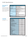
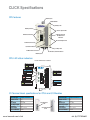
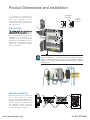
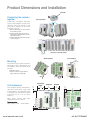
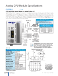
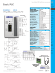
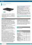
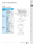
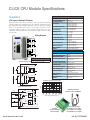
CLICK CPU Module Specifications
C0-00DD1-D
C0-00DD1-D Built-in I/O Specifications - Inputs
<--->
8 DC Inputs/6 Sinking DC Outputs
CLICK PLC CPU, 8 DC input/6 Sinking DC output, 8K steps total program
memory, Ladder Logic programming, built-in RS232C programming port
and additional RS232C Modbus RTU/ASCII communications port (configurable up to 115200 baud). Inputs: 8-pts 24 VDC Sink/Source inputs,
2 commons, isolated. Outputs: 6-pts 5-27 VDC Sinking outputs, 0.1 A/pt,
2 commons, isolated. Removable terminal block included, replacement ADC
p/n C0-16TB.
8 (Sink/Source)
24 VDC
21.6 - 26.4 VDC
X1-2: Typ 5 mA @ 24 VDC
X3-8: Typ 4 mA @ 24 VDC
X1-2: 6.0 mA @ 26.4 VDC
X3-8: 5.0 mA @ 26.4 VDC
X1-2: 4.7 k⏲ @ 24 VDC
X3-8: 6.8 k⏲ @ 24 VDC
X1-2: > 19 VDC
X3-8: > 19 VDC
X1-2: < 4 VDC
X3-8: < 7 VDC
X1-2: 4.5 mA
X3-8: 3.5 mA
X1-2: 0.1 mA
X3-8: 0.5 mA
X1-2: Typ 5 µs Max 20 µs
X3-8: Typ 2 ms Max 10 ms
X1-2: Typ 5 µs Max 20 µs
X3-8: Typ 3 ms Max 10 ms
Logic Side (8 points, green LED)
2 (4 points/common) Isolated
Input Current
Maximum Input Current
Input Impedance
ON Voltage Level
OFF Voltage Level
Wiring Diagram
C0-00DD1-D
Inputs per Module
Operating Voltage Range
Input Voltage Range
Minimum ON Current
24VDC
+
+
Maximum OFF Current
OFF to ON Response
+
+
ON to OFF Response
Status Indicators
Commons
L
+
L
L
C0-00DD1-D Built-in I/O Specifications - Outputs
5 - 27VDC
L
L
+
+
L
5 - 27VDC
24VDC
C0-00DD1-D - 24 VDC Power
Current Consumption 120 mA
Equivalent Input Circuit
Internal Module Circuitry
Optical Isolator
INPUT
X1-X4
Typical
+
Outputs per Module
Operating Voltage Range
Output Voltage Range
6 (Sink)
5-27 VDC
4-30 VDC
Maximum Output Current
0.1 A/point; C3: 0.4 A/common,
C4: 0.2 A/common
Minimum Output Current
Maximum Leakage Current
On Voltage Drop
Maximum Inrush Current
0.2 mA
0.1 mA @ 30.0 VDC
0.5 VDC @ 0.1 A
150 mA for 10 ms
Y1: typ 5 µs; max 20 µs
Y2-6: < 0.5 ms
Y1: typ 5 µs; max 20 µs
Y2-6: < 0.5 ms
Logic Side (6 points, red LED)
2 (4 points/com & 2 points/com) Isolated
OFF to ON Response
+
24 VDC
ON to OFF Response
C1 COM
Status Indicators
Commons
External DC Power
Required
To X2-X4
commons
Optical Isolator
INPUT
X5-X8
Typical
+
20-28 VDC Maximum @ 60 mA
(All Points On)
+
24 VDC
C0-00DD1-D Temperature Derating Chart
C2 COM
8
To X6-X8
commons
Inputs
Equivalent Output Circuit
Internal Module Circuitry
24 VDC
+
+
To Y2-Y6
optical
isolators
+V
Optical Isolator
OUTPUT Y1
Points
6
Outputs
4
2
ZipLink Pre-Wired PLC
Connection Cables and Modules
0
0
32
L
5 - 27 VDC
10
50
20
68
30
85
40
104
50 55 °C
122 131 °F
Surrounding Temperature (°C/°F)
C3 COM
To Y2-Y4
commons
+
From
+V diode
Optical Isolator
OUTPUT Y5
L
5 - 27 VDC
C4 COM
To Y6
common
Note: C3 & C4 are not internally connected.
ZL-RTB20
20-pin feed-through
connector module
www.lamonde.com/click
20-pin connector cable
ZL-C0-CBL20 (0.5 m length)
ZL-C0-CBL20-1 (1.0 m length)
ZL-C0-CBL20-2 (2.0 m length)
+44 (0)1737 824600
CLICK Specifications
General specifications
(all CLICK PLC
products)
These general specifications apply to all
CLICK CPUs, optional I/O modules,
and optional power supply products.
Please refer to the appropriate I/O
temperature derating charts under both
the CPU and I/O module specifications
to determine best operating conditions
based on the ambient temperature of
your particular application.
Environmental Specifications
Operating Temperature
Storage Temperature
Ambient Humidity
Environmental Air
Vibration
Shock
Noise Immunity
Emissions
Agency Approvals
Other
32°F to 131°F (0°C to 55°C)
IEC 60068-2-14 (Test Nb, Thermal Shock)
–4°F to 158°F (–20°C to 70°C)
IEC 60068-2-1 (Test Ab, Cold)
IEC 60068-2-2 (Test Bb, Dry Heat)
IEC 60068-2-14 (Test Na, Thermal Shock)
30% to 95% relative humidity (non–condensing)
No corrosive gases
The level for the environmental pollution is 2 (UL840)
MIL STD 810C, Method 514.2
IEC60068-2-6
JIS C60068-2-6 (Sine wave vibration test)
MIL STD 810C, Method 516.2
IEC60068-2-27
JIS C60068-2-27
Comply with NEMA ICS3-304
Impulse noise 1µs, 1000V
EN61000-4-2 (ESD)
EN61000-4-3 (RFI)
EN61000-4-4 (FTB)
EN61000-4-5 (Surge)
EN61000-4-6 (Conducted)
EN61000-4-8 (Power frequency magnetic field immunity)
RFI: No interference measured between 150-450MHz (5w/15cm)
EN55011:1998 Class A
UL508 CE (EN61131-2)
RoHS instruction conformity
CPU Module Specifications
CPU module
specifications
These specifications apply to all
the CPU modules.
www.lamonde.com/click
Control Method
I/O Numbering System
Ladder Memory (steps)
Total Data Memory (words)
Contact Execution (boolean)
Typical Scan (1k boolean)
RLL Ladder Style Programming
Run Time Edits
Scan
CLICK Programming Software for Windows
Built-in Communication Ports (RS-232)
FLASH Memory
Built-in Discrete I/O points
Number of Instructions Available
Control Relays
Special Relays (system defined)
Timers
Counters
Immediate I/O
Interrupts (external / timed)
Subroutines
For/Next Loops
Math (Integer and Floating Point)
Drum Sequencer Instruction
Internal Diagnostics
Password Security
System Error Log
User Error Log
Memory Backup
Battery Backup
I/O Terminal Block Replacement
AC Power Terminal Block Replacement
Stored Program/Cyclic execution method
Fixed in Decimal
8000
8000
< 0.6us
1-2 ms
Yes
No
Variable / fixed
Yes
Yes (2)
Standard on CPU
8 inputs, 6 outputs
21
2000
1000
500
250
Yes
Yes
Yes
Yes
Yes
Yes
Yes
Yes
Yes
Yes
Super Capacitor
No
ADC p/n C0-16TB
ADC p/n C0-4TB
+44 (0)1737 824600
CLICK Specifications
CPU features
Mounting Tab
Model Number
Sliding Latch
Run/Stop Switch
Discrete Input Points
DIN Rail Slot and
I/O Module Port
Extension
LED Status Indicators
Discrete Output Points
Communications Ports
I/O Status Indicators
Sliding Latch
24 VDC Power Connector
Removable I/O Terminal Block
Mounting Tab
CPU LED status indicators
CLICK LED Status Indicators
POWER LED (Green)
On
Power Good
Off
Power Failure
C0-00DD1-D
C1
RUN LED (Green)
On
CPU Run Mode
Off
CPU Stopped
or Prog. Mode
X1
X2
X3
PWR
On
Off
Self Diagnostic
Error
No Error
TX & RX LED (Green)
X4
C2
RUN
ERR
ERROR LED (RED)
RUN
STOP
X5
INPUT LEDs (Green)
On
Input True
Off
Input False
X6
PORT1
X7
X8
TX1
RX1
C3
TX2
Y1
RX2
Y2
OUTPUT LEDs (Red)
Y3
PORT2
Y4
On Comm Port Data Active
C4
Off No Communication
Y5
On
Output True
Off
Output False
Y6
+V
I/O Terminal block specifications for CPUs and I/O Modules
11-pin Terminal Block Specifications
Connector Type
Number of Pins
Pitch
Wire Range
Wire Strip Length
Screw Size
Screw Torque
ADC Part Number
Pluggable Terminal Block
11 pt
3.50 mm
28-16 AWG
7 mm
M2.0
2.0 to 2.2 lb-inch
C0-8TB
www.lamonde.com/click
20-pin Terminal Block Specifications
11-Pin Terminal Block,
C0-8TB
20-Pin Terminal Block,
C0-16TB
Connector Type
Number of Pins
Pitch
Wire Range
Wire Strip Length
Screw Size
Screw Torque
ADC Part Number
Pluggable Terminal Block
20 pt
3.50 mm
28-16 AWG
7 mm
M2.0
2.0 to 2.2 lb-inch
C0-16TB
+44 (0)1737 824600
Product Dimensions and Installation
Ground Braid
Copper Lugs
It is important to understand the
installation requirements for your CLICK
system. Your knowledge of these
requirements will help ensure that your
system operates within its environmental
and electrical limits.
Panel or
Single Point
Ground
Panel
Plan for safety
Star Washers
This catalog should never be used as a
replacement for the user manual. You can
purchase, download free, or view online
the user manuals for these products. The
C0-USER-M is the publication for the
CLICK PLC. This user manual contains
important safety information that must be
followed. The system installation should
comply with all appropriate electrical
codes and standards.
Star Washers
2"
50.8mm
minimum
2"
50.8mm
minimum
3"
76.2mm
minimum
NOTE: There is a mimimum clearance requirement of 2” (51 mm) between the CLICK
PLC and the panel door or any devices mounted in the panel door. The same
clearance is required between the PLC and any side of the enclosure. A minimum
clearance of 3” (76 mm) is required between the PLC and a wireway or any heat
producing device.
www.lamonde.com/click
PORT1
TX1
RX1
TX2
RX2
PORT2
RUN
PWR
RUN
ERR
CLICK PLCs must be mounted properly to
ensure ample airflow for cooling
purposes. It is important to follow the unit
orientation requirements and to verify that
the PLC’s dimensions are compatible with
your application. Notice particularly
the grounding requirements and the
recommended cabinet clearances.
STOP
Mounting orientation
Air
Flow
+44 (0)1737 824600
Product Dimensions and Installation
Latch tabs
3
Connecting the modules
together
Connecting Modules
CLICK CPUs, I/O modules and power
supplies connect together using the extension ports that are located on the side
panels of the modules (no PLC backplane/base required).
1) Remove extension port covers and slide
the latch tabs forward.
2) Align the module pins and connection
plug, and press the I/O module onto the
right side of the CPU.
3) Slide the latch tabs backward to lock the
modules together.
2
1
Supports up to eight I/O modules
DIN Rail Mounting
Surface Mounting
Mounting
Upper
Mounting Tab
The CLICK PLC system, which includes the
CLICK power supplies, CPU modules, and
I/O modules, can be mounted in one of
two ways.
1) DIN rail mounted
2) Surface mounted using the built-in
upper and lower mounting tabs.
Pull tab
down.
Power Supply
Module
Unit dimensions
These diagrams show the outside dimensions of the CLICK power suppy, CPU,
and I/O modules. The CLICK PLC system
is designed to be mounted on standard
35mm DIN rail, or it can be surface
mounted.
Allow proper spacing from
components within an enclosure.
Push tab
up until...
CPU Module
1.37"
34.9mm
0.102"
2.6mm
2.11"
53.5mm
Lower
Mounting Tab
Click
I/O Module
1.06"
27mm
0.46"
13.5mm
2.95"
75mm
0.37"
9.4mm
other
3.35"
85mm
Maximum system:
Power Supply + CPU + 8 I/O modules.
0.16"
4mm
0.36"
9.2mm
www.lamonde.com/click
"
+44 (0)1737 824600
Product Dimensions and Installation
Unit dimensions
1.37"
34.9mm
Power Supply
0.10"
2.6mm
0.53"
13.5mm
2.95"
75mm
C0-00AC
OUTPUT
24V 0.5A
3.64"
92.4mm
3.35"
85mm
85
NOTE: The dimensions for the
C0-00AC and C0-01AC power
supplies are the same.
24V
0V
G
L
N
INPUT
100-240V
15VA 50-60Hz
0.16"
4mm
CPU Module
0.19"
4.8mm
0.10"
2.6mm
2.11"
53.6mm
0.37"
9.4mm
0.2"
5mm
2.95"
75mm
CLICK
CPU
MODULE
PWR
RUN
ERR
3.35"
85mm
RUN
STOP
PORT1
TX1
RX1
3.66"
93mm
TX2
RX2
PORT2
0.36"
9.2mm
I/O Module
0.33"
8.5mm
1.06"
27mm
0.10"
2.6mm
0.37"
9.4mm
2.95"
75mm
CLICK
I/O
MODULE
3.6"
92.4mm
3.35"
85mm
0.16"
4mm
www.lamonde.com/click
+44 (0)1737 824600