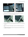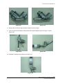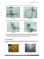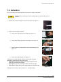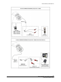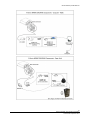
1
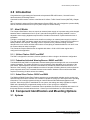
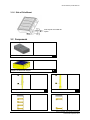
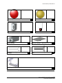
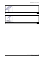
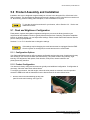
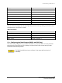
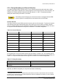
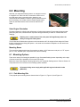
OWNER’S MANUAL Traffic Beacons Models R247C R820C R829C R247 R820 R829 Owner’s Manual | Traffic Beacons Contents 1.0 Precautions...................................................................................................................... 5 2.0 Introduction ..................................................................................................................... 6 2.1 How it Works................................................................................................................................... 6 2.1.1 24 Hour Flasher: R247C and R247 ......................................................................................... 6 2.1.2 Pedestrian Activated Warning Beacon: R820C and R820 ...................................................... 6 2.1.3 School Zone Flasher: R829C and R829 ................................................................................. 6 3.0 Component Identification and Mounting Options ......................................................... 6 3.1 Systems .......................................................................................................................................... 6 3.1.1 Single Beacon Sign Post Round ............................................................................................. 7 3.1.2 Single Beacon Sign Post Square ............................................................................................ 7 3.1.3 Single Beacon 4.5” Post .......................................................................................................... 7 3.1.4 Dual Beacon Horizontal ........................................................................................................... 8 3.1.5 Dual Beacon Vertical ............................................................................................................... 8 3.1.6 Side of Pole Mount .................................................................................................................. 9 3.2 Components ................................................................................................................................... 9 4.0 Tools and Materials Required ....................................................................................... 13 5.0 Product Assembly and Installation .............................................................................. 14 5.1 Flash and Brightness Configuration ............................................................................................. 14 5.1.1 Configuration Options ............................................................................................................ 14 5.1.2 Product Configuration ............................................................................................................ 14 5.1.3 Switch/Dial Function and Options ......................................................................................... 16 5.1.4 Configuring the Flash Duration (R820C and R820 Only) ...................................................... 18 5.2 Antenna Installation (R820C and R820 only) ............................................................................... 20 5.3 Radio Configuration Instructions (R820C and R820 only) ........................................................... 20 5.3.1 Minimum Distance between Systems ................................................................................... 20 5.3.2 Primary/Secondary and Channel Selection .......................................................................... 21 6.0 Mounting ........................................................................................................................ 22 6.1 Mounting Options.......................................................................................................................... 22 6.1.1 Pole Mounting Kits ................................................................................................................ 22 6.2 Mounting the Single Beacon Round Sign Post ............................................................................ 23 6.3 Mounting the Single Beacon Square Sign Post ........................................................................... 24 6.4 Mounting the Single Beacon 4.5” Post ......................................................................................... 24 6.5 Mounting the Side of Pole Mount ................................................................................................. 24 6.6 Mounting the Dual Beacon Vertical .............................................................................................. 24 6.7 Mounting the Dual Beacon Horizontal .......................................................................................... 25 6.8 Mounting the R820 Button ............................................................................................................ 25 6.8.1 Wiring the R820 Button Using an Existing Pole .................................................................... 25 6.9 Mounting Override Switch Box and Pager Unit ............................................................................ 26 6.9.1 Override Switch Box .............................................................................................................. 26 3 © 2012 Carmanah Technologies Corporation Last revised: September 2012 Owner’s Manual | Traffic Beacons 6.9.2 Pager Option – Installing Pager Unit ..................................................................................... 27 6.10 Grounding ..................................................................................................................................... 30 7.0 Activation ....................................................................................................................... 31 8.0 Maintenance and Product Care .................................................................................... 32 9.0 Troubleshooting ............................................................................................................ 33 10.0 Service and Additional Products.................................................................................. 34 10.1 10.2 10.3 Customer Service ......................................................................................................................... 34 Additional Products ....................................................................................................................... 34 Wiring Diagrams ........................................................................................................................... 34 4 © 2012 Carmanah Technologies Corporation Last revised: September 2012 Owner’s Manual | Traffic Beacons 1.0 Precautions Exercise caution when handling the batteries. They are capable of generating dangerous short-circuit currents. Remove all jewelry (bracelets, metal-strap watches, rings) before attempting to handle or remove the batteries. See Section 5.1 for instructions on disconnecting and reconnecting the batteries. The Carmanah R820 Flasher is a warning beacon and is intended to be used as a supplemental emphasis to warning signs located at uncontrolled marked crosswalks, as specified in the 2003 Manual of Uniform Traffic Control Devices, Chapter 4K. It is not a traffic control device. It is the responsibility of the pedestrian to ensure traffic has stopped before entering the crosswalk and this is clearly noted on the information plate mounted with the activation pushbutton. The R820 is only a supplement for an uncontrolled marked crossing. When storing your Carmanah flashing beacon for extended periods of time, ensure the batteries are disconnected from the Energy Management System (EMS). This will help extend the time between charging periods during storage. ESD Precautions and Proper Handling Procedures Dissipate static electricity before handling any system components (Energy Management System, LED lights) by touching a grounded metal object, such as the unpainted metal housing on the system unit. If possible, use antistatic devices, such as wrist straps. Avoid touching the contacts and components on the Energy Management System. Take care when connecting or disconnecting cables. A damaged cable can cause a short in the electrical circuit. Prevent damage to the connectors by aligning connector pins before you connect the cable. Misaligned connector pins can cause damage to system components at power-on. 5 © 2012 Carmanah Technologies Corporation Last revised: September 2012 Owner’s Manual | Traffic Beacons 2.0 Introduction Congratulations on purchasing the Carmanah solar-powered LED traffic beacon, “the world’s most advanced solar LED flashing beacon.” Carmanah’s traffic beacons conform to the Manual of Uniform Traffic Control Devices (MUTCD), Chapter 4K. Using Carmanah’s advanced Energy Management System (EMS), the unit is designed to operate reliably with no scheduled maintenance for up to 5 years except for routine cleaning. 2.1 How it Works The Compact Solar Beacon does not require an external power supply as it operates using solar-charged batteries that are maintenance-free for up to 5 years when the product is properly installed. It can be adjusted to meet varying brightness requirements. Activation of the beacon is performed at the time of installation. The light is completely power-autonomous; therefore no wiring to an external power supply is required. The solar panels, EMS, and battery system are housed in the solar engine. A separate control cabinet or battery cabinet is not required. Trenching of wire to a power source, pavement cutting, and traffic disruption are not a concern with the traffic beacon as everything is contained within the unit itself. It can be mounted wherever there is sunlight. The Carmanah Compact Solar beacon is supplied with either a 10 W or 20 W solar engine that is configured for the application. 2.1.1 24 Hour Flasher: R247C and R247 The R247 is designed for continuous, 24 hour operation in either a single or dual beacon configuration. 2.1.2 Pedestrian Activated Warning Beacon: R820C and R820 The Model R820 and R820C are pedestrian activated warning beacons designed for use at uncontrolled marked crosswalks. The system will flash for a pre-set duration (field adjustable) upon activation of the push button. Spread-spectrum wireless communications activates the beacons across the street, or in advance of the crossing. A typical installation consists of two pairs of flashing beacons, each mounted on poles at opposite ends of the crosswalk.Wireless communication between units means that the R820 requires no trenching of cables across the roadway. 2.1.3 School Zone Flasher: R829C and R829 The R829 and R829C School Zone Flashers operate on a programmable calendar used to set the days and times when the beacon will flash.The calendar is capable of storing up to 500 days worth of operating information. This is easily programmed using an intuitive Microsoft Windows-based graphical user interface. Once the program is established for one system, the settings are easily uploaded to multiple R829 units. Uploading the programmed settings occurs on site quickly from a laptop PC. Alternatively, with the addition of centralized control capabilities, the R829 is compatible with certain 12V third-party wireless communications devices. Contact your local distributor for more information. 3.0 Component Identification and Mounting Options 3.1 Systems 6 © 2012 Carmanah Technologies Corporation Last revised: September 2012 Owner’s Manual | Traffic Beacons 3.1.1 Single Beacon Sign Post Round Solar engine Signal head with LED signal module Mount for 2 3/8” round pole 2 3/8” 3.1.2 Single Beacon Sign Post Square Solar engine Signal head with LED signal module Mount for 2” square pole 5” 3.1.3 Single Beacon 4.5” Post Solar engine Mount for 4.5” post Signal head with LED signal module 5” 7 © 2012 Carmanah Technologies Corporation Last revised: September 2012 Owner’s Manual | Traffic Beacons 3.1.4 Dual Beacon Horizontal Solar engine Top brackets Signal head with LED signal module 21” Bottom brackets 21” 42.5” 42.5” 20 Watt 10 Watt 3.1.5 Dual Beacon Vertical Solar engine Top brackets 21” Signal head with LED signal module 21” Bottom brackets 21” 14.5” 21” 14.5” 20 Watt 10 Watt 8 © 2012 Carmanah Technologies Corporation Last revised: September 2012 Owner’s Manual | Traffic Beacons 3.1.6 Side of Pole Mount Side of pole mount with tilt option 3.2 Components 20 Watt Solar Engine A Compact 10 Watt Solar Engine B 1.75” Square Pole Mount C 2.5” Round Pole Mount D 9 © 2012 Carmanah Technologies Corporation Last revised: September 2012 Owner’s Manual | Traffic Beacons Dual Side Pole Mount E Single Side Pole Mount F Dual Side Pole Mount, no wedge G Single Side Pole Mount, no wedge H Dual Vertical Top Pole Mount I Single Top Pole Mount J Third LED Mount K Dual Horizontal Top Pole Mount L Square Wood Post Mount M 10 © 2012 Carmanah Technologies Corporation Last revised: September 2012 Owner’s Manual | Traffic Beacons 12” LED Light O 8” LED Light P Upload/Program Kit Q Switch R Pager Assembly S Pelco Pipe Adaptor – Mounts to G, H, J, K T Horizontal Mount Support Arm Assembly, no wedge U Horizontal Mount Solar Engine Support Arm V Solar Engine Side of Pole Tilt-Mount W 11 © 2012 Carmanah Technologies Corporation Last revised: September 2012 Owner’s Manual | Traffic Beacons Tilt-Mount: Mounts to G, H, J and K X Tilt-Mount – Mounts C and D Y 12 © 2012 Carmanah Technologies Corporation Last revised: September 2012 Owner’s Manual | Traffic Beacons 4.0 Tools and Materials Required The following tools and materials are required to mount your Carmanah flashing beacon: Imperial socket set Crescent wrench Tap and die set 5/32” allen key Fish tape Level Compass Drill and drill bits Fine-tip felt marker Multi-bit Screwdriver 1/8” hex driver Ladder or lift device Lithium grease Security bit 13 © 2012 Carmanah Technologies Corporation Last revised: September 2012 Owner’s Manual | Traffic Beacons 5.0 Product Assembly and Installation Installation time can be budgeted at approximately ten minutes in the shop plus 30 to 60 minutes in the field per beacon. This time budget is assuming that a pole is already in place in the field to mount the unit on. No trenching, external cabling, traffic disruption, or site remediation is required. To view the electrical connections for your beacon, refer to Section 10.0 Service and Additional Products. 5.1 Flash and Brightness Configuration Flash pattern, daytime and nighttime brightness settings are pre-set at the factory based on your requirements and installation location, typically discussed at the time of ordering. Should the installation location or situation change, you can adjust these settings. Please consult Carmanah Customer Service prior to making any adjustments. Sections 5.1.1 to 5.1.3 describe how to change the settings. If the settings require changing, the main harness must be unplugged from the EMS. Once the system is reconfigured, the main harness can be reconnected. 5.1.1 Configuration Options Your Carmanah flashing beacon offers customer-configurable options using a set of switches and rotary dials located on the circuit board within the EMS housing. They allow control of day intensity, night intensity, LED brightness, flash pattern, flash duration, radio power, channel selection and primary/secondary selection. 5.1.2 Product Configuration Your beacon is factory configured and does not typically need additional configuration. If configuration is necessary, follow the instructions outlined below. To configure your beacon, the solar engine, where the solar panels are mounted, must be opened to access the EMS inside and the harnesses must be disconnected in the order shown below. 1. Remove the two screws attaching the top solar panel lid to the main housing; see Figure 5-1. Figure 5-1 14 © 2012 Carmanah Technologies Corporation Last revised: September 2012 Owner’s Manual | Traffic Beacons 2. Open the lid; see Figure 5-2. Figure 5-2 3. Disconnect the main harness from the EMS; see Figure 5-3. Figure 5-3 4. Remove the four (4) screws and enclosure lid from the EMS; see Figure 5-4 Figure 5-4 On the circuit board within the EMS system housing, there is a plastic block with eight small switches on it (SW1) and two rotary dials (SW2 and SW3); see Figure 5-5 15 © 2012 Carmanah Technologies Corporation Last revised: September 2012 Owner’s Manual | Traffic Beacons 5. Figure 5-5 and Figure 5-6. Figure 5-6 5.1.3 Switch/Dial Function and Options Your Carmanah flashing beacon provides the flexibility of an eight-position DIP switch for user configuration of flash patterns, radio channels, radio power and day / night intensities plus two rotary dials for Brightness and Flash Duration. Table 5-1 shows the function of each switch and which beacon model uses each switch. Table 5-1: Switch/Dial Function and Options SW1 – DIP Switch Switch Function Model 1, 2, 3 Channel Selection R820/R820C 4 Primary/Secondary Selection R820/R820C 5 Day/Night Intensity All 6 Radio Power R820/R820C 7, 8 Flash Pattern All Function Model LED Brightness All Function Model Flash Duration R820/R820C SW2 – Rotary Dial SW2 SW3 – Rotary Dial SW3 For more information on individual switch and rotary dial settings follow the instructions below. For SW1 refer to Table 5-2, Table 5-6, and Table 5-7. For SW2 refer to Table 5-3. 16 © 2012 Carmanah Technologies Corporation Last revised: September 2012 Owner’s Manual | Traffic Beacons For SW3 refer to Table 5-5. The daytime / nighttime intensity settings are adjusted using DIP switch 5 with OFF being the default night time, fixed intensity, and ON being 30% of the daytime intensity setting. The radio power level is adjusted using DIP switch 6 with ON being “high” power and OFF being regular power. Set the DIP switches to the desired flash pattern using Table 5-2 as a guide. Table 5-2: Flash Pattern Settings Dip Switch Settings Flash Pattern Exhibited (in seconds) Flash Character Flash No Flash MUTCD (alternating) Default 0.5 0.5 ON MUTCD (unison) 0.5 0.5 ON OFF 3 quick flashes (unison) 0.1 ON ON Custom setting where default is 3 quick flashes (alternating) 0.1 Switch 7 Switch 8 OFF OFF OFF Flash No Flash Flash No Flash 0.05 0.1 0.05 0.1 0.5 0.05 0.1 0.05 0.1 0.5 Your beacon is factory configured and does not typically need additional configuration. If the settings require changing, the main harness must be unplugged from the EMS. Once the system is reconfigured, the main harness can be reconnected. Increasing brightness level will increase power consumption and possibly affect the autonomy of product. Contact Carmanah Product Support before adjusting. Table 5-3: LED Brightness Settings (SW2) Setting Brightness Level 0 0 1 1 2 2 3 3 4 4 5 5 6 6 7 7 8 8 17 © 2012 Carmanah Technologies Corporation Last revised: September 2012 Owner’s Manual | Traffic Beacons Setting Brightness Level 9 9 A Not used B Not used C Not used D Not used E Not used F Custom Now your beacon is ready for the next steps. Depending on which model you have you will need to start at the right section; follow Table 5-4 below. Table 5-4: Sections Product Section R820C / R820 Proceed to Section 5.1.4 R247C / R247 Proceed to Section 6.0 R829C / R829 Proceed to Section 6.0 5.1.4 Configuring the Flash Duration (R820C and R820 Only) The default factory configuration for your R820C and R820 is a 20 second flash. If a second pedestrian should press the button while the light is flashing, the light will flash for 20 seconds starting from the moment the button was last pressed. The R820C and R820 are factory configured. Only change the flash duration if necessary. 18 © 2012 Carmanah Technologies Corporation Last revised: September 2012 Owner’s Manual | Traffic Beacons You can select the length of time the lights will flash after each button press. There are 15 standard options: Table 5-5: Flash Duration Coded Dial Switch (SW3) Duration Setting Time 0 0:00:10 1 0:00:15 2 0:00:20 3 0:00:25 4 0:00:30 5 0:00:35 6 0:00:40 7 0:00:45 8 0:00:50 9 0:00:55 A 0:01:00 B 0:02:00 C 0:03:00 D 1:00:00 E 6:00:00 If the settings require changing, the main harness must be unplugged from the EMS. Once the system is reconfigured, the main harness can be reconnected. To change the flash duration, turn the coded dial (SW3) to the desired setting. This is easily done with a small flathead screwdriver. For a picture of SW3 refer to Figure 5-6 in Section 5.1.2 Product Configuration. Each of the R820 units in a crosswalk system must be configured individually, with the same flash duration setting. 19 © 2012 Carmanah Technologies Corporation Last revised: September 2012 Owner’s Manual | Traffic Beacons 5.2 Antenna Installation (R820C and R820 only) The main harness must be disconnected during this procedure. Mount and connect the antenna to the EMS before power is applied to the system. This prevents damage to the radio module. The antenna is shipped inside the housing when it comes from the factory. It is wrapped in foam and placed on the left side of the enclosure. To set up the antenna, complete the following steps: 1. Remove the screws securing the lid to the housing. 2. Open the lid and disconnect the main harness from the EMS. 3. Remove and unwrap the coaxial cable and antenna from inside the housing. 4. Remove the mounting screw for the antenna bracket, located on the side of the housing; see Figure 5-7. 5. Insert the co-axial cable through the hole in the side of the housing, and carefully thread the co-axial cable onto the gold-colored fitting on the electronics enclosure from where it was just removed. 6. Pull the cable through the hole and position the antenna bracket over the mounting screw hole on the side of the housing. 7. Use the mounting screw to attach the antenna bracket to the housing; see Figure 5-8. Figure 5-7 Figure 5-8 5.3 Radio Configuration Instructions (R820C and R820 only) Below are the configuration and assembly instructions for your Carmanah R820 flashing beacon. 5.3.1 Minimum Distance between Systems The minimum distance that must be maintained between independent systems using the same radio channel is 4.0mi (6.5km). If independent systems are required to be located less than 4.0mi (6.5km) from each other, the radios in each independent system MUST be set to different channels. Please refer to Section 5.3.2 Primary/Secondary and Channel Selection for information on setting the radio channel. 20 © 2012 Carmanah Technologies Corporation Last revised: September 2012 Owner’s Manual | Traffic Beacons 5.3.2 Primary/Secondary and Channel Selection Your R820 crosswalk system consists of two or more units that communicate with each other to flash 1 together. Each system is shipped set to a factory default of one Primary and one or more Secondary , all at Channel 0. Channel selection is determined by DIP switches 1, 2 and 3. The primary/secondary settings are determined by DIP switch 4; see below. If the settings require changing, the main harness must be unplugged from the EMS. Once the system is reconfigured, the main harness can be reconnected. Channel Selection The channel chosen for each R820 must be the same in each unit of that system. To prevent one system from interfering with other systems within range 4.0mi (6.5km) you can set each to a specific channel. Three (3) channel switches give the possibility of eight (8) unique channels as shown in Table 5-6, below. For a picture of the DIP switch refer to Figure 5.6 in Section 5.1.2 Product Configuration. Table 5-6: Channel Selection Channel DIP Switch 1 DIP Switch 2 DIP Switch 3 0 off off off 1 on off off 2 off on off 3 on on off 4 off off on 5 on off on 6 off on on 7 on on on For a system (two or more units) there must be only one primary, or master, unit – the remaining units in the system must be configured as secondary. DIP switch 4 determines the primary/secondary setting; see Table 5-7. For a picture of the switch refer to Figure 5.6 in Section 5.1.2 Product Configuration. Table 5-7: Primary/Secondary Unit Designation DIP Switch 4 Primary on Secondary off Now that your R820 is configured you can proceed to Section 6.0 Mounting. 1 Primary/Secondary is a term for a communication protocol where one device or process has control over another (or others). Once a primary/secondary relationship between devices is established, the direction of control is always from the primary to the secondary(s). 21 © 2012 Carmanah Technologies Corporation Last revised: September 2012 Owner’s Manual | Traffic Beacons 6.0 Mounting Now that your Carmanah flashing beacon is configured it’s time to install the unit. Each unit will be connected to either one or two LED arrays using a mounting option based on your requirements and installation location, typically discussed at the time of ordering. You will also need to install the push-button switch for the R820 and the manual override switch for the R829. Solar Engine Orientation Full solar exposure is critical to the performance of solar engine system. Ensure that the beacon solar panel has year-round, unrestricted sun exposure throughout the day to allow for unobstructed solar charging. Shading even a small portion of the solar panel will significantly reduce its ability to charge the battery bank. The 10 Watt and 20 Watt solar engines must be mounted at a 45° tilt using the fixed wedge tilt. Ensure that the solar panels are facing the equator – due south in the northern hemisphere or due north in the southern hemisphere. Mounting Bases The unit will be shipped with a base for mounting on either a 2 3/8” diameter round pole, a 1.75” square pole, or a 4½” diameter pole, as specified at the time of ordering. 6.1 Mounting Options There are a variety of mounting kits possible for your Carmanah flashing beacon depending on the style of mount as well as the possibility of one or two LED arrays. Below are a few of the popular mounting options for your Carmanah flashing beacon. Refer to Section 3.2 Components for a full overview of the mounting options available. All external wiring must comply with applicable regional electrical codes (NEC/CEC). 6.1.1 Pole Mounting Kits Three popular pole mounting kits are shown below in Figure 6-1, Figure 6-2, and Figure 6-3. 22 © 2012 Carmanah Technologies Corporation Last revised: September 2012 Owner’s Manual | Traffic Beacons Figure 6-1: Top Pole Mount and Single LED Array Mount Figure 6-2: Dual Beacon Pole Mount Figure 6-3: Horizontal Mount 6.2 Mounting the Single Beacon Round Sign Post Mount the unit on an existing 2 3/8” diameter round sign post. First drill a ¼” hole in the sign post to accommodate a ¼-20 carriage bolt. This hole is used to secure the beacon. Next, install the unit on the sign post ensuring the flashing beacon is pointed in the desired direction. Use the supplied hardware to secure the beacon to the post. Single Beacon Round Sign Post 23 © 2012 Carmanah Technologies Corporation Last revised: September 2012 Owner’s Manual | Traffic Beacons 6.3 Mounting the Single Beacon Square Sign Post To mount, install the unit on an existing 1.75” diameter square sign post ensuring the flashing beacon is pointed in the desired direction. Use the supplied hardware to secure the beacon to the post. Single Beacon Square Sign Post 6.4 Mounting the Single Beacon 4.5” Post To mount the single beacon 4.5” post follow the directions below. 1. Attach the solar engine to the adaptor hub by threading into the hole. Place the adaptor hub onto the pole and finger-tighten the bolts. Install the Signal Head 1. Install the signal head housing onto the upper support arm. 2. Connect the signal wire from the EMS to the LED Signal Head. Single Beacon 4.5” Post 3. Attach the bottom bracket, then level the solar engine and tighten the top cap bolts. The bottom bracket can be affixed with bolts or stainless steel straps. 4. Tighten the setscrew on the cap and position the lenses towards oncoming traffic. 5. Tighten the nuts inside the signal head. 6.5 Mounting the Side of Pole Mount Attach the side of pole mount to the pole using adequate hardware (not supplied). Install the Signal Head 1. Install the signal head housing onto the upper support arm. 2. Connect the signal wire from the EMS to the LED Signal Head. 3. Attach the bottom bracket, then level the solar engine and tighten the top cap bolts. The bottom bracket can be affixed with bolts or stainless steel straps. 4. Tighten the setscrew on the cap and position the lenses towards oncoming traffic. 5. Tighten the nuts inside the signal head. Side of Pole Mount 6.6 Mounting the Dual Beacon Vertical To mount the dual beacon vertical follow the directions below. 1. Attach the solar engine to the adaptor hub by threading into the 24 © 2012 Carmanah Technologies Corporation Last revised: September 2012 Owner’s Manual | Traffic Beacons hole. Place the adaptor hub onto the pole and finger-tighten the bolts. Install the Signal Heads 1. Install the signal head housing onto the upper support arm. 2. Connect the signal wire from the EMS to the LED Signal Head. 3. Attach the bottom brackets, then level the solar engine and tighten the top cap bolts. The bottom brackets can be affixed with bolts or stainless steel straps. 4. Tighten the setscrew on the cap and position the lenses towards oncoming traffic. 5. Tighten the nuts inside the signal heads. 6.7 Mounting the Dual Beacon Horizontal Dual Beacon Vertical To mount the dual beacon horizontal, follow the directions below. 1. Attach the solar engine to the adaptor hub by threading into the hole. Place the adaptor hub onto the pole and finger-tighten the bolts. Install the Signal Heads 1. Install the signal head housing onto the upper support arm. 2. Connect the signal wire from the EMS to the LED Signal Head. Dual Beacon 3. Attach the bottom brackets, then level the solar engine and tighten the Horizontal top cap bolts. The bottom brackets can be affixed with bolts or stainless steel straps. 4. Tighten the setscrew on the cap and position the lenses towards oncoming traffic. 5. Tighten the nuts inside the signal heads. 6.8 Mounting the R820 Button 6.8.1 Wiring the R820 Button Using an Existing Pole ADA regulations specify that the button should be 42” from the ground. Important – Switch 1 must be disconnected at the solar engine until the harness terminal-ends are attached to the pushbutton switch. 1. Drill and tap the screw holes, then file the edges to avoid damaging the wires during installation; see Figure 6-4. Figure 6-4: Screw Holes 25 © 2012 Carmanah Technologies Corporation Last revised: September 2012 Owner’s Manual | Traffic Beacons 2. Next, attach the button plate and the button sign to the pole using a socket set to tighten the bolts; see Figure 6-5. Figure 6-5: Push-button plate (left) and sign (right) 3. Use fish tape to run the harness from the solar engine to the button; see Figure 6-6. 4. Carefully thread the harness through the mounting pole; see Figure 6-7. Figure 6-6: Fish Tape Figure 6-7: Mounting Pole and Harness 5. Attach the harness from the solar engine to the button contacts. This is the long harness with the two ring terminals; see Figure 6-8 and Figure 6-9. Figure 6-8: Button Figure 6-9: Button Plate 6.9 Mounting the R829 Override Switch Box and Pager Unit The R829 comes with a manual override switch or a pager unit. 6.9.1 Override Switch Box The manual override switch is used for programming the unit in the field and to put the R829 into continuous flash mode. 1. To begin, follow steps 1, 3 and 4 of Section 6.8 procedure shown on the previous page for drilling holes. 2. Next, identify the harness labeled “switch 2” and connect the manual override switch harness leading from the manual override switch box; see Figure 6-10. 26 © 2012 Carmanah Technologies Corporation Last revised: September 2012 Owner’s Manual | Traffic Beacons Figure 6-10 3. Fasten the switch box to the pole with the supplied hardware and close the hinged top. 6.9.2 RTC Pager Option – Installing Pager Unit 1. Open the pager enclosure box, shown on the next page, by removing the four fasteners on the lid. (See Figure 6-11 and Figure 6-12). Inside will be a harness and fitting. Remove and set aside. Figure 6-11 Figure 6-12 2. Once open, insert pager unit so that the connectors slide through the opening; see Figure 6-13 and Figure 6-14. 27 © 2012 Carmanah Technologies Corporation Last revised: September 2012 Owner’s Manual | Traffic Beacons Figure 6-13 Figure 6-14 3. While pushing the unit tight against the gasket material, install and tighten the mounting screw. 4. Connect the harness to the pager; see Figure 6-15 and Figure 6-16. Figure 6-15 Figure 6-16 5. To connect the power for the unit, locate the two harnesses, each labeled “12V DC,” and connect one to the other. 6. Take the remaining harness, labeled “Switch 2”, and connect it to the EMS harness with the same name. 7. To install the antenna, remove the back plate from the elbow provided by loosening the two screws; see Figure 6-17 and Figure 6-18. 28 © 2012 Carmanah Technologies Corporation Last revised: September 2012 Owner’s Manual | Traffic Beacons Figure 6-17 Figure 6-18 8. Remove the nut from the pager antenna hardware, and set it aside. 9. Take the cable from the antenna and feed the full length through the pipe; see Figure 6-19 and Figure 6-20. Figure 6-19 Figure 6-20 10. Thread the antenna onto the fitting; see Figure 6-21. Figure 6-21 29 © 2012 Carmanah Technologies Corporation Last revised: September 2012 Owner’s Manual | Traffic Beacons 11. Once complete, feed the cable through the other opening; see Figure 6-22 and Figure 6-23. Figure 6-22 Figure 6-23 12. Then replace the back plate and tighten the screws; see Figure 6-24 and Figure 6-25. Figure 6-24 Figure 6-25 13. Using a screwdriver, carefully remove the knock-out from the side of the solar engine housing. Insert the male end of the fitting, and use the nut that was set aside earlier to tighten the fitting onto the housing. Ensure that the pager antenna is in an upright orientation when the unit is installed. Coil the remaining cable under the EMS before connecting the antenna to the unit. 6.10 Grounding The engine must be properly grounded. The chassis ground is shown in pictures 6-26 and 6-27 below. The proper grounding techniques will be specific to site location; local electrical code needs to be followed. Figure 6-26 Figure 6-27 30 © 2012 Carmanah Technologies Corporation Last revised: September 2012 Owner’s Manual | Traffic Beacons 7.0 Activation Once your beacon is securely fastened to its mount it is ready for activation. LEDs must be connected prior to connecting batteries, otherwise they will not activate. 1. Remove the screws securing the top cover and open; see Figure 7-1. Figure 7-1 2. Connect the harnesses as follows: a. Connect the main harness to the EMS; see Figure 7-2. Figure 7-2 b. Connect the LED(s) and switch connections; see Figure 7-3. Figure 7-3 c. Ensure LED’s are connected then connect the battery(s); see Figure 7-4. Figure 7-4 d. Connect the solar panel(s); see Figure 7-5. Your beacon is now operational. Check to see the light is flashing following the model-specific instructions below: R247C/R247: The light will flash as soon as all components and power are connected to the system. R820C/R820: Press the push-button switch to activate the light. R829C/R829: Engage the manual override switch to activate the light. If the light does not flash, refer to Section 9.0 Troubleshooting. Figure 7-5 31 © 2012 Carmanah Technologies Corporation Last revised: September 2012 Owner’s Manual | Traffic Beacons The main harness connection to the EMS acts as a power disconnecting means. When any maintenance activity is being performed on the beacon, unplug the main harness connector from the EMS. 8.0 Maintenance and Product Care The Traffic Beacon solar engines are designed to operate reliably for years with virtually no need for maintenance. Carmanah recommends routine inspections of the solar panels to ensure that they are clean and unobstructed by anything that could prevent the effectiveness of the solar charging, including: dirt and dust snow leaves debris shade that may have developed after installation due to adjacent plant growth The frequency of the inspections depends on location and local weather patterns. A yearly visual inspection of the Traffic Beacon solar engines is typically sufficient. Batteries Exercise caution when handling the battery packs. They are capable of generating enormous short-circuit currents. Remove all jewelry (bracelets, metal-strap watches, rings) before attempting to handle or remove the battery packs. The battery is a sealed rechargeable lead-acid 12V battery. Consult your local municipal by-laws for information on recycling the cells when replacing. Do not discard these cells in the garbage – please recycle! Energy Management System (EMS) Recycling Production of the EMS required the extraction and use of natural resources. The EMS may contain substances that could be harmful to the environment or human health if improperly handled at the product’s end of life. In order to avoid release of such substances into the environment and to reduce the use of natural resources, we encourage you to recycle the EMS in an appropriate way that will ensure most of the materials are reused or recycled appropriately. Check your local municipality for electronics recyclers. The symbol shown to the left indicates that this product complies with the European Union’s requirements according to Directive 2002/96/EC on waste electrical and electronic equipment (WEEE). 32 © 2012 Carmanah Technologies Corporation Last revised: September 2012 Owner’s Manual | Traffic Beacons 9.0 Troubleshooting If the Light is not Flashing 1. Check the battery connection and the LED array connection to ensure that the connectors are fully inserted. Check to see that the jumper is connected to switch 2 (R247C/R247 only). As the light is designed to function as soon as the battery is plugged in and the jumper is connected, this should be fairly simple to diagnose. Jumper Connector (R247C/R247 only) LEDs must be connected prior to connecting batteries, otherwise they will not activate. Follow the steps below to ensure the LEDs are connected correctly. 2. Disconnect the harnesses from the Energy Management System (EMS) in the following sequence: a. Disconnect the solar panel connections. b. Disconnect the batteries. c. Disconnect the Light Emitting Diodes (LEDs) and switch connections. 3. Now reconnect the harnesses in the following sequence: a. Connect the LEDs and switch connections b. Connect the batteries. c. Connect the solar panel connections. If the Light is Exhibiting Irregular Flash Patterns Your Carmanah flashing beacon may exhibit irregular flasher patterns under certain conditions. If you notice that your Beacon is flashing irregularly, it may be a result of one of the following conditions: 1. Low battery condition: Under a low battery condition, the Beacon will exhibit the following flash pattern: on 0.1 second, off 2.5 seconds, repeat. If your light is exhibiting this flash code you will need to charge the unit's battery. This can be done in several ways. If there is sufficient solar insolation, disconnect the LEDs and allow the unit to charge for three to five days. Batteries can also be charged by placing the unit under high-powered halogen flood lights for three days. Placing the floodlights closer than 24 inches (60 cm) from the solar panel will cause it to overheat and cause damage. Also, ensure your unit’s dip switch is set to the lowest candela setting, as it is likely that the unit is drawing more energy than the solar input. During periods of storage, batteries should be stored in a cool dry place, and be charged every 2 months to maintain voltage levels and reduce sulfation of the battery plates. For a warmer storage temperature, the batteries will need to be charged more frequently. 2. The flasher has not been exposed to sunlight in 24 hours: Under this condition the light will display the following flash pattern: on 0.1second, off 0.5 seconds, repeat. In this situation it is best to expose the unit to sunlight or high-powered halogen flood lamps. This measure should stimulate the unit to begin producing its specified flash code. If Your Units are Having Difficulty Communicating 1. Make sure the units are set to the correct primary/secondary setting. Refer to Section 5.3.2 Primary/Secondary and Channel Selection. 2. Try changing channels. Refer to Section 5.3.2 Primary/Secondary and Channel Selection. If your beacon still refuses to operate correctly, contact Carmanah Technologies Corp. or your authorized Carmanah distributor. 33 © 2012 Carmanah Technologies Corporation Last revised: September 2012 Owner’s Manual | Traffic Beacons 10.0 Service and Additional Products 10.1 Customer Service This product is covered by the Carmanah Limited Warranty. Before contacting Carmanah’s Customer Service Department, please have the following information available: Serial number – located on the outside of the solar engine enclosure. A brief description of the problem Details of the installation. To contact Carmanah’s Customer Service Department: Mail: Carmanah Technologies Corporation 250 Bay Street Victoria, BC Canada V9A 3K5 Phone: 1.250.380.0052 1.877.722.8877 (U.S. and Canada Toll Free) Fax: 1.250.380.0062 Email: [email protected] Website: carmanah.com 10.2 Additional Products Carmanah offers a variety of solar-powered and energy efficient LED lighting products. For traffic applications Carmanah also manufactures solar LED Outdoor Lighting products. For more information, please visit our website at carmanah.com. 34 © 2012 Carmanah Technologies Corporation Last revised: September 2012 Owner’s Manual | Traffic Beacons 10.3 Wiring Diagrams 35 © 2012 Carmanah Technologies Corporation Last revised: September 2012 Owner’s Manual | Traffic Beacons 36 © 2012 Carmanah Technologies Corporation Last revised: September 2012 Owner’s Manual | Traffic Beacons 37 © 2012 Carmanah Technologies Corporation Last revised: September 2012 Owner’s Manual | Traffic Beacons 38 © 2012 Carmanah Technologies Corporation Last revised: September 2012 © 2012, Carmanah Technologies Corporation www.carmanah.com Technical Support: [email protected] Toll Free in Canada and the U.S.: 1.877.722.8877 International: 1.250.380.0052 | Fax: 1.250.380.0062 Number: 50749_Traffic_Beacon_Manual_RevL 50749