1
Orville
Operating Manual
for software version 3.0
Part No: 141032
Manual Release 1.2
4 April, 2003
©1999 Eventide Inc., One Alsan Way, Little Ferry, NJ, 07643 USA
Harmonizer is a registered trademark of Eventide Inc. for its audio special effects devices incorporating pitch shift.
Orville and Ultrashifter are trademarks of Eventide Inc.
This Page Intentionally Left Blank
Orville Operating Manual
Table of Contents
HOW TO USE THIS MANUAL ..............................................................................................................................................................................5
OVERVIEW AND QUICKSTART _____________________________________________________________________ 6
THE BIG PICTURE ................................................................................................................................................................................................6
KNOBS, KEYS, AND JACKS ................................................................................................................................................................................8
The Front Panel
8
The Back Panel
12
GETTING AROUND AND ALTERING PARAMETERS .......................................................................................................................................16
Adjusting the Brightness and Contrast of the Display
16
The “Areas” of Orville
16
Understanding the Display and SOFT KEYS
18
Using the Cursor Keys, the SELECT key, the NUMERIC KEYPAD, and the KNOB
20
Ganged Parameters
20
Using the Cursor Keys and the KNOB in the PROGRAM and Routing Storage Areas
21
Entering or Changing Text
23
QUICKSTART OR “NEARLY INSTANT GRATIFICATION”..............................................................................................................................24
Hooking Up
24
Loading Routing Configurations
26
The I/O Identifier
28
Setting Input Levels
29
Effecting Things
30
“Panic” Muting
30
Loading Programs
30
Parameters
32
“Tweaking” and Saving “Tweaks”
34
Wrap Up 35
OPERATION _____________________________________________________________________________________ 36
Mounting and Handling
Memory Cards
36
36
THE COMPREHENSIVE INPUT / OUTPUT SCHEME .......................................................................................................................................38
Signal Flow Inside Orville
38
Selecting “Sources” for Each DSP
38
Selecting “Sources” for the Outputs
39
Storing and Loading Routing Configurations
40
Loading a Routing Remotely Via MIDI
41
Signal Flow Examples
41
Analog Serial Quad _______________________________________________________________________________ 43
Dual Quad 1 ___________________________________________________________________________________ 44
Digital Parallel Quad ______________________________________________________________________________ 45
Analog Dual Stereo _______________________________________________________________________________ 46
Mono To Quad Serial With (Truly) Dry Signal Added to Outputs ________________________________________________ 46
Programs’ Effect on Routing Decisions
48
Controlling Levels
51
The Levels Meters
51
Controlling the Level of the Analog and Digital Inputs
53
Input Levels, Wet/Dry Ratios, and Output Levels for Each DSP
54
Controlling the Level of the Analog and Digital Outputs
55
DIGITAL SETUP ..................................................................................................................................................................................................56
Manual Release 1.2
Orville Operating Manual
1999 Eventide Inc.
Page 1
Orville Operating Manual - Contents
Digital Setup Overview
S/P DIF 56
Sampling Rates
Using the Internal Clock
Selecting The Internal Clock’s Rate
The Status Of The Digital I/Os When Using The Internal Clock
Understanding The “System Sampling Rate And External Sync Indicator” When Using The Internal Clock
Using an External Clock
Selecting The External Clock
The Status Of The Digital I/Os When Using The External Clock
Understanding The “System Sampling Rate And External Sync Indicator” When Using The External Clock
Sample Rate Conversion (SRC)
Word Length (Bits)
Input Word Length
Output Word Length
56
57
57
57
58
59
59
60
60
61
62
63
63
63
BYPASSING AND MUTING .................................................................................................................................................................................64
System Bypass
64
Machine Bypass
65
EXTERNAL CONTROLLERS................................................................................................................................................................................66
Setting Up the External Controllers
66
Foot Pedals 1 and 2
66
MIDI Setup
67
Changing Banks Via A MIDI Controller Message
67
External Modulation and Trigger Menu Pages
70
“Manually” Selecting an External Controller For Modulation
70
“Manually” Selecting the External Controller For Triggers
72
External Controller Selection
75
“Automatically” Selecting a MIDI External Controller
76
Scaling the External Controller
76
The Concept Behind “Redirection” - External Assigns 1-8 and Trigs 1 &2
79
Remote Controlling Parameters
83
Remote Controlling Triggers
83
MIDI Groups
1
Configuring the MIDI Group
1
PROGRAM LOAD, SAVE, DELETE, ETC. ..........................................................................................................................................................79
Banks 79
Creating a New Bank or Renaming an Old Bank
80
The “Size” of a Program and Its Ramifications for Storage
80
Loading Programs
81
Loading a Program Remotely
82
Loading A Program Via A MIDI Program Change Message
82
Changing Banks Via A MIDI Controller Message
82
Triggering the Next or Previous Program To Load
83
Saving a Program
83
Copying Programs
84
Updating a Program
84
Renaming A Program
84
Deleting a Program
84
“Linking” Programs
85
Comparing a Currently Loaded Program With The Original (Saved) Version
87
PARAMETERS .......................................................................................................................................................................................................88
System Tempo
88
System Timer
89
Taps
90
Page 2
Orville Operating Manual
1999 Eventide Inc.
Manual Release 1.2
Textblocks
Graphics and Curves
Orville Operating Manual - Contents
90
90
STORING AND LOADING SETUPS.....................................................................................................................................................................92
MISCELLANEOUS SETUP OPTIONS ..................................................................................................................................................................92
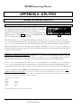
APPENDIX A -UTILITIES _________________________________________________________________________ 94
TRANSMITTING AND RECEIVING DATA .........................................................................................................................................................94
Setting Up the Serial Port
94
Dumping Data and Receiving Data Dumps
95
Controlling One Orville from Another Orville
96
Sending A Program From One Orville to Another
96
Sequencing With MIDI
97
CONNECTING USER-SUPPLIED CRYSTALS AND EXTERNAL CLOCKS ............................................................................................................98
SERVICE AND START-UP OPTIONS ..................................................................................................................................................................99
Fixing Internal Memory Problems
99
Fixing Memory Card Problems
100
Changing the internal battery
101
Clear Setup
101
Software Version and Accessories
101
Start-Up Options
102
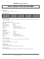
ELECTRICAL SPECIFICATIONS __________________________________________________________________ 104
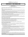
WARRANTY INFORMATION _____________________________________________________________________ 106
INDEX _________________________________________________________________________________________ 108
Manual Release 1.2
Orville Operating Manual
1999 Eventide Inc.
Page 3
Orville Operating Manual
This Page Intentionally Left Blank
Page 4
Orville Operating Manual
1999 Eventide Inc.
Manual Release 1.2
Orville Operating Manual
IMPORTANT SAFETY INFORMATION
• Before powering up the unit, check that the voltage selector on the back panel is set correctly.
• Do not remove any covers or panels from the unit when the power is connected.
• No operator access to the internals of the unit is permitted - servicing must be performed by qualified
personnel only.
• The unit must not be operated with a damaged or ungrounded power cord.
• Suitable ventilation must be provided for the unit at all times. In particular, the rear and side vents must
not be obstructed.
HOW TO USE THIS MANUAL
The first and second chapters of this manual are the most important ones. The first is the Overview and
Quickstart chapter. In it you will find essential information regarding the front panel, the back panel, and
the general structure of Orville. After these preliminaries are out of the way, you’ll start using Orville and
learning the basic methodologies that you will employ whenever you use Orville.
The Overview and Quickstart chapter is not meant to be complete. It’s meant to get you up and running
fast, circumventing thornier issues in favor of speed. If you would like to know more about a particular
topic discussed in this chapter, look to the abundant references contained therein. They’ll point you to
“chunkier” discussions in the remainder of the manual.
Ideally, we would have you read through the Overview and Quickstart guide with Orville in front of you,
following the examples. After you finish the Quickstart guide, we’d have you play with Orville for a while.
Once the initial “new box euphoria” wears off a bit, we’d have you sit down and read the Operation chapter. A true appreciation and mastery of Orville cannot be obtained without reading the manual! We’d have
you consult the appendices only when you need specific, technical information. Finally, when you need to
find information days, weeks, months, and years down the road, we’d have you use the comprehensive Table of Contents and Index.
Note: This manual is intended for Orville units that were manufactured after 1 April 2003 running version
3.0 software. Most, but not all, of it will apply to other units as well.
Manual Release 1.2
Orville Operating Manual
1999 Eventide Inc.
Page 5
Orville Operating Manual
OVERVIEW AND QUICKSTART
THE BIG PICTURE
The Eventide Orville is a programmable, multichannel, multipurpose, dual digital signal processor (DSP), 24
bit digital audio signal processor with UltraShifter capability. That’s a lot of adjectives! It is the successor
to a long, proud line of digital signal processors that stretches back to a time when most audio manufacturers didn’t know digital audio from Morse code.
Orville is loaded with features that put it in a class by itself. It has four analog inputs, four analog outputs,
four digital inputs, and four digital outputs that can all be used simultaneously. Routing among them is completely flexible (“anything to anything”)! What’s more, Orville houses two independent signal processors,
each having four inputs and four outputs (imaginatively dubbed “DSP A” and “DSP B”). The two processors can be run in parallel, in series, or in any mutant variation thereof.
The variety and depth of the programs that run on the DSPs are truly amazing, from lush reverbs, to choruses, to flanges, to delays, to pitch shifters, to dynamics, to EQs, to filters, to distortions, to synthesizers, to
samplers, to ring modulators, and everything in-between. Most frequency and time-dependent parameters
(e.g. delays, LFO's) synchronize to a system tempo for ease of use. And if that’s not enough, DSP A boasts
nearly three minutes of sample time in addition to the 40 seconds of delay time found on both DSP A and
DSP B!
And for the user who is interested in making his or her own programs (if the huge number of factory programs aren’t enough!), Orville continues the “modular programming paradigm” that made the DSP4000
famous. Programs are composed of individual building blocks, or “modules,” that allow the user to create
original programs. Inspiration and creativity are given no bounds. . .
As you read this manual, it may be easy to “lose sight of the forest for the trees.” Always bear in mind the
following:
•
Orville houses two independently running DSPs (digital signal processors). They are lovingly referred to
as “DSP A” and “DSP B.” Although they are both always running, you can only view the parameters for
one DSP at a time. Use the DSP A/B key to toggle the display between the two DSPs.
•
Each DSP runs “programs” that are stored in the system. “Programs” are the algorithms that manipulate your audio. With the exception of “large sampler programs” and some “long delay” programs, any
program can be run on either DSP. Like two separate effects boxes, the parameters for the program
running on DSP A are totally independent of the parameters for the program running on DSP B. Like
two separate effects boxes, you can connect the outputs of one DSP to the inputs of the other, or use
them completely independently.
•
Orville has four analog inputs, four analog outputs, four digital inputs, and four digital outputs that can
all be used simultaneously. DSP A has four inputs and four outputs, and DSP B has four inputs and four
outputs. Any input can be connected to any output. It’s that simple (conceptually)!
Page 6
Orville Operating Manual
1999 Eventide Inc.
Manual Release 1.2
Orville Operating Manual
Never lose sight of the above facts!!! They are the foundation upon which we will build our understanding!!!
Manual Release 1.2
Orville Operating Manual
1999 Eventide Inc.
Page 7
Orville Operating Manual
KNOBS, KEYS, AND JACKS
If this is your first time learning Orville, don’t be put off by some of the rather in-depth descriptions that
will follow; they exist for your future reference (once you understand Orville and need a quick bit of information). For now,
concentrate on what the various knobs and jacks are called. Their use will be explained progressively
throughout the rest of this manual.
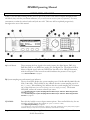
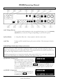
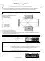
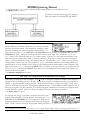
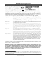
The Front Panel
A) Level Meters
These measure the four signals at the analog inputs, the digital inputs, DSP A in,
DSP B in, DSP A out, DSP B out, analog out, and digital out. The highest LED indicates a clipped signal, and every LED below that falls off at -3dB per decrement,
with the exception of the bottom one which indicates the presence of any signal.
→ See The Levels Meters on page 51.
B) System sampling rate and external sync indicator.
The top four LEDs display the system sampling rate of Orville: 96 kHz, 88.2 kHz, 48
kHz, or 44.1 kHz. When solidly lit, they indicate that the system sampling rate is exact (+/- 0.05%). When blinking, they indicate that the system sampling rate is between
one of the fixed rates (the LED corresponding to the nearest sampling rate blinks). The bottom
LED, EXT, reflects the current external sync status.
→ See Understanding The “System Sampling Rate And External Sync Indicator” When Using The Internal Clock on page 59.
→ See Understanding The “System Sampling Rate And External Sync Indicator” When Using The External Clock on page 61.
C) BYPASS
Press this key briefly to access bypass menu options. Press and hold this key for one
second to actually bypass the system (the “system” is Orville as a whole).
→ See Bypassing and Muting on page 64.
→ To change the “one second hold time,” alter the “key hold” parameter on the [misc] menu page in
the SETUP area (you may have to press the SETUP key several times to find it).
Page 8
Orville Operating Manual
1999 Eventide Inc.
Manual Release 1.2
Orville Operating Manual
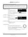
D) Bypass Status LEDs:
•
•
•
A illuminated = DSP A is bypassed
B illuminated = DSP B is bypassed
both A and B blinking = system is bypassed
→ See Bypassing and Muting on page 64.
E) SOFT KEYS
These four keys select the menus or events described on the bottom line of the display.
→ See Understanding the Display and SOFT KEYS on page 18.
F) The display
The display tells you what’s going on. In the upper left-hand corner of the display is
the letter “A” or “B.” “A” indicates that what is shown on the display reflects the
status of DSP A. Similarly, “B” indicates that what is shown on the display reflects
the status of DSP B. (The menu pages in the BYPASS, LEVELS, and SETUP areas have some displays that
are common to both DSPs. In these areas, the “A” or “B” is irrelevant. However, in the PROGRAM, PARAMETER,
and Patch Editor areas, menu pages are DSP specific.) The remainder of the top line displays the
program name running on the currently displayed DSP and the current display area
you’re working in. The bottom line is dedicated to the four SOFT KEYS directly below the display. The middle section of the display changes depending on what
you’re doing!
→ See Understanding the Display and SOFT KEYS on page 18.
G) DSP A/B
Press this key to toggle the display between the status of DSP A and DSP B. The
upper left-hand corner of the display changes when you press this key; the “A” toggles to “B” and vice versa. Both DSPs are always running, but the display only shows the parameters per-
taining to one of them at a time.
H) PROGRAM
Press this key briefly to access program functions such as loading, saving, deleting,
etc. The DSP you are loading into or saving from is referred to in the left-hand corner of the display (“A” or “B”). To load into or save from the other DSP, press the
DSP A/B key.
→ See Program Load, Save, Delete, Etc. on page 79.
Press and hold this key for one second to access the Routing Storage area where
“routing configurations” are loaded and saved.
→ See Storing and Loading Routing Configurations on page 40.
Press and hold this key again for one more second to access the Setup Storage area
where “setup configurations” are loaded and saved.
→ See Storing and Loading Setups on page 92.
→ To change the “one second hold time” required to enter the Routing Storage area, alter the “key
hold” parameter on the [misc] menu page in the SETUP area (you may have to press the SETUP key
several times to find it).
Manual Release 1.2
Orville Operating Manual
1999 Eventide Inc.
Page 9
I) PARAMETER
Orville Operating Manual
Press this key briefly to access parameters for the programs that are running. The
parameters shown are for the program running on the DSP referred to in the lefthand corner of the display (“A” or “B”). To see the parameters for the program running on the other DSP, press the DSP A/B key.
Press and hold the P
P
A
R
A
M
E
T
E
R
PA
AR
RA
AM
ME
ET
TE
ER
R key for one second to access the Patch Editor.
The patch shown is for the program running on the DSP referred to in the left-hand
corner of the display (“A” or “B”).
→ See the separate Programmer’s Manual for Patch Editor information.
→ To change the “one second hold time” required to enter the Patch Editor, alter the “key hold” parameter on the [misc] menu page in the SETUP area (you may have to press the SETUP key several
times to find it).
J) SELECT
Press this key briefly to select something highlighted by the cursor.
Press and hold this key for one second to set up a remote control for whatever parameter is highlighted on the display.
→ See Remote Controlling Parameters on page 83.
→ To change the “one second hold time,” alter the “key hold” parameter on the [misc] menu page in
the SETUP area (you may have to press the SETUP key several times to find it).
K) CURSOR keys
Press these keys to move the cursor on the display. The RIGHT CURSOR key moves
the cursor right, the LEFT CURSOR key moves the cursor left, the UP CURSOR key
moves the cursor up, and the DOWN CURSOR key moves the cursor down. (We
only break from this convention in the case of banks, where the LEFT and RIGHT
CURSOR keys scroll through banks.)
→ See Using the Cursor Keys, the SELECT key, the NUMERIC KEYPAD, and the KNOB on page 20.
L) The KNOB
Spin the KNOB to change the value of whatever parameter is highlighted.
→ See Using the Cursor Keys, the SELECT key, the NUMERIC KEYPAD, and the KNOB on page 20.
M) The NUMERIC KEYPAD
Use the numbers, decimal point, and minus sign to enter numeric values or to enter
numeric text in a text field.
→ See Using the Cursor Keys, the SELECT key, the NUMERIC KEYPAD, and the KNOB on page 20.
N) CXL
O) INC/DEC keys
“Cancels” the last entered digit. It’s like the backspace key on a computer.
Use these keys to increment or decrement a parameter’s value.
→ See Using the Cursor Keys, the SELECT key, the NUMERIC KEYPAD, and the KNOB on page 20.
P) ENT
Page 10
After you’ve entered a numeric value with the NUMERIC KEYPAD, press ENT to enter it.
Orville Operating Manual
1999 Eventide Inc.
Manual Release 1.2
Q) BUSY LED
Orville Operating Manual
If a Memory Card is in place, this LED illuminates when data is being written to the
card. Don’t remove the Memory Card if this LED is lit! If no Memory Card is in
place, this illuminates when data is present at the MIDI In port or at the serial port.
Use the latter feature to troubleshoot communication problems between Orville and
the rest of the world.
R) Memory Card slot
Insert a Memory Card here to add new programs or to save your own.
→ See Memory Cards on page 36.
S) Memory Card release
Press this key to release the Memory Card (but don’t press it if the BUSY LED is lit!).
T) LEVELS
Pressing this key accesses menus for metering and levels.
→ See Controlling Levels on page 51.
U) SETUP
Pressing this key accesses menus for routing, digital configuration, MIDI configuration, service utilities, data dump utilities, and program advance options.
V) POWER
Flip this switch to bring Orville to life! When the power is off the unit is bypassed,
i.e., each audio input is connected to its corresponding audio output.
Manual Release 1.2
Orville Operating Manual
1999 Eventide Inc.
Page 11
Orville Operating Manual
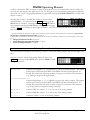
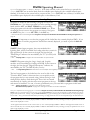
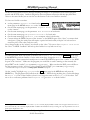
The Back Panel
a) AC Voltage Selector
Line up the dot with the triangle so that your preferred voltage is up. It is absolutely
essential that you select the voltage corresponding to your local AC power!
b) Fuse Holder
A 1-Amp Slow Blow fuse. Always replace it with the correct value.
c) AC Port
Connect an IEC standard 3-prong AC power cord here. The center post is chassis
ground.
S/P DIF Digital Audio Input/Output (Consumer)
S/P DIF is a consumer digital audio standard, with two audio channels encoded into a single connector.
Use these connectors to hook up Orville to CD players, DAT recorders, and other audio gear using this
format. The connectors are two-conductor RCA jacks. Your plug should have the shield connected to the
sleeve with the single shielded conductor connected at the tip.
Eventide recommends the use of professional quality cables made of RG-59/U coaxial cable. Ordinary "hifi" type leads will probably prove inadequate, especially at the higher sample rates.
d) S/P DIF 1/2 output jack
The digital outputs 1/2 are sent out this
jack. Connect this output to the S/P DIF
input on another piece of gear. If the
DOUT 1/2 parameter on the "bottom" format menu page in the SETUP area is set
to S/P DIF, both digital outputs 1/2 (S/P DIF and AES/EBU 1/2) will be in the
"consumer" format. If it's set to AES/EBU, both digital outputs 1/2 will be in the
"professional" format.
e) S/P DIF 1/2 input jack
To select the S/P DIF digital input, set
DIN 1/2 on the inputs menu page in
the SETUP area to S/P DIF.
Page 12
Orville Operating Manual
1999 Eventide Inc.
Manual Release 1.2
Orville Operating Manual
→ See S/P DIF on page 56.
AES/EBU Digital Audio Input/Output (Professional)
Use these connectors to connect professional digital audio gear to Orville. These cables are differential with
a shielded twisted pair. Eventide recommends the use of purpose-manufactured Digital Audio cables, which
have low capacitance and a controlled impedance, for carrying AES signals.
Ordinary microphone cables will usually work at 48kHz, but are likely to reduce range and add jitter and
possible distortion to the signal. It is unlikely that microphone cable will prove satisfactory for 96kHz operation.
f) AES/EBU 1/2 output jack
The digital outputs 1/2 are sent out this
jack. Connect this output to the
AES/EBU input on another piece of
gear. If the DOUT 1/2 parameter on the "bottom" format menu page in the SETUP
area is set to AES/EBU, both digital outputs 1/2 (S/P DIF and AES/EBU 1/2) will
be in the "professional" format. If it's set to S/P DIF, both digital outputs 1/2 will
be in the "consumer" format.
g) AES/EBU 3/4 output jack
The digital outputs 3/4 are sent out this jack. Connect this output to the AES/EBU
input on another piece of gear.
h) AES/EBU 1/2 input jack
If the parameter DIN 1/2 on the inputs
menu page in the SETUP area is set to
AES/EBU, then digital inputs 1/2 are
accepted at this jack. Connect the AES/EBU output of another piece of gear to this
jack .
i) AES/EBU 3/4 input jack
The digital inputs 3/4 are accepted at this jack. Connect the AES/EBU output of
another piece of gear to this jack.
→ See Digital Setup on page 56.
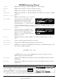
j) Analog Audio Outputs
Orville’s XLR analog audio output jacks are male. Pin #1 is
ground. Pin #2 is +phase (hot) and pin #3 is -phase.
To “unbalance” the jack, use pins #1 and #3 as ground and use
pin #2 as “hot.” If either pins #2 or #3 are unconnected, you
1
2
3
will get more distortion than signal !
The analog outputs 1, 2, 3, and 4 send out signals on their corresponding jacks.
Connect these outputs to the analog inputs of other gear.
Manual Release 1.2
Orville Operating Manual
1999 Eventide Inc.
Page 13
Orville Operating Manual
k) Analog Audio Inputs
Orville’s analog inputs accept either unbalanced 1/4” connectors
or balanced XLR connectors. Orville’s XLR input connectors are
female. Pin #1 is ground. Pin #2 is +phase (hot) and pin #3 is phase.
To “unbalance” the XLR jack, use both pins #1 and #3 as ground
and use pin #2 as “hot.” If either pins #2 or #3 are uncon-
1
2
1/4"
3
nected, you will get more noise and hum than signal !
The analog inputs 1, 2, 3, and 4 accept signals at their corresponding jacks. Connect
the analog outputs of other gear to these jacks. These may be used as both line and
guitar inputs, depending on the input level setting.
→ See Controlling the Level of the Analog and Digital Inputs on page 53.
l) Foot Pedal jacks 1 and 2
Stereo 1/4” connectors. The sleeve is ground reference, the ring is +5 volts
(source), and the tip is an analog signal from 0 to 5 volts. Connect either foot
switches, foot pedals, or control voltage sources to these inputs to modulate parameters or to trigger events (including remote program loads).
→ See Foot Pedals 1 and 2 on page 66.
m) Relay Jack
Two relays are connected to this Stereo 1/4" connector. They can be controlled
from suitable programs, allowing Orville to drive real-world equipment, and can
switch up to 1.0A at 30V dc. Relay #1 is connected between ring and sleeve, while
Relay # 2 is connected between ring and tip. All of these connections are electrically
isolated from Orville. See the separate Programming Manual for information on controlling the relays.
n) MIDI
MIDI is used for instrument to instrument digital communications. Orville sends
and receives Eventide system exclusive messages that allow a MIDI sequencer to remote
control Orville, among other things. In addition, Orville may respond to standard
MIDI messages and may output standard MIDI messages. Orville has three MIDI
ports:
• In - Orville accepts (and processes) MIDI messages received at the MIDI In
port. The connector is “7 pin” and can provide power to a suitable pedal board,
provided you supply power at the “Remote Power In” socket described below. It
can also send MIDI messages from this connector to a suitably equipped system.
This means, for example, that a pedal board can be connected to Orville by
means of a single cable that supplies power as well as a communication path. A
normal "5 pin" MIDI cable can be used as a standard MIDI input.
• Out - Orville sends MIDI messages to other devices via the Out port. MIDI mes•
sages are also sent out the serial port if they are “enabled.”
Thru - Any MIDI information received at the MIDI In port is echoed directly
to the MIDI Thru port regardless of Orville’s configuration (as long as Orville is
powered up) .
With the Memory Card removed, the BUSY LED on the front panel illuminates whenever a MIDI message is received
at the MIDI In port. Note: If the serial port is “enabled” and MIDI is “enabled,” a command received over either the
serial port or the MIDI In port causes the port not receiving the command to be ignored until the command is complete.
Page 14
Orville Operating Manual
1999 Eventide Inc.
Manual Release 1.2
Orville Operating Manual
→ See MIDI Setup on page 67.
o) EveNet ethernet Ethernet jack for use with EveNet proprietary protocol. Visit www.eventide.com for
more information.
p) Serial Port
An IBM PC type RS232 connector that looks like a modem or printer to a connected
computer. Connect a "9 pin" serial cable to this port to transfer information to and
from a personal computer (do not use the "null modem" type of cable designed for
file transfer between two computers - it will not work.) With the Memory Card removed, the
LED on the front panel illuminates whenever a message is received at the serial port. Note: If the serial port is
“enabled” and MIDI is “enabled,” a command received over either the serial port or the MIDI In port causes the port
not receiving the command to be ignored until the command is complete.
BUSY
→ See Setting Up the Serial Port on page 94.
Manual Release 1.2
Orville Operating Manual
1999 Eventide Inc.
Page 15
Orville Operating Manual
GETTING AROUND AND ALTERING PARAMETERS
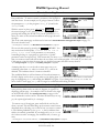
Adjusting the Brightness and Contrast of the Display
Before we begin to describe Orville’s interface, we ought to make sure you can see the display! Adjust the
contrast of the display by pressing the SETUP key until you see
the display SOFT KEY. Press the display SOFT KEY and turn
the KNOB to adjust contrast or press the DOWN CURSOR key
and turn the KNOB to adjust brightness.
The “Areas” of Orville
Orville’s interface is divided into several functional “areas.” You access each area by pressing its key. You’ll
know which area you’re in because the LED next to its key illuminates (except for the BYPASS area, but
that one’s obvious). The areas are:
PROGRAM
Press the PROGRAM key to access this
area. Inside you’ll find utilities for loading
programs, saving programs, deleting
programs, comparing a tweaked program
with the saved version, and creating banks
(“manila folders” for organizing programs). Press the PROGRAM key to access additional SOFT KEYS.
→ See Program Load, Save, Delete, Etc. on page 79.
ROUTING Storage
Press and hold down the PROGRAM key
for one second to access this area. The
LED next to the PROGRAM key blinks.
Here you’ll find utilities for loading,
saving, or deleting “routing configurations.”
→ See Storing and Loading Routing Configurations on page 40.
→ To change the “hold time," see Miscellaneous Setup Options on page 92.
SETUP Storage
Press and hold down the PROGRAM key
again for one second to access this area.
The LED next to the PROGRAM key
blinks. Inside you’ll find utilities for loading, saving, or deleting “routing configurations.”
→ See Storing and Loading Setups on page 92.
→ To change the “hold time," see Miscellaneous Setup Options on page 92.
Page 16
Orville Operating Manual
1999 Eventide Inc.
Manual Release 1.2
Orville Operating Manual
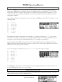
PARAMETER
Press the PARAMETER key to access this
area. Here you’ll find the parameters for
the currently loaded programs. Continue
pressing the PARAMETER key to access
additional SOFT KEYS (if available). → See Parameters on page 88.
The PARAMETER key also gives access to the built-in Patch Editor. Press and hold down the PARAMETER key for one second to
access this area. The LED next to the PARAMETER key blinks.
The Patch Editor allows you to create your own effects from
scratch or to customize programs that already exist.
→ See the separate Programmer’s Manual for more information on the Patch Editor.
→ To change the “hold time," see Miscellaneous Setup Options on page 92.
LEVELS
Press the LEVELS key to access this area.
Inside you’ll find level and Level Meter parameters.
→ See Controlling Levels on page 51.
SETUP
Press the SETUP key to access this global,
“catch-all” area. Inside you’ll find routing
parameters, digital setup controls, global
MIDI setup, global “external” setup,
display contrast/brightness, the pedal jacks’ setup, dump data utilities, next/previous
program advance, and miscellaneous service utilities. Press the SETUP key more than
once to access additional SOFT KEYS.
BYPASS
Press SYSTEM BYPASS to access this area.
Inside you’ll find the bypass options and
the SOFT KEYS used to actually bypass or
“un”-bypass.
→ See Bypassing and Muting on page 64.
Manual Release 1.2
Orville Operating Manual
1999 Eventide Inc.
Page 17
Orville Operating Manual
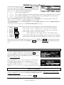
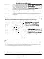
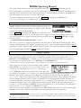
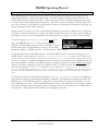
Understanding the Display and SOFT KEYS
Every “area” in Orville makes use of the display, so understanding the display is critical. A generic screen of
the sort typically found in the PARAMETER area is shown below. It exemplifies various aspects of the dis-
play that remain constant no matter what area of Orville you’re in.
First, in the upper left-hand corner of the display is either the letter “A” or the
letter “B.” This is the “DSP Display Indicator.” If it reads “A,” then everything
else on a “DSP sensitive” screen is in reference to DSP A. If it reads “B,” then
everything else on a “DSP sensitive” display is in reference to DSP B. Press the
DSP A/B key to toggle the display between the two DSPs. The screens in the
PROGRAM, PARAMETER, and Patch Editor are “DSP sensitive." Both DSPs are always running, but the
display only shows the parameters for one of them at a time. The “DSP Display Indicator” lets you know which one you’re fiddling with. Look to it
often.
The remainder of the upper left-hand corner of the display always shows the name of the program currently
running on the DSP referred to by the “DSP Display Indicator.” In the example shown above, we’re running a program “Quad Flange Echo” on DSP A. The upper right-hand corner of the display always describes the menu page you’re looking at. In the example shown above, we’re looking at the “delay mod”
menu page.
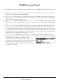
Situated along the bottom of the display are the so-called “SOFT KEYS.” The four physical keys located
below the display select menu pages or events corresponding to these SOFT KEYS. (They’re called “soft”
because their function changes depending on context.) The “More Soft Keys” indicators are the little arrows next to the SOFT KEYS shown above. They indicate that if you press the “area” key you used to access the current display again, you will access more SOFT KEYS. The arrows are meant to imply that more
pages exist in a nether-world beyond the display. . .
For example, press the SETUP key to see the “More Soft Keys”
Page 18
Orville Operating Manual
1999 Eventide Inc.
Manual Release 1.2
indicators.
Orville Operating Manual
Press the SETUP key again to get more SOFT KEYS.
Press the SETUP key until you return to the original set of SOFT
KEYS.
A “Stacked” SOFT KEY (shown above) indicates that if you repeatedly press the “stacked” SOFT KEY, you
will access more menus. The graphic is meant to imply that there are more pages lying “below” the “top”
one.
For example, repeatedly press the SETUP key until you see the
stacked SOFT KEY midi . Press midi .
Press it again to get a second menu page.
Press it again to get a third menu page.
Press it until you return to the original menu page.
Pressing a SOFT KEY repeatedly that is not stacked puts Orville into “self destruct” mode. Just kidding. It
has no effect.
When you press a SOFT KEY, it becomes highlighted. The middle section of the screen is a menu page corresponding to that highlighted SOFT KEY. Use the cursor keys to “move around” on the menu page. Use
the KNOB, the NUMERIC KEYPAD, and the SELECT key to change and enter values.
→ See Using the Cursor Keys, the SELECT key, the NUMERIC KEYPAD, and the KNOB on page 20.
Before moving on, we ought to say that not all SOFT KEYS are menu pages. Some SOFT KEYS are “triggers.” A “trigger” is a key that triggers an event, get it? You’ll always know the difference between menu
page SOFT KEYS and trigger SOFT KEYS because menu page SOFT KEYS are rectangular, whereas trigger
SOFT KEYS are hexagonal. On this screen Operate and About are menu pages, and <Bong> and
<Throttle> are triggers.
Manual Release 1.2
Orville Operating Manual
1999 Eventide Inc.
Page 19
Orville Operating Manual
Using the Cursor Keys, the SELECT key, the NUMERIC KEYPAD, and the KNOB
We use the CURSOR keys, the KNOB, the SELECT key, and the NUMERIC KEYPAD to navigate and manipulate the menu pages found in the PARAMETER, Patch Editor, LEVELS, BYPASS, and SETUP areas. We’ll
discuss their use in the PROGRAM and Routing Storage areas in a bit.
Use of the cursor keys is straightforward. The LEFT and RIGHT CURSOR keys move the cursor left and
right, respectively. If you move the cursor “past the edge of the screen," it will “wrap” around to the other
side. The UP and DOWN CURSOR keys move the cursor up and down, respectively. Again, the top and
bottom “wrap” around.
Use the KNOB, NUMERIC KEYPAD, or the INC/DEC keys to alter the
value of a numeric parameter. For example, spin the KNOB on this
screen to change the value of Mix or enter a new value directly with
the NUMERIC KEYPAD (pressing ENT when you’re done). If you
accidentally enter the same value for the parameter with the NUMERIC KEYPAD as was
already there, ENT will have no effect. To “escape” from this situation, repress the SOFT KEY
for the current menu or move the cursor. For example, if you type 50 for Mix in the above
screen, ENT will have no effect. Press [PHASE] again or move the cursor to “escape.”
To get to a screen like this one, first press the PROGRAM
key. Scroll through the banks (using the LEFT or RIGHT
CURSOR keys) to “PHASERS." Scroll through the
programs in that bank to “StereoizingPhaser."
Load it and press the PARAMETER key.
Use the KNOB or the INC/DEC keys to alter the value of a text
parameter. For example, spin the KNOB or press the INC key to
change Shape from Sine to Triangle on this screen.
Numeric parameters and text parameters cover 99% of the parameters you’ll see in Orville, but there are a few more esoteric parameters you’ll encounter. One such oddball is the “trigger” parameter.
Remember, “triggers” trigger things to happen. You place the cursor over a trigger parameter, and trigger it by pressing SELECT. Other oddballs include “Taps” and
“Graphics.”
→ See Graphics and Curves on page 90.
Ganged Parameters
In some cases there are multiple, related parameters that are usually adjusted together. To make such “mass
adjustments” easy, a feature exists that gangs parameters together.
The outputs menu page in the SETUP area contains a good
example of ganged parameters. The purpose of this menu page is
to assign signals to the outputs. Such assignments are typically
made in quad or stereo gangs. So, all four parameters are initially ganged together. Spin the KNOB and all
four values change.
Now let’s say you only want to change ANA1 and ANA2. Press the
DOWN CURSOR key to “ungang” ANA3 and ANA4. Now spin the
KNOB; only the values for ANA1 and ANA2 change.
Page 20
Orville Operating Manual
1999 Eventide Inc.
Manual Release 1.2
Orville Operating Manual
Going further, let’s say you only want to change the value of
ANA1. Again, press the DOWN CURSOR key to “ungang” ANA2.
Now spin the KNOB; only the value of ANA1 changes. Press the
DOWN CURSOR key to repeatedly cycle through the various gang
possibilities: next ANA2 alone is selected, then ANA3 and ANA4 are ganged together, then ANA3 is alone, then
ANA4 is alone, and lastly we arrive at our starting point - all four parameters are ganged together. Gangs are
much easier to use than to describe, so take a minute and play with the gangs on this menu page. You will
find gangs sprinkled liberally throughout Orville as their presence facilitates many tasks.
Using the Cursor Keys and the KNOB in the PROGRAM and Routing Storage Areas
Now, let’s investigate the use of the cursor keys and the KNOB in
the PROGRAM area (they work just the same in the Routing Storage area). Things
are only a little bit different here than in the other areas. The box
on the display with the word “banks” in it is called the “bank
field.” The box below the banks field with the word “programs”
in it is called the “programs field.” In the PROGRAM area, the UP and DOWN CURSOR keys scroll through
programs and the LEFT and RIGHT CURSOR keys scroll through banks (banks are “manila folders” for programs. See Banks on page 79). The SELECT key, the <load> SOFT KEY, and the ENT key all load the program
shown in the display with the triangle next to its number (you may need to press the PROGRAM key again to find the <load>
SOFT KEY). For example:
Press either the LEFT or RIGHT CURSOR key when the cursor is in
the programs field (as on the above screen) to position the cursor
over the bank field (as shown to the right).
With the cursor in the bank field, press the LEFT or RIGHT
CURSOR key to scroll through banks. Spinning the KNOB also
scrolls through banks. Pressing the RIGHT CURSOR key three
times on the above screen would scroll through banks and result in
the screen to the right.
Press the UP or DOWN CURSOR key when the cursor is in the
bank field (as on the above screen) to move the cursor to the programs field (as shown to the right).
Manual Release 1.2
Orville Operating Manual
1999 Eventide Inc.
Page 21
Orville Operating Manual
With the cursor in the programs field, press the UP or DOWN
CURSOR key to scroll through programs. Spinning the KNOB also
scrolls through programs. Pressing the DOWN CURSOR key twice
on the above screen would scroll through programs and result in
this screen.
Page 22
Orville Operating Manual
1999 Eventide Inc.
Manual Release 1.2
Orville Operating Manual
Press the SELECT key, the <load> SOFT KEY, or the ENT key to
load the program shown in the display with a triangle next to its
number. On the above screen “12 Compressor_Q” has the triangle next to its number.
Pressing SELECT, <load>, or ENT would load “Compressor_Q” and result in this screen. Notice that the
upper left-hand corner of the display reflects the fact that “Compressor_Q” is now the current program
running on DSP A.
The moral of the story? Use the LEFT and RIGHT CURSOR keys to scroll to the bank from which you want
to load a program. Then use the UP and DOWN CURSOR keys to scroll through programs to the particular
program you want to load. When you get there, press the SELECT key, the <load> SOFT KEY, or the ENT
key.
→ To learn how to remotely load programs, read Loading a Program Remotely on page 82.
Entering or Changing Text
In some menus, it will be necessary to enter or change text. For
example, you will often change text when saving a new program.
The method by which this is done is straightforward, albeit a bit
tedious. To play along, go to the PROGRAM area and press the <save> SOFT KEY.
(You may have to press the PROGRAM key a second time to see it.) Press the UP CURSOR key twice, so that the box next to “name” is highlighted
and press the SELECT key. To escape from this “pop-up” menu, highlight the “cancel” box and press the SELECT key.
Here’s how it works: Select the item that has the text you want to add or change (with the cursor keys) and
press the SELECT key. Now the LEFT and RIGHT CURSOR keys move you through the text string and the
CXL key acts as a backspace key, deleting characters as it moves back. Turn the KNOB to scroll through alphanumeric characters. When you arrive at the character you want, stop scrolling and move the cursor past
that character. Begin scrolling again for the next character. When you are finished entering your text, press
the SELECT key or the ENT key to make it “stick.” The list of alphanumeric characters in order is:
; : / ? > < , ; ` ~ | \ _ = + - } { ] [ ‘ ) ( * & ^ % $ # @ ! z y x w v u t s r q p o n m l k j i h g f e d c b a space
ABCDEFGHIJKLMNOPQRSTUVWXYZ0123456789.-%
Manual Release 1.2
Orville Operating Manual
1999 Eventide Inc.
Page 23
Orville Operating Manual
QUICKSTART OR “NEARLY INSTANT GRATIFICATION”
All right, all right! Areas, displays, SOFT KEYS, parameter this, scroll that. . . BUT WHAT CAN IT DO?
Let’s cut to the chase and get you up and running! Besides, if you played with the box a good deal before
moving on to the finer points of operation, those finer points will stick better to the ol’ gray matter. . .
Here are the steps we will take:
1. First, we’ll connect Orville to the rest of your gear.
2. On page 26 we’ll route signals between all of those inputs, outputs, and DSPs you’ve been reading so
much about.
3. On page 29 we’ll set the input levels so that things don’t distort.
4. On page 30 we’ll learn how to “mute” Orville in the event of feedback.
5. On page 32 we’ll run programs on DSP A and DSP B and “tweak” their parameters.
6. Finally, on page 34 we’ll learn how to save the programs you’ve “tweaked” for future use.
Hooking Up
Before we concentrate on what happens inside Orville, we ought to get it hooked up to the rest of your studio. As was stated in the overview, we have four analog inputs, four analog outputs, four digital inputs, and
four digital outputs all at our disposal all the time.
→ See The Back Panel on page 12 for information on the jack types and their specifications.
Hook up the analog inputs to suitable output sources, such as an analog mixer’s effect sends or the outputs
of a preamplifier. You may want to split up the four analog inputs. For example, you could connect two
effects sends to analog inputs 1 and 2 and the output of a stereo preamplifier to analog inputs 3 and 4. The
connections may be made with either balanced XLR connectors or unbalanced 1/4” connectors. You can
plug a guitar into the 1/4" jacks, but you will need to turn up the input gain.
→ See Setting Input Levels on page 29.
Hook up the balanced analog outputs to suitable input recipients, such as an analog mixer or an amplifier.
As with the analog inputs, you may wish to split up the four analog outputs.
Hook up the digital inputs to suitable output sources, such as a DAW (digital audio workstation) or a keyboard with digital outputs. Unlike the analog interface, the sources of your digital signals must come in
pairs. Further, digital inputs 1 and 2 are taken from either the AES/EBU 1/2 input jack or the S/P DIF
1/2 input jack (see below to learn how to switch between the two). Digital inputs 3 and 4 are necessarily
taken from the AES/EBU 3/4 input jack.
Hook up the digital outputs to suitable input recipients, such as a DAW, a sampler, or a DAT machine. As
with the digital inputs, the recipients of your digital signals must come in pairs. Further, digital outputs 1
and 2 are sent from either the AES/EBU 1/2 output jack or the S/P DIF 1/2 output jack (see below to
learn how to switch between the two). Digital outputs 3 and 4 are necessarily sent from the AES/EBU 3/4
output jack.
Note: You don’t have to hook up all 16 inputs and outputs! Just be mindful of which are hooked up and
which aren’t when we get to routing, below.
Page 24
Orville Operating Manual
1999 Eventide Inc.
Manual Release 1.2
Orville Operating Manual
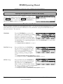
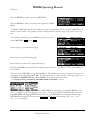
To make sure we aren’t stopped before we start, go to the clock
menu page in the SETUP area (you may have to press the SETUP key a few
times to find it). If you aren’t using the digital inputs, set the Source
parameter to Int 48.0 kHz as shown to the right (using the
CURSOR keys and the KNOB).
If you are using the digital inputs, set the parameter Source to
AES/EBU 1/2 or S/P DIF 1/2 (depending on which you've selected as the
digital input; see the paragraph below). Orville will derive its sampling rate
from digital inputs 1/2.
Digital inputs 1/2 are “taken” from either the AES/EBU 1/2
input jack or the S/P DIF 1/2 input jack. Select one or the other
with the parameter IN 1/2 on the inputs menu page. If you
are only using two digital inputs, you must connect them to
digital inputs 1/2 (either the AES/EBU input or the S/P DIF input).
If digital inputs 3/4 aren't synchronized to inputs 1/2 at the
source, use the sample rate converter. Turn SRC Mode 3/4 to
on. In the example shown to the right, digital inputs 3/4 will be
sample rate converted to the sample rate of digital inputs 1/2,
48000 Hz.
Digital outputs 1/2 are “sent” to both the AES/EBU 1/2 output
jack and the S/P DIF 1/2 output jack, but they can only be sent
in one format, "consumer" or "professional". Select S/P DIF on
the "bottom" format menu page in the SETUP area to select the
"consumer" format; select AES/EBU to select the "professional" format.
Digital inputs and outputs 3 and 4 must be “taken” from the AES/EBU 3/4 input jack and “sent” to the
AES/EBU 3/4 output jack. This is because there is no S/P DIF 3/4 jack.
→ To read about the digital setup in more detail, see Digital Setup on page 56.
Manual Release 1.2
Orville Operating Manual
1999 Eventide Inc.
Page 25
Orville Operating Manual
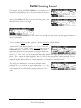
Loading Routing Configurations
As was stated in the overview, Orville houses two separate DSP engines. DSP A is always running a program, and DSP B is always running another program. The program running on DSP A does not necessarily
have anything to do with the program running on DSP B, and the program running on DSP B does not
necessarily have anything to do with the program running on DSP A! (The display can only show the parameters for one of them at a time - use the DSP A/B key to toggle between displays.)
While functioning of DSP A is quite independent of DSP B and vice versa, we can route signals between
them. Each DSP can accept four input signals and produce four output signals. What’s more, Orville is
equipped with four analog inputs, four analog outputs, four digital inputs, and four digital outputs. All of
these inputs and outputs can be used simultaneously. The signal routing between the various ins and outs and
the two DSPs is comprehensive and can be manually configured in just about any way imaginable. However, for the purposes of this “Instant Gratification” section, we’ll stick to the routing configurations that
come as presets in Orville. (Besides, you’ll probably use these preset configurations most of the time because they cover the most obvious and necessary routing configurations.)
→ To learn how to manually configure the routing configuration, see Signal Flow Inside Orville on page 38.
To access the preset routing configurations, press and hold down
the PROGRAM key for one second to enter the Routing Storage
area. The LED next to the PROGRAM key will begin to blink and
the upper right-hand corner of the display will read “routing.”
Use the UP and DOWN CURSOR keys to place the cursor over
the routing configuration you would like to load and then press the <load> SOFT KEY. Below, we describe
each preset routing configuration in English and complement that description with a block diagram. The
routing configuration “name” as saved in Orville follows each description.
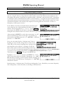
→ To change the “one second hold time," see Miscellaneous Setup Options on page 92.
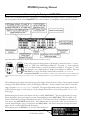
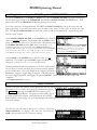
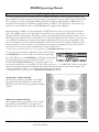
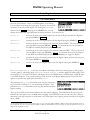
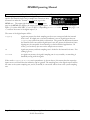
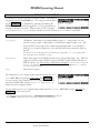
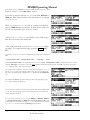
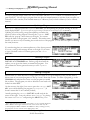
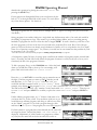
“Analog A->B” - Analog Serial Quad
All four analog inputs go into DSP A, the output
from DSP A goes into DSP B, the output from
DSP B goes into both the analog outputs the digital
outputs.
“Digital A->B” - Digital Serial Quad
All four digital inputs go into DSP A. The outputs
from DSP A go into DSP B, the outputs from
DSP B go into both the analog and digital outputs.
Page 26
Orville Operating Manual
1999 Eventide Inc.
Manual Release 1.2
Orville Operating Manual
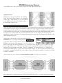
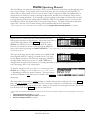
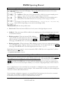
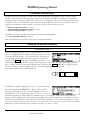
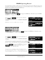
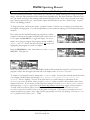
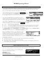
“Eight Track A,B” - Eight Track 1
All four analog inputs go into DSP A, out from
DSP A into the analog outputs. All four digital
inputs go into DSP B, out from DSP B into the
digital outputs.
“Eight Track B,A” - Eight Track 2
All four analog inputs go into DSP B, out from
DSP B into the analog outputs. All four digital
inputs go into DSP A, out from DSP A into the
digital outputs.
“Analog A || B” - Analog Parallel Quad
All four analog inputs go into DSP A and DSP B,
all four outputs from both DSP A and DSP B are
summed at the analog outputs and the digital
outputs.
“Digital A || B” - Digital Parallel Quad
All four digital inputs go into DSP A and DSP B, all
four outputs from both DSP A and DSP B are
summed at the analog outputs and the digital
outputs.
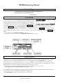
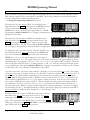
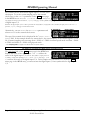
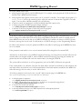
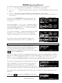
“Analog Dual Stereo”
Analog inputs 1 & 2 go into DSP A 1 & 2, DSP A
outs 1 & 2 go into analog outputs 1 & 2 and digital
outputs 1 & 2. Analog inputs 3 & 4 go into DSP B
Manual Release 1.2
Orville Operating Manual
1999 Eventide Inc.
Page 27
Orville Operating Manual
1 & 2, DSP B outs 1 & 2 go into analog outputs 3 & 4 and digital outputs 3 & 4.
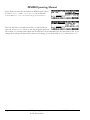
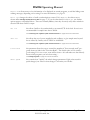
“Digital Dual Stereo”
Digital inputs 1 & 2 go into DSP A 1 & 2, DSP A
outs 1 & 2 go into analog outputs 1 & 2 and digital
outputs 1 & 2. Digital inputs 3 & 4 go into DSP B
1 & 2, DSP B outs 1 & 2 go into analog outputs 3
& 4 and digital outputs 3 & 4.
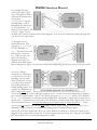
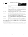
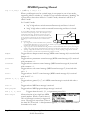
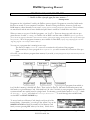
The I/O Identifier
While each DSP has four inputs and four outputs, it’s not necessarily the case that every program will utilize
all four inputs or all four outputs of the DSP it’s running on. Every program is unique and uses only the
number of inputs and outputs that are necessary for its function. For instance, a program that synthesized
sound would not need any inputs! A program that modulated one stereo signal with another would need all
four inputs (two for the carrier and two for the modulator) but only two outputs (for the result of the
modulation). Again, the function of a program determines how many inputs and outputs are utilized on the
DSP running the program.
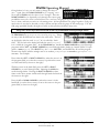
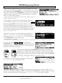
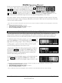
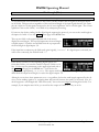
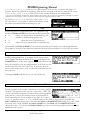
Notice that to the far right of every program name in the
PROGRAM area is a two digit number (press the P
P
R
O
G
R
A
M
PR
RO
OG
GR
RA
AM
M key
to get there). This two digit number is known as the “I/O
Identifier.” In the case of the program “IntervalicShift_Q”
shown to the right, the two digit number is “44.” In the case of the program “H910s” shown to the right,
the two digit number is “22.” The first digit indicates how many inputs are utilized, and the second digit
indicates how many outputs are utilized. If the “I/O Identifier” for a program were “13,” DSP input 1
would be used while inputs 2, 3, and 4 were dead, and DSP outputs 1, 2, and 3 would be used while output
4 was dead. A program will utilize the same number of inputs and outputs regardless of whether it is loaded
on DSP A or DSP B.
→Some programs have no I/O identifier. See If the I/O Identifier is not visible on page 48 for more information.
Those DSP inputs or outputs that are not used by the program are “dead” - no signals are passed by them.
Page 28
Orville Operating Manual
1999 Eventide Inc.
Manual Release 1.2
Orville Operating Manual
Knowing which inputs and outputs a program uses can affect which routing configuration you choose to
use. You probably wouldn’t want to place a program that only utilized two inputs after a program that utilized all four outputs because two of those outputs would be connected to “dead” inputs. (Of course, it wouldn’t
hurt anything if you did, but the signals at the two outputs connected to “dead” inputs would be “lost.") This scenario is depicted in the
diagram above.
It’s important for you to think about which inputs and which outputs from DSP A and DSP B are “dead” in
the context of the routing configuration you’ve chosen.
→ For more information on this topic, including examples, see Programs’ Effect on Routing Decisions on page 48.
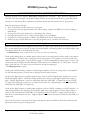
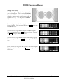
Setting Input Levels
As we’re sure you know, getting a high, but not distorted, signal at
every point in a signal path is essential. The Level Meters help us
to achieve this goal. In the LEVELS area go to the meter menu
page to reach this screen. Adjust Source (with the KNOB or the
INC/DEC keys) to read either analog in or digital in depending on which input levels you would like to view. The four Level Meters now reflect either the four analog
inputs or the four digital inputs.
In this cursory introduction, we only fiddle with the levels at the
inputs but, rest assured, you can change levels anywhere in the
signal path.
→ See:
•
Controlling the Level of the Analog and Digital Inputs on page 53.
•
Input Levels, Wet/Dry Ratios, and Output Levels for Each DSP on page 54.
•
Controlling the Level of the Analog and Digital Outputs on page 55.
Of course, it’s always best to optimize levels at their source (leaving Orville’s boost/cut at 0dB). But if you
can’t, then go to the inputs menu page in the LEVELS area. Press it twice so that only the analog input
levels are shown. Here you can boost/cut the analog inputs by +30dB/-90dB before they are digitally converted.
You can cut the analog inputs after digital conversion and the
digital inputs by 0db/-100dB on the first inputs page.
Assuming you set the Source of the Level Meters to analog in
or digital in on the meter menu page in the LEVELS area,
the meters reflect the input levels (after the boost/cut is applied). You want the loudest portions of the signal to approach, but not reach, the red “clip” LED at the top of the Level Meters. If you do clip a signal,
you won’t hurt Orville, but you will hurt your chances for career advancement - a clipped signal typically
sounds nasty.
→ For more information on setting input levels see Controlling the Level of the Analog and Digital Inputs on page 53.
Manual Release 1.2
Orville Operating Manual
1999 Eventide Inc.
Page 29
Orville Operating Manual
Effecting Things
“The effect on your affect of Orville’s effects will
positively affect your popularity.”
-Anonymous
“Panic” Muting
In a moment you’ll be loading and playing with programs, but before you do let it be said that Orville can produce LOUD sounds
with very little warning in some of the programs in some situations.
It would be nice to have a “panic” key to press in such a situation.
Let’s arrange things so that pressing and holding the B
B
Y
P
A
S
S
BY
YP
PA
AS
SS
S key for one second mutes all of Orville’s outputs.
Go to the options menu in the BYPASS area. Change the value of the system parameter to mute as
shown above (with the KNOB or the INC/DEC keys). Now hold down the B
B
Y
P
A
S
S
BY
YP
PA
AS
SS
S key. After a second
the A and B LEDs begin to blink - you’ve muted Orville. To unmute, simply hold down the B
B
Y
P
A
S
S
BY
YP
PA
AS
SS
S key
again.
→ For more information see Bypassing and Muting on page 64.
→ To change the “one second hold time," see Miscellaneous Setup Options on page 92.
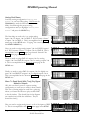
Loading Programs
Assuming you’ve loaded an appropriate routing configuration, Orville should be ready to process! All that
remains is to load a program into each DSP. To load a program, enter the PROGRAM area. You’ll see a
box that says “banks” and a box that says “programs.” Banks are “manila folders” for programs; many
programs with a common theme are saved in a single bank. There can be as many as 100 bank “slots” in the
internal memory of Orville, and each bank contains 128 program “slots.”
The number of program “slots” that can actually “contain” programs is limited to the amount of storage space available.
→ See The “Size” of a Program and Its Ramifications for Storage on page 80.
The "Speed" indicator (slightly like a lightning symbol) indicates that this program can be loaded and run in
high speed mode, for use at 88.2kHz and 96kHz sampling rates.
→ See Sampling Rates on page 57 for more information on speed modes.
Page 30
Orville Operating Manual
1999 Eventide Inc.
Manual Release 1.2
Orville Operating Manual
Use the LEFT and RIGHT CURSOR keys to scroll through banks and the UP and DOWN CURSOR keys to
scroll through programs. Use the S
S
E
L
E
C
T
E
N
T
SE
EL
LE
EC
CT
T key, the <load> SOFT KEY, or the E
EN
NT
T key to load the highlighted program.
→ For the finer nuances of PROGRAM area navigation read Using the Cursor Keys and the KNOB in the PROGRAM and Routing
Storage Areas on page 21.
When you highlight a program you want to load into the currently displayed
DSP (referred to by the letter in the upper left-hand corner of the screen), press
the S
S
E
L
E
C
T
SE
EL
LE
EC
CT
T key. If you want to load the program into the DSP not
currently displayed, press the D
D
S
P
A
B
DS
SP
PA
A///B
B key. Doing so will toggle the display
to the other DSP.
Let’s load some programs,
shall we?
Pressing the S
S
E
L
E
C
T
SE
EL
LE
EC
CT
T key on the screen above would load the
program “Bigger is Wider” into DSP A. Notice that the
upper left-hand corner of the display reflects the fact that
“Bigger is Wider” is loaded on DSP A on the screen to the
right.
Pressing the D
D
S
P
A
B
DS
SP
PA
A///B
B key would toggle the display so that we
could load a program into DSP B.
Scrolling through banks and programs would do good things for
our hand-eye coordination.
Pressing S
S
E
L
E
C
T
SE
EL
LE
EC
CT
T on the screen above would load the program
“ChorusDelays” into DSP B. Notice that the upper left-hand
corner of the display reflects the fact that “ChorusDelays” is
loaded on DSP B on the screen to the right.
Note that many of the programs in the "Inst" series are
designed so that a foot pedal connected to the foot pedal jack will
control the output volume. If you don't have a foot pedal hooked
up, go to the external menu page in the SETUP area (you may
have to press SETUP a few times to see it). Making sure that the
upper right corner of the screen reads "assign 1 setup" and
change mode to high. This will allow you to hear these programs!
→ See Foot Pedals 1 and 2 on page 66 and The Concept Behind “Redirection” - External Assigns 1-8 and Trigs 1 &2 on page 79
Manual Release 1.2
Orville Operating Manual
1999 Eventide Inc.
Page 31
Orville Operating Manual
Parameters
Simply loading programs probably won’t prove satisfying for too long;
you’ll want to mess with the parameters on the programs you load. This
is accomplished in the PARAMETER area. Very little can be said generally
about what you’ll find in the PARAMETER area because every program in
Orville is a unique “algorithm.” Each unique algorithm (i.e., program)
calls for its own unique parameters.
→ To learn more about the “algorithmic” nature of Orville’s programs, read the
separate Programmer’s Manual.
A huge number of Orville's LFO's, delay times, reverb decays,
etc. are designed to synch to an system tempo defined on the tempo
menu page in the SETUP area. Say you're working on a song
that’s at 130 BPM. Simply set the system tempo to 130 and most
of Orville's LFO's and delay times will be appropriate for the
song. No more calculators. You can also derive the system tempo
from a midiclock signal applied to Orville's MIDI input. Simply
set Source to Midiclock.
Parameters that synch to the system tempo are identified by "t_"
such as "t_rate" and "t_fmrate" and are adjusted in musical
terms such as "whole note" and "dot 1/8". You will find them
in the PARAMETER area of most programs.
→ See System Tempo on page 88
→ Some parameters, such as delay loops, use the system timer. They are also denoted by "t_". See System Timer on page 89
You will usually find an info or about menu page in the
PARAMETER area. In it, you will find general information about
what the program does along with any notes concerning special
parameters or “nonobvious things.”
The parameters displayed in the PARAMETER area pertain to the program
running on the currently displayed DSP (referred to by the letter in the upper
left-hand corner of the screen). If you would like to fiddle with the parameters
for the program running on the DSP not currently displayed, press the DSP A/B
key. Doing so will toggle the display to the DSP you want.
For example, here we’re adjusting parameters for the program
“4*6 Grafic Eq” that is loaded on DSP A.
Pressing the DSP A/B key toggles the display from parameters for the program running on DSP A to parameters for the program running on DSP B. After pressing the DSP A/B key, we get the screen to the right.
Now we can adjust parameters for the program “4_Interval Shift” that is loaded on DSP B.
Page 32
Orville Operating Manual
1999 Eventide Inc.
Manual Release 1.2
Orville Operating Manual
Many, but by no means all, of the programs in Orville currently
support an "expert mode” feature. The expert mode parameter
controlling this feature is found on the misc menu page in the
SETUP area (you may have to press the S
S
E
T
U
P
SE
ET
TU
UP
P key a few times
to find it). A setting of 0 hides all but the most relevant menu
pages in the PARAMETER area. Conversely, a setting of 9 reveals all of the available menu pages in the
PARAMETER area. Settings between 0 and 9 reveal an increasing number of menu pages in the
PARAMETER area.
Leave expert mode at 9 if you like lots of parameters to tinker with, at 0 if you find lots of parameters annoying, or somewhere in-between if your tastes fall somewhere in-between.
→ See Miscellaneous Setup Options on page 92 for information on the other keys on this screen.
It should also be mentioned that any parameter on any menu page can be “remote controlled” via MIDI or
the rear foot pedal jacks. Telling you how to do this entails discussing voluminous topics such as setting up
MIDI globals, setting up foot pedal globals, and navigating a “remote control” menu page. Such a discussion wouldn’t be in keeping with the concept of this Quickstart section.
→ If this really piques your interest, go ahead and read:
Setting Up the External Controllers on page 66.
External Modulation and Trigger Menu Pages on page 70.
Remote Controlling Parameters on page 83.
Manual Release 1.2
Orville Operating Manual
1999 Eventide Inc.
Page 33
Orville Operating Manual
“Tweaking” and Saving “Tweaks”
Different sets of parameter values for a single program are said to be different “tweaks” of that program.
As you play with the parameters on the preset programs, you are “tweaking” those preset programs. For
instance, let’s say you want a program that mimics the frequency response of your neighbor’s television as
heard through your wall. You want to “tweak” the parameters of a filter program in order to get the correct
frequency response.
First, load the program “Filter_Q” from the “Basics” bank.
Do some long calculations involving transmission coefficients
and dispersion laws to arrive at the proper filter cutoff frequency
and resonance. Enter them.
To avoid going through all of the arduous math the next time you
want to mimic the frequency response of your neighbor’s
television, you should save your tweaks as a new program. Press
the PROGRAM key to enter the program area.
Press the <save> SOFT KEY. You’ll see a pop-up menu with a
few options.
The “bank” line allows you to select which bank in which you
will save the program.
The “program number” line allows you to change which number
“slot” you save the program in. Your choices will be all those numbers between 0 and 127 that do not already have a program assigned to them (including the presets!).
By placing the cursor over the “name” line and pressing the SELECT key, you can change the name of the
program. Once you’ve picked a bank, a program number, and a name, place the cursor over the “save” line
and press SELECT to go ahead with the save (place the cursor over “cancel” and press SELECT to abort).
→ See Banks on page 79.
→ To learn how to enter text, see Entering or Changing Text on page 23.
If you were to change the “bank” to “PX-Communication," the
“program number” to “36," and the “name” to “Irritating
TV,” the screen would look like this.
After selecting save, the screen changes to confirm that the program is now saved in the correct bank and in the correct program
“slot.” Now you can load your tweak and feel edgy and irritated even when the neighbors
are on vacation!
→ To read about using Memory Cards, see Memory Cards on page 36.
→ To update a program you have already saved, see Updating a Program on page 84.
→ To link programs from different banks (for ease of loading in, say, a live situation), see “Linking” Programs on page 85.
→ To compare your tweaks with the saved version of a program, see Comparing a Currently Loaded Program With The Original
(Saved) Version on page 87.
Page 34
Orville Operating Manual
1999 Eventide Inc.
Manual Release 1.2
Orville Operating Manual
Wrap Up
So, there you have it. The procedure we followed in this Quickstart section is more or less the procedure
you will follow whenever you use Orville. First, you will determine an appropriate routing configuration for
the task at hand and either load it from the Routing area or make it from scratch (you’ll learn how in the
Operation guide). Then, you’ll load appropriate programs into DSP A and DSP B being mindful of the
“I/O Identifiers” and their bearing on the routing configuration. This may be an over-simplification! You may very well
select appropriate programs for the task at hand and then determine an appropriate routing configuration for those programs! Once the routing
configuration is set and the programs are loaded, you’ll probably “tweak” the parameters on those programs
to fit the situation. When you’re done using a program, you'll probably save your “tweak” for future use.
Doing this much will give you an appreciation of the horsepower under the hood of Orville. But only doing
this much won’t give you an appreciation of the amazing versatility of Orville:
•
In addition to simply loading routing configurations, you can manually configure things any way you
like.
→ See Signal Flow Inside Orville on page 38.
•
In addition to altering levels at the inputs, you can alter and monitor levels at any point in the signal
path.
→ See Controlling Levels on page 51.
•
Programs and routing configurations can be saved to and loaded from removable Memory Cards, as
well as internal memory.
→ See Memory Cards on page 36.
•
In addition to using system bypass, DSP A and DSP B can be muted or bypassed independently of each
other.
→ See Bypassing and Muting on page 64.
•
In addition to loading programs from the front panel, programs can be loaded remotely via MIDI program change messages or external “triggers."
→ See Loading a Program Remotely on page 82.
•
The digital inputs and outputs have comprehensive sample rate and word length parameters to complement any digital installation.
→ See Digital Setup on page 56.
•
Any program anywhere in Orville can be “remote controlled” via MIDI or the rear panel foot pedal
jacks 1 and 2.
→ See Setting Up the External Controllers on page 66, External Modulation and Trigger Menu Pages on page 70, and Remote
Controlling Parameters on page 83.
•
Existing programs can be altered or entirely new programs can be created in the Patch Editor.
→ See the separate Programmer’s Manual.
Manual Release 1.2
Orville Operating Manual
1999 Eventide Inc.
Page 35
Orville Operating Manual
OPERATION
Mounting and Handling
Normally, Orville will be rack mounted in a standard 19 inch rack. If the rack will be taken on the road,
Orville should be supported at the rear. It is advisable to keep the rack well ventilated and in a dry, dustfree environment, so that heat and moisture won’t cause degradation of performance. Contrary to some
reports, we have found that soda/beer splashed liberally about the front panel does not enhance the reliability of Orville. Since Orville has few internal connectors, it should hold up well under “road conditions.”
Memory Cards
All functions that work on internal user memory also work on Memory Cards. A standard Memory Card is
524,288 bytes (1/2 a megabyte), although Orville will support cards up to 4,194,304 bytes (4 megabytes).
(Note: Memory Cards must be “PCMCIA type 1 static RAM card” - Orville does not support "Flash" cards.)
A Memory Card will not maintain memory if the battery dies or if the battery is removed. To change the
battery without losing information, change it while it's plugged into a powered-up Harmonizer. A conservative estimate puts the lifetime of a battery at a year. . . Like gambling on the stock market, bet only what you
can afford to lose. . .
Insert a Memory Card by pushing it into its slot until it “locks” into place. The Memory Card Release will
“lengthen,” and the display will briefly read Checking “Memory Card". . or Checking “GTR Library”. . or (generally) Checking “whatever-the-name-of-this-card-is”. . .
Remove a Memory Card by pressing the Memory Card Release - but don’t remove a Memory Card when
the BUSY LED is lit! A program that was loaded from a Memory Card continues to run even if the Memory Card is subsequently removed. The Memory Card only needs to be in place during PROGRAM and
Routing Storage area functions such as <load>, <save>, <update>, <delete>, etc. The BUSY LED is used to
indicate that a Memory Card is being written to. However, if there is no Memory Card in place, the BUSY LED indicates data at the MIDI In port
or the serial port. You may want to use this latter feature during a session that requires periodic use of a Memory Card. Simply insert the Memory
Card when you need to load something from it or save something to it. Remove it when you are done loading or saving, and the BUSY LED will be
available for “data indication."
Page 36
Orville Operating Manual
1999 Eventide Inc.
Manual Release 1.2
Orville Operating Manual
When a Memory Card is inserted, Orville may report that the card is not formatted and offer to format it. If
the Memory Card has already been formatted and the format question is presented, then there is a problem.
Try removing and reinserting the card. Try blowing on the business end of the card like an old Atari 2600
game (no spittle!). Formatting will erase all programs and banks on the card! A bank with the name “Memory Card” will be created on the card when you format it. Use the <bank> SOFT KEY to create new banks
on the Memory Card.
→ To manually format a Memory Card, see Fixing Memory Card Problems on page 100.
→ To learn how to create a new bank, see Creating a New Bank or Renaming an Old Bank on page 80.
→ To find out how much memory is free on a memory card, see The “Size” of a Program and Its Ramifications for Storage on page
80.
Note: Like fine china, Memory Cards are fragile:
• Treat them with respect.
• Don’t lie to them.
• Don’t store them on your dashboard or in your toaster.
• Avoid shocking them with static electricity (or any kind of electricity for that matter).
→ For information about Memory Card problems and how to fix them, see Fixing Memory Card Problems on page 100.
Manual Release 1.2
Orville Operating Manual
1999 Eventide Inc.
Page 37
Orville Operating Manual
THE COMPREHENSIVE INPUT / OUTPUT SCHEME
All right, the word “comprehensive” has been used a bit much in this manual so far, but it’s appropriate!
The various inputs, outputs, and DSPs can be connected in just about any way you can think of!
Signal Flow Inside Orville
Routing is accomplished inside Orville by
assigning “sources” to:
• the inputs of DSP A
• the inputs of DSP B
• the analog outputs
• the digital outputs
The available “sources” are:
• the analog inputs
• the digital inputs
• DSP A’s outputs
• DSP B’s outputs
The diagram to the right displays the
routing possibilities in a simplified form.
We will now zoom in on the actual menu pages used for routing. Look back frequently to the adjacent diagram so as not to “lose the forest for the trees.”
Selecting “Sources” for Each DSP
To select “sources” for DSP A, go to the dsp A menu page in
the SETUP area. By spinning the KNOB on the left side of the
menu page, we scroll through our “source” options:
analog in x
Connects analog input x,1, 2, 3, or 4 to one of DSP A’s four inputs.
S/P DIF or AES/EBU in x
Connects digital input x,1, 2, 3, or 4 to one of DSP A’s four inputs.
dsp A out x
Connects DSP A’s output x,1, 2, 3, or 4 to one of DSP A’s four inputs. Yes, if you
hook up an output directly to an input, nasty feedback can occur! Use caution.
dsp B out x
Connects DSP B’s output x,1, 2, 3, or 4 to one of DSP A’s four inputs.
----------
Connects “silence” to one of DSP A’s four inputs.
Although it will frequently be the case that analog inputs 1 through
Page 38
Orville Operating Manual
1999 Eventide Inc.
Manual Release 1.2
Orville Operating Manual
4 will be connected to DSP A’s inputs 1 through 4, things don’t have to be connected in such an orderly way.
You can mix and match as the spirit moves you. To the right, we see a particularly pathological assignment.
You need only “undo” the ganged parameters by repeatedly pressing the DOWN CURSOR key to select such
diverse “sources.”
Selecting the “sources” for DSP B is similar to the procedure
used for DSP A. You can see that the dsp A menu page in the
SETUP area is “stacked.” Pressing either the dsp A SOFT KEY a
second time or pressing the DSP A/B key will reveal that the page
“below” dsp A is an analogous menu page for DSP B. All of the comments made above for DSP A apply
here for DSP B.
→ The right-hand side of these menu pages control the input levels to the DSPs. These parameters are discussed in Input Levels,
Wet/Dry Ratios, and Output Levels for Each DSP on page 54.
→ Note: All of the parameters discussed in this section can be “remote controlled” via MIDI or the foot pedal jacks. To learn how,
read:
•
Setting Up the External Controllers on page 66.
•
External Modulation and Trigger Menu Pages on page 70.
•
Remote Controlling Parameters on page 83.
Selecting “Sources” for the Outputs
The second step in routing involves selecting “sources” for the four analog outputs and the four digital outputs.
Selecting “sources” for the four analog outputs is done at the
outputs menu page in the SETUP area. Spin the KNOB to scroll
through the options:
analog in x
Connects analog input 1, 2, 3, or 4 directly to one of the analog outputs. The output
will be unprocessed because both DSP A and DSP B will have been bypassed! Although this connection will rarely be made, it may prove useful in some situations
(e.g., playing a dry guitar through Orville).
S/P DIF or AES/EBU in x
Connects digital input 1, 2, 3, or 4 directly to one of the analog outputs. The output
will be unprocessed because both DSP A and DSP B will have been bypassed! Although this connection will rarely be made, it may prove useful in some situations
(e.g., using Orville as a digital to analog converter).
dsp A out x
Connects DSP A’s output 1, 2, 3, or 4 to one of the analog outputs.
dsp B out x
Connects DSP B’s output 1, 2, 3, or 4 to one of the analog outputs.
----------
Connects “silence” to one of the analog outputs.
Manual Release 1.2
Orville Operating Manual
1999 Eventide Inc.
Page 39
Orville Operating Manual
The right-hand side of this menu page allows you to connect a
second “source” to each analog output. For example, you could
sum the outputs of each DSP at the analog outputs as shown to
the right. At analog output 1 we would find the outputs of DSP
A out 1 and DSP B out 1; at analog output 2 we would find the outputs of DSP A out 2 and DSP B
out 2, and so on. There is a chance that adding loud, but undistorted, signals may result in distortion. To eliminate this possibility, reduce the
level of each of the signals being added by -3dB. See Input Levels, Wet/Dry Ratios, and Output Levels for Each DSP on page 54 to see how.
Although you will often connect “sets” of “sources” to the
analog outputs such as “DSP A outputs 1 through 4," you can
connect “sources” in any chaotic combination you choose.
Simply “ungang” the parameters by pressing the DOWN CURSOR
key. At the right, we see a particularly diverse assignment. . .
Selecting “sources” for the four digital by pressing the outputs
SOFT KEY again. The same selections exist here as discussed
above for the analog outputs.
→ The menu page “below” this one is discussed in Sample Rate Conversion
(SRC)
In the absence of sample rate conversion (SRC), you need to make sure that any digital inputs are synchronized to the system sampling rate. Of course, when you select external synchronization, digital inputs 1/2 are
the system sampling rate. In this case you only need to worry about digital input 3/4.
If for whatever reason you cannot synchronize either digital input to the system sampling rate, use sample
rate conversion (SRC). The sample rate conversion page is the "bottom" menu page under clock in the
SETUP area. By turning SRC Mode on for the appropriate digital input, Orville will adjust the input sampling
rate to match the system sampling rate. The sample rate before conversion is displayed in the lower right
corner of the screen.
The sample rate conversion algorithm is quite good and will generate few, if any, noticeable artifacts. Nevertheless, if you can synchronize the input devices to the Orville without using sample rate conversion, the
end result will be just a little better.
Word Length (Bits) on page 62.
Again, the right-hand side of the page allows two “sources” to be summed at each digital output.
→ Note: All of the parameters discussed in this section can be “remote controlled” via MIDI or the foot pedal jacks. To learn how,
read:
Setting Up the External Controllers on page 66.
External Modulation and Trigger Menu Pages on page 70.
Remote Controlling Parameters on page 83.
Storing and Loading Routing Configurations
Fortunately, you don’t have to wrestle with all those parameters every time you want to change the routing
configuration. As you’ll recall, in the Overview and Quickstart guide we used the Routing Storage area for
loading entire routing configurations in one go. In addition to loading the preset routing configurations that
came with Orville, you can also save your own configurations for future use.
→ Block diagrams and descriptions of the preset routing configurations can be found in Loading Routing Configurations on page 26.
Page 40
Orville Operating Manual
1999 Eventide Inc.
Manual Release 1.2
Orville Operating Manual
Access the Routing Storage area by holding down the PROGRAM
key for one second. The LED next to the PROGRAM key will begin to blink and the upper right-hand portion of the screen will
read “routing." Here we find four SOFT KEYS:
• <load> loads routing configurations
• <save> saves routing configurations without overwriting the last routing configuration that was loaded
• <update> saves routing configuration by overwriting the last routing configuration that was loaded
• <delete> deletes stored routing configurations from memory
These four SOFT KEYS behave exactly as they do in the PROGRAM area, except that there are only two
“banks” (Internal and Card) and the DSP A/B key has no effect.
→ See Loading Programs on page 81, Saving a Program on page 83, Updating a Program on page 84, and Deleting a Program on
page 84 for more details.
→ To change the one second hold time," see Miscellaneous Setup Options on page 92.
The parameters on the following routing and levels menu pages are saved in the Routing Storage area:
used to assign “sources” for DSP A and to alter input levels for DSP A.
• SETUP / dsp A
• SETUP / dsp B
used to assign “sources” for DSP B and to alter input levels for DSP B.
• SETUP / analog
used to assign “sources” to the analog outputs.
• SETUP / digital
(“top” page only) used to assign “sources” to the digital outputs.
• LEVELS / dsp A
used to adjust the Wet/Dry mix for DSP A and the output levels for DSP A.
• LEVELS / dsp B
used to adjust the Wet/Dry mix for DSP B and the output levels for DSP B.
Notice that the analog and digital input levels located on the LEVELS / inputs menu page and the analog
and digital output levels located on the LEVELS / output menu page are not saved in the Routing Storage
area.
Loading a Routing Remotely Via MIDI
To load a routing remotely, make sure MIDI is enabled,
program load is on, and omni mode is off on the midi menu
page in the SETUP area. Routings will load in response to
program change messages on the MIDI channel that corresponds
with base channel + 2.
In the example above, base channel is set to 1. So if we send
the program change message "12" on MIDI channel 3 (1 + 2),
we would load the routing Analog B->A. You can also load
programs on DSP A using (base channel + 0) and on DSP B
using (base channel + 1). → See "Loading a Program Remotely" on page 82 for more details.
Signal Flow Examples
Now that we’re familiar with the actual menu pages employed in signal routing, let’s look at some of the
routing configurations we used in the Overview and Quickstart Guide. Four main steps are required for
routing any configuration:
1. Select “sources” for DSP A’s inputs at SETUP / dsp A .
Manual Release 1.2
Orville Operating Manual
1999 Eventide Inc.
Page 41
Orville Operating Manual
2. Select “sources” for DSP B’s inputs at SETUP / dsp B .
3. Select “sources” for the analog outputs at SETUP / outputs .
4. Select “sources” for the digital outputs at SETUP / outputs (“bottom” menu page).
Once the routing is configured, you can, at your discretion, change levels at:
• The analog inputs.
Use LEVELS / inputs ("bottom" menu page for pre-A/D adjustments, the
"top" menu page for post A/D adjustments (not recommended)) (not saved in the Routing Storage area).
• The digital inputs. Use LEVELS / inputs (not saved in the Routing Storage area).
• The inputs to DSP A.
Use SETUP / dsp A .
• The inputs to DSP B.
Use SETUP / dsp B .
• The outputs of DSP A. Use LEVELS / dsp A .
• The outputs of DSP B.
Use LEVELS / dsp B .
• The analog outputs.
Use LEVELS / output (not saved in the Routing Storage area).
• The digital outputs.
Use LEVELS / output (not saved in the Routing Storage area).
You can also alter the “Wet/Dry” ratio inside each DSP at LEVELS / dsp A or LEVELS / dsp B .
→ These levels parameters are discussed at length in Controlling Levels on page 51.
Now, on with the examples!
Page 42
Orville Operating Manual
1999 Eventide Inc.
Manual Release 1.2
Orville Operating Manual
Analog Serial Quad
Load the routing configuration “Analog A->B” so
you can follow along. Hold down the PROGRAM
key until the LED next to it starts to blink. Scroll
through the preset routing configurations until you
highlight “Analog A->B” and press the SELECT
key.
The first thing we need to do is assign the analog inputs to the
inputs of DSP A. This is accomplished at the dsp A menu page
in the SETUP area.
Next, we need to assign DSP A’s outputs to DSP B’s inputs.
This is accomplished at the dsp B menu page located “beneath”
the dsp A menu page in the SETUP area.
Next, we need to assign DSP B’s outputs to the analog outputs.
This is accomplished at the outputs menu page in the SETUP
area.
Finally, we need to assign DSP B’s outputs to the digital outputs.
This is accomplished at the “bottom” outputs menu page in the
SETUP area.
Manual Release 1.2
Orville Operating Manual
1999 Eventide Inc.
Page 43
Orville Operating Manual
Dual Quad 1
Load the routing configuration “Eight Track
A,B” so you can follow along. Hold down the
PROGRAM key until the LED next to it starts to
blink. Scroll through the preset routing
configurations until you highlight “Eight Track
A,B" and press the SELECT key.
The first thing we need to do is assign the analog inputs to the
inputs of DSP A. This is accomplished at the dsp A menu page
in the SETUP area.
Next, we need to assign the digital inputs to DSP B’s inputs.
This is accomplished at the dsp B menu page located “beneath”
the dsp A menu page in the SETUP area.
Next, we need to assign DSP A’s outputs to the analog outputs.
This is accomplished at the outputs menu page in the SETUP
area.
Finally, we need to assign DSP B’s outputs to the digital outputs.
This is accomplished at the “bottom” outputs menu page in the
SETUP area.
Page 44
Orville Operating Manual
1999 Eventide Inc.
Manual Release 1.2
Orville Operating Manual
Digital Parallel Quad
Load the routing configuration “Digital A || B”
so you can follow along. Hold down the
PROGRAM key until the LED next to it starts to
blink. Scroll through the preset routing
configurations until you highlight “Digital A ||
B” and press the SELECT key.
The first thing we need to do is assign the digital inputs to the
inputs of DSP A. This is accomplished at the dsp A menu page
in the SETUP area.
Next, we need to assign the digital inputs to DSP B’s inputs as
well. This is accomplished at the dsp B menu page located “beneath” the dsp A menu page in the SETUP area.
Next, we need to assign DSP A’s outputs and DSP B’s outputs to
the analog outputs. This is accomplished at the outputs menu
page in the SETUP area. Notice that we’re utilizing the righthand side of the screen for the second “source."
Finally, we need to assign DSP A’s outputs and DSP B’s outputs
to the digital outputs. This is accomplished at the “bottom”
outputs menu page in the SETUP area. Again, notice that we’re
utilizing the right-hand side of the screen for the second
“source."
Manual Release 1.2
Orville Operating Manual
1999 Eventide Inc.
Page 45
Orville Operating Manual
Analog Dual Stereo
Load the routing configuration “Analog Dual
Stereo” so you can follow along. Hold down the
PROGRAM key until the LED next to it starts to
blink. Scroll through the preset routing
configurations until you highlight “Analog Dual
Stereo” and press the SELECT key.
The first thing we need to do is to assign analog
inputs 1 & 2 to inputs 1 & 2 of DSP A. We’ll connect “silence”
to inputs 3 & 4 of DSP A. This is accomplished at the dsp A
menu page in the SETUP area. “Ungang” the cursor by pressing
the DOWN CURSOR key.
Next, we need to assign analog inputs 3 & 4 to DSP B’s inputs 1
& 2. We’ll connect “silence” to inputs 3 & 4 of DSP B. This is
accomplished at the dsp B menu page located “beneath” the
dsp A menu page in the SETUP area.
Then, we need to assign DSP A’s outputs 1 & 2 to analog
outputs 1 & 2 and DSP B’s outputs 1 & 2 to analog outputs 3 &
4. This is accomplished at the outputs menu page in the
SETUP area.
Finally, we need to assign DSP A’s outputs 1 & 2 to digital outputs 1 & 2 and DSP B’s outputs 1 & 2 to digital outputs 3 & 4.
This is accomplished at the “bottom” outputs menu page in the
SETUP area.
Mono To Quad Serial With (Truly) Dry Signal
Added to Outputs
OK, this one doesn’t come as a preset routing
configuration, so we’ll have to make it from scratch!
This sort of routing might be useful for a guitar rig
where you’d want the effects to play second fiddle
to the dry timbre. (The dotted lines in the diagram
are connections just like the solid lines. They’re
dotted for clarity.)
First, we need to assign analog input 1 to all of the inputs of DSP
A. This is accomplished at the dsp A menu page in the SETUP
Page 46
Orville Operating Manual
1999 Eventide Inc.
Manual Release 1.2
Orville Operating Manual
area. Remember, ungang parameters by pressing the DOWN CURSOR key.
Next, we need to assign the outputs of DSP A to the inputs of
DSP B. This is accomplished at the dsp B menu page located
“below” the dsp A menu page in the SETUP area.
Next, we need to assign analog input 1 along with the outputs of
DSP B to the analog outputs. This is accomplished at the
outputs menu page in the SETUP area.
Finally, we need to assign analog input 1 along with the outputs of
DSP B to the digital outputs. This is accomplished at the
“bottom” outputs menu page in the SETUP area.
Now you may want to turn down the level of the effects relative
to the dry level. This amounts to turning down the output level
of DSP B which can be accomplished at the dsp B menu page
located “below” the dsp A menu page in the LEVELS area.
→ You’ll read more about DSP levels in Input Levels, Wet/Dry Ratios, and Output
Levels for Each DSP on page 54.
If, with DSP B’s output level at 0dB, you want the
dry level quieter relative to the effected level, you’ll
need to play a trick. Connect your signal to both
analog input 1 and analog input 2 (we’re talking
about the real, physical world outside of Orville!).
Leave the routing just as it was, except connect analog input 2 directly to the analog and digital outputs instead of analog input 1
on both outputs menu pages in the SETUP area. . .
Now you can control the dry level by adjusting analog input 2’s
input level at the inputs menu page in the LEVELS area. Note
that we changed the value on the "top" menu page, which adjusts
the analog signal level after it has been digitally converted.
→ You’ll read more about changing the input levels in Controlling the Level of
the Analog and Digital Inputs on page 53.
Manual Release 1.2
Orville Operating Manual
1999 Eventide Inc.
Page 47
Orville Operating Manual
Programs’ Effect on Routing Decisions
As you’ll recall from the Quickstart Guide, to the right of every program
name in the PROGRAM area are two digits called the “I/O Identifier.” On
the screen shown to the right,
• “CircleRingTaps2” has an “I/O Identifier” of “44”
• “Texture 47” has an “I/O Identifier” of “24”
• “Mono Delay” has an “I/O Identifier” of “22”
To understand why the “I/O Identifier” is necessary, we must first understand that, although each DSP has
four inputs and four outputs, it is not necessarily the case that all of those inputs and outputs will be utilized
by a given program. As has been stated elsewhere in this manual, each program is a unique algorithm. The
particulars of a given algorithm dictate how many inputs and outputs will be used, just as they dictate what
sorts of parameters are used. For example, a program that acted as a synthesizer would not need any inputs.
A program that turned a mono signal into a pseudo-quad signal would only need one input. A program that
modulated one stereo signal with another stereo signal would only need two outputs.
So, the “I/O Identifier” tells us at a glance how many inputs and outputs a program uses. The first digit
refers to the number of active (live) inputs to the program, and the second digit refers to the number of active (live) outputs to the program. The way these digits correspond to actual inputs and outputs is as you
would expect:
• 0 x
the program has no inputs. It could be an oscillator or sound effects generator.
input 1 is live; inputs 2, 3, and 4 are dead.
• 1 x
• 2 x
inputs 1 and 2 are live; inputs 3 and 4 are dead.
inputs 1, 2, and 3 are live; input 4 is dead.
• 3 x
• 4 x
all of the inputs are live.
• x 0
the program has no outputs. Perhaps it's a spectrum analyzer.
• x 1
output 1 is live; outputs 2, 3, and 4 are dead.
outputs 1 and 2 are live; outputs 3 and 4 are dead.
• x 2
outputs 1, 2, and 3 are live; output 4 is dead.
• x 3
• x 4
all of the outputs are live.
If the I/O Identifier is not visible, this means either that the program has no inputs or outputs (unlikely,
except for a small number of information-only presets) or that the program file does not contain I/O Identifier information - this will usually only apply to presets obtained from a DSP4000 or other earlier system.
Be mindful of the “I/O Identifiers” when you select your programs and routing configurations. You won’t
want to make connections to dead inputs or outputs unless you plan not to use those dead inputs or outputs! You
may find yourself frequently ignoring dead inputs or outputs, especially if you load quad routing configurations but only process stereo signals. As long as you don’t fool yourself into thinking the dead inputs or outputs are passing audio, everything is O.K.! Let’s look at a few examples of routing configurations that rely
on connections to dead inputs and outputs and, because of that reliance, fail to do any business.
Page 48
Orville Operating Manual
1999 Eventide Inc.
Manual Release 1.2
Orville Operating Manual
For example, the setup
shown to the right is bad
news. The inputs to DSP A
will never be heard because
the program
“VocalVerbTwo” doesn’t
use DSP inputs 3 and 4.
Remember, the first digit in
its “I/O Identifier," “2,”
means that only inputs 1 and
2 are live. Inputs 3 and 4
are dead (they’re shown as dotted circles in the diagram). You won’t hurt Orville by hooking things up this
way, but you won’t pass audio!
To the right, we have
another bad scene. The
program “Big Voice” has
an “I/O Identifier” of
“22.” That means that only
DSP outputs 1 and 2 are
live. Outputs 3 and 4 are
dead, but in the block
diagram to the right, it is
precisely these dead outputs
that are being used. Again, you won’t hurt Orville by hooking things up this way, but you won’t pass audio!
Of course, making a
connection to a dead input
or output is not necessarily a
bad thing. You can make
“dead connections” as long
as you don’t fool yourself
into thinking that they’re
actually passing signals. For
example, you might want to
filter a simple stereo signal.
You’ll use digital inputs 1 and 2 and digital outputs 1 and 2. You don’t care what’s happening on digital inputs 3 and 4 or digital outputs 3 and 4. You load the program “Stereo Filter” with an “I/O Identifier”
of “22.” For convenience, you load the routing configuration “dual quad 2,” which makes connections as
shown above. Connections are in fact made to the dead inputs 3 and 4 and the dead outputs 3 and 4, but it
doesn’t matter in this case. You aren’t attempting to pass signals on these “dead connections” ! You’re
only using the live inputs 1 and 2 and the live outputs 1 and 2. Again, making a “dead connection” isn’t a
bad thing as long as you don’t fool yourself into thinking that it’s actually passing a signal!
The moral? Not all the inputs and outputs on a given DSP are necessarily live. Exactly how many are live
depends on the program that is being run. To prevent signals from becoming “lost,” keep the “I/O Identifier” and its impact on your routing configuration in mind!
Manual Release 1.2
Orville Operating Manual
1999 Eventide Inc.
Page 49
Orville Operating Manual
Before we leave this section, we should mention that, although we just asked you to always keep the “I/O
Identifier” in mind, you will seldom need to alter a chosen routing configuration to suit a program in practice.
You’ll find that things tend to work out better than the “bad news” examples above might lead you to believe!
Page 50
Orville Operating Manual
1999 Eventide Inc.
Manual Release 1.2
Orville Operating Manual
Controlling Levels
The Levels Meters
Now that you’re comfortable routing signals in Orville, we can explore the Level Meters. Once you understand the Level Meters,
you can adjust levels along the signal path. There are four individual meters to the left of the display. By altering the Source parameter on the meter menu page in the LEVELS area, you can
change the point in the signal path that the meters measure. Your choices are:
analog in
measure the level at the analog inputs after the pre A/D gain and after the digital input gain (LEVELS / inputs ).
digital in
measure the level at the digital inputs after the digital input gain (LEVELS / inputs ).
machine in
machine out
measure the level at the inputs to the currently displayed DSP.∗ The level shown is
before the DSP’s input gain (SETUP / dsp x ). To measure the level at the inputs to
the DSP not currently displayed, press the DSP A/B.
measure the level at the outputs to the currently displayed DSP.∗ The level shown is
after the DSP’s output gain (LEVELS / dsp x ). To measure the level at the outputs
to the DSP not currently displayed, press the DSP A/B key to toggle the display.
analog out
measure the level at the analog outputs after the digital output gain but before the post
D/A gain (LEVELS / outputs ).
digital out
measure the level at the digital outputs after the digital output gain (LEVELS / outputs ).
If Source is set to analog in, the four Level Meters will display the level of analog input 1, analog input
2, analog input 3, and analog input 4. If Source is set to machine in and the upper left-hand corner of the
screen reads “B," the four Level Meters will display the level of DSP B input 1, DSP B input 2, DSP B input
3, and DSP B input 4. The pattern continues, with the four Level Meters displaying the level of the four
signals at a point in the signal path selected by Source.
The parameter decay time determines how long the meters take
to go from full “deflection” to zero measuring an impulse. The
parameter peak hold determines how long the meters hold their
highest reading.
The top-most LED on each meter indicates that the signal is clipping. The LED below the top-most one
indicates that the signal is just (-0.06dB) below clipping. Each LED below the second falls off at -3dB per
decrement, with the exception of the bottom ones, which light if any signal is present (actually if the signal is
above -40dB).
∗
If the upper left-hand corner of the screen reads “A,” the “currently displayed DSP” is DSP A. If the upper left-hand corner of
the screen reads “B,” the “currently displayed DSP” is DSP B. Both DSPs are always running, but only the parameters for one of
them can be displayed at a time.
Manual Release 1.2
Orville Operating Manual
1999 Eventide Inc.
Page 51
Orville Operating Manual
Page 52
Orville Operating Manual
1999 Eventide Inc.
Manual Release 1.2
Orville Operating Manual
The Level Meters are useful for two reasons. First, you can use them to verify that your internal gain structure is in good shape. You generally want to keep levels near, but not touching, the red clip LED. To
achieve this, it’s always better to boost or cut an output. Only if a signal level cannot be optimized by an
output boost/cut should you resort to altering an input level! Second, the Level Meters can be used to
troubleshoot routing problems. If, for example, you hear nothing at the output of Orville, and you think
your signal path goes from the analog inputs to DSP B to DSP A to the digital outputs, you can use the
Level Meters to check that signal exists at every point along the way. The point in the path at which the
signal “dies” will clue you in to what routing or level parameter has been set incorrectly.
→ Don’t forget about the “I/O Identifier” when troubleshooting, see Programs’ Effect on Routing Decisions on page 48.
Controlling the Level of the Analog and Digital Inputs
Signals come into Orville from the outside world via the four
analog inputs and the four digital inputs. Adjust the boost/cut of
each of these eight inputs on the inputs menu page in the
LEVELS area. Such boost/cuts will often be made in “gangs,”
however, you can boost/cut any of the eight inputs independently of the others by pressing the DOWN CURSOR key. Note: These settings are not saved or loaded with routing configurations
in the Routing Storage area.
The "top" menu page (shown above) makes cuts of 0dB/100dB
in the digital domain. So "analog" cuts made on the "top" page
are after digital conversion. The "bottom" menu page (shown to
the right) makes analog boosts/cuts of +30dB/-90dB in the
analog domain. Except in rare instances, it is usually preferable to optimize your signal level on the "bottom" menu page, that is in the analog domain.
To monitor the input levels, go to the meter menu page in the
LEVELS area. Change Source to either analog in or digital
in depending on which you want to monitor. The levels shown
on the Level Meters are after the boost/cut found on the inputs
menu page.
This means that it is possible to overdrive an input to Orville, decrease that overdriven level at the inputs
page, and show no clipping on the Level Meters! To avoid such a situation, it is advisable that you boost/cut
the signals coming into Orville at their source. Doing so also results in a better gain structure! The moral?
Use the boost/cut on the inputs page only as a last resort.
→ Note: All of the parameters discussed in this section can be “remote controlled” via MIDI or the foot pedal jacks. To learn how,
read:
•
Setting Up the External Controllers on page 66.
•
External Modulation and Trigger Menu Pages on page 70.
•
Remote Controlling Parameters on page 83.
Manual Release 1.2
Orville Operating Manual
1999 Eventide Inc.
Page 53
Orville Operating Manual
Input Levels, Wet/Dry Ratios, and Output Levels for Each DSP
You can control the input level for each input of each DSP, the wet to dry ratio of each “channel” of each
DSP, and the output level for each output of each DSP. All of these settings are saved and loaded with a
routing configuration in the Routing Storage area.
→ See Storing and Loading Routing Configurations on page 40.
The input level for each input of DSP A is controlled on the
right-hand side of the dsp A menu page in the SETUP area (not
to be confused with a menu page of the same name in the
LEVELS area !). You can cut the input signal from 0 to -100 dB.
By pressing the DOWN CURSOR key to “ungang” the parameters, cuts can be made on single inputs independently of the others.
The input level for each input of DSP B is controlled on the
right-hand side of the dsp B menu page located “below” the
dsp A menu page in the SETUP area. Again, you can cut the
input signal from 0 to -100 dB. By pressing the DOWN CURSOR
key to “ungang” the parameters, cuts can be made on single inputs independently of the others.
To change the wet to dry ratio for each “channel” of DSP A, go to
the left-hand side of the dsp A menu page in the LEVELS area
(not to be confused with a menu page of the same name in the
SETUP area !). At 100%, the signal coming out of an output is
completely processed. At 0%, the signal coming out of an output is identical to the signal applied to the corresponding input. For example, if you set A OUT2 Wet/Dry to 0%, the signal at DSP A output 2 will be the
same as the signal at DSP A input 2. A setting between 0% and 100% mixes the processed and input signals
as you would expect. Pressing the DOWN CURSOR key “ungangs” the parameters and allows you to control
the Wet/Dry ratio of any “channel” independently of the others.
Use of the word “dry” may cause some confusion. Normally, if you set an effects box to “dry,” the output
of the box is the same as its input. However, the “Wet/Dry” control on Orville is not at the box level, it’s at
the DSP level. To understand the ramifications of this, pretend we’re sending a signal from the “inputs
block” to DSP B. The program loaded on DSP B is a dense reverb and the OUTx Wet/Dry parameters for
all four outputs of DSP B are set to 100% (the output is totally processed). Now let’s say you connect all
four outputs of DSP B to the inputs of DSP A. That would mean that the signals at the inputs to DSP A
are reverberant. Now let’s say you set the OUTx Wet/Dry parameters for all four outputs of DSP A to 0%
(not processed at all). DSP A’s outputs would be identical to its inputs: reverberant - not the sort of signal
we’d normally call “dry” ! The important thing to realize is that the Wet/Dry ratio control for each DSP is
relative to that DSP. It might be better thought of as a “Wet/Bypass” ratio!
The Wet to Dry ratio control for DSP B can be found on the lefthand side of the dsp B menu page located “below” the dsp A
menu page in the LEVELS area (not to be confused with a menu
page of the same name in the SETUP area !). To access the dsp B
menu page, either press the dsp A SOFT KEY a second time or press the DSP A/B key. The dsp B menu
page operates just as the dsp A menu page does.
Page 54
Orville Operating Manual
1999 Eventide Inc.
Manual Release 1.2
Orville Operating Manual
Finally, we can cut the level of each output of each DSP if
we so desire. This is done on the left-hand side of the dsp
A or dsp B menu pages in the LEVELS area (not to be confused with menu pages of the same names in the SETUP
area !). The dsp B menu page is located “below” the dsp
A menu page. Output levels can be cut from 0 to -100 dB. By pressing the DOWN CURSOR key to “ungang” the parameters, individual output levels can be adjusted independently of the others.
Note that software versions 3.0 and above have improved wet/dry dynamics: in older versions a 50% mix
caused the total output voltage to drop by 6dB relative to 0% mix or 100% mix. No more! Now a 50% mix
is just as loud as either extreme.
→ Note: All of the parameters discussed in this section can be “remote controlled” via MIDI or the foot pedal jacks. To learn how,
read:
•
Setting Up the External Controllers on page 66.
•
External Modulation and Trigger Menu Pages on page 70.
•
Remote Controlling Parameters on page 83.
Controlling the Level of the Analog and Digital Outputs
You can control the level of the analog outputs and the digital outputs. These adjustments are made to
match Orville's output levels to other equipment, and would not normally be used as level controls. You
should leave these levels set at 0dB where possible in order to get the best possible audio performance.
To adjust the level of the analog outputs, go to the output menu
page in the LEVELS area. The left-hand side of the "top" menu
page adjusts the analog outputs -100 to 0 dB before they are converted
to analog signals, i.e. pre-D/A conversion. Unless you have a good
reason for doing otherwise, leave these at zero!
A better place to adjust the analog output level -90 to 3 dB is on
the "bottom" outputs menu page in the LEVELS area. These
adjustments are made after the D/A conversion. Making your
adjustments "post D/A" will generally result in a better gain
structure than making them "pre D/A".
To adjust the level of the digital outputs, use the right-hand side
of the outputs menu page in the LEVELS area. Adjust the
Digital parameter to cut all four digital outputs from 0 to -100
dB.
→ Note: Both of these parameters can be “remote controlled” via MIDI or the foot pedal jacks. To learn how, read:
•
Setting Up the External Controllers on page 66.
•
External Modulation and Trigger Menu Pages on page 70.
•
Remote Controlling Parameters on page 83.
→ Note: On 48K-only systems the analog gain can be varied from -100 to 0dB and is before the output metering.
Manual Release 1.2
Orville Operating Manual
1999 Eventide Inc.
Page 55
Orville Operating Manual
DIGITAL SETUP
Digital Setup Overview
Before we look at Orville’s digital setup in detail, let’s take in the “big picture.”
All of Orville’s analog to digital conversion and digital to analog conversion is 24 bit.
Orville sports four digital inputs and four digital outputs. Unlike the analog inputs and outputs, the digital
inputs and outputs must be received or sent in pairs.
• digital inputs 1 and 2 are received at a single input jack. That jack is either the AES/EBU 1/2 input jack
or the S/P DIF 1/2 input jack.
• digital inputs 3 and 4 are received at a single AES/EBU input jack.
• digital outputs 1 and 2 are sent out from both the AES/EBU 1/2 output jack and the S/P DIF 1/2
output jack. The format can be set to either AES or SPDIF for both jacks simultaneously.
• digital outputs 3 and 4 are sent out from a single AES/EBU output jack.
Orville assumes that signals at the digital inputs are 24 bit. No harm occurs if the input is in fact less than
24 bit; subsequent processing will fill the lower bits. The word length at the digital outputs can be full 24
bit, dithered to 20 bit, or dithered to 16 bit.
The system sampling rate is derived from either an internal clock or an external clock.
The internal clock rates supplied by Orville include 44.1kHz, 48kHz, 88.2kHz, 96kHz, and the rate of an
optional user supplied crystal (note that 32kHz and 44.059kHz are not supplied). Unless the sample rate conversion option is on
("bottom" page under [clock] in the SETUP area), you must ensure that any signal at the digital inputs is synchronized to the system clock rate.
The external clock is taken from digital inputs 1/2 and can range from ~30kHz to ~50kHz and from
~54kHz to ~99kHz. Unless the sample rate conversion option is on ("bottom" page under [clock] in the SETUP area), you must ensure that
the signal at digital inputs 3/4 is synchronized to the signal at digital inputs 1/2. The digital outputs are at the system sampling rate,
and all analog to digital and digital to analog conversion is done at the system sampling rate.
S/P DIF
The digital inputs 1/2 are received at either the AES/EBU 1/2
input jack or the S/P DIF 1/2 input jack. To select between the
two, use the DIN 1/2 parameter on the inputs menu page in
the SETUP area.
The digital outputs 1/2 are sent out at both the AES/EBU 1/2
output jack and the S/P DIF 1/2 output jack. To select between
the two formats, use the DOUT 1/2 parameter on the "bottom"
format menu page in the SETUP area. To be clear, signals will
be present at both the AES/EBU 1/2 output and the S/P DIF 1/2 output, but they can only be one format.
Note: The digital inputs 1/2 need not be assigned to the same protocol as the digital outputs 1/2. In other
words, digital inputs 1/2 can be received at the AES/EBU 1/2 input jack and digital outputs 1/2 can be
sent via the S/P DIF protocol. Or vice versa.
Page 56
Orville Operating Manual
1999 Eventide Inc.
Manual Release 1.2
Orville Operating Manual
Sampling Rates
Orville can operate over a range of sampling rates, from 32kHz to
100kHz. Because the higher sampling rates demand more of the
signal processing resources, some large presets will not operate at
the higher rates. To allow for this, Orville has two "speeds," a bit
like gear ratios on a car. In the normal (lower) speed range, all
presets can run, but only sampling rates between 32kHz and
50kHz may be used. In the higher speed range, some presets
cannot run (those which do not have the lightning symbol beside
their name on the program screen), but the whole sampling rate
range may be used.
It is recommended that you keep Orville in the normal speed range unless you need to use the higher sampling rates. To change the High Speed mode, go to the clock menu page in the SETUP area.
Using the Internal Clock
When you use the “internal” clock, the system sampling rate will
correspond with the internal clock’s sampling rate. The system
sampling rate is the sampling rate used for all internal processing.
Unless sample rate conversion is on ("bottom" page under
clock in the SETUP area), slipping will occur on any digital inputs unless they are externally locked to one of
Orville's digital outputs.
→ See The Status Of The Digital I/Os When Using The Internal Clock on page 58.
Selecting The Internal Clock’s Rate
To select the internal clock, set the Source parameter on the clock menu page in the SETUP area to Int
44.1 kHz, Int 48.0 kHz, Int 88.2 kHz (with High Speed: enabled), or Int 96.0 kHz (with High
Speed: enabled):
44.1 kHz
The rate of standard compact disks. The “44.1 kHz sample rate indicator” is illuminated. The highest reproducible audio frequency is ~20kHz.
48 kHz
The “professional” rate. The highest reproducible audio frequency is ~22kHz.
88.2 kHz
Twice the rate of standard compact disks. This raises the highest possible reproducible audio frequency to ~40 kHz. The cost of these “20k +” overtones is a reduction in the size of the programs Orville can run. Some programs will be “unloadable” when 88.2 kHz is selected.
96 kHz
The new “professional rate” (maybe). This
raises the highest possible reproducible audio
frequency to ~44 kHz. The cost of these
“20k +” overtones is a reduction in the size
of the programs Orville can run.
Some programs will be “unloadable”
when 96 kHz is selected.
The actual value of the system sampling rate can be read in the
field that reads, “Sample Rate: xxxxx." Of course, if you
select one of the fixed rates (44.1 kHz, 48 kHz, 88.2 kHz, or
96 kHz), the actual rate should be the same as the rate you select.
→ See Miscellaneous Setup Options on page 92 for other sync options.
Manual Release 1.2
Orville Operating Manual
1999 Eventide Inc.
Page 57
Orville Operating Manual
The Status Of The Digital I/Os When Using The Internal Clock
The sampling rates of the signals at the digital inputs must be
equal to the internal clock’s rate or sample rate conversion must
be turned on under the "bottom" clock menu page in the
SETUP area. The upper right-hand side of the clock menu
page in the SETUP area displays the status of the digital inputs. DIN 1/2 reflects the status of the digital
inputs 1/2 (either AES/EBU 1/2 or S/P DIF 1/2 depending on DIN 1/2 on the inputs menu page). DIN
3/4 reflects the status of the digital inputs 3/4.
The status of the digital inputs will be:
slipping
signals are present, but their sampling rate does not correspond with the internal
clock’s rate. If sample rate conversion hardware is not on, digital inputs that are
slipping may suffer from clicks or distortion. The greater the difference between
the internal clock’s rate and the digital input’s rate, the greater the distortion. Some
slipping may be acceptable for monitoring or other noncritical applications. Of
course, you can always just turn on the sample rate converter.
OK
signals are present, and their sampling rate is locked to the internal clock rate. Everything’s groovy.
unlocked
no signals are present, the signals’ sampling rate is very unstable, or something is
dreadfully wrong with the signals.
If the words slipping or unlocked are in parentheses (as shown above), this means that the respective
inputs are not routed and that the indication can be ignored. The sampling rate at the digital outputs will be
the same as the system sampling rate, and A/D and D/A conversion will be done at the system sampling
rate.
Page 58
Orville Operating Manual
1999 Eventide Inc.
Manual Release 1.2
Orville Operating Manual
Understanding The “System Sampling Rate And External Sync Indicator” When Using The Internal Clock
The “System Sampling Rate and External Sync Indicator” is the box of five LEDs immediately to the left of the display. The top four LEDs indicate the status of the system
sampling rate:
• Solidly lit: When one of the top four LEDs is solidly lit, the system sampling rate is
exact (+/- 0.05%) (the LED corresponding to the system sampling rate will illuminate).
• Blinking: When one of the top four LEDs is blinking, the system sampling rate is
between one of the fixed rates (the LED corresponding to the nearest sampling rate will blink).
Of course, if you select one of the fixed rates (44.1 kHz, 48 kHz, 88.2 kHz, or 96 kHz),
the LED corresponding to your selection should light solidly.
The bottom LED, EXT, has four possible states:
•
Not lit at all: When the bottom LED is not lit at all, none of the digital inputs are routed.
•
Solidly lit: When the bottom LED is solidly lit, the sampling rates of all routed digital inputs are locked
to the internal clock rate.
•
Blinking regularly: When the bottom LED is blinking
regularly, at least one (and maybe more than one) routed digital
input is unlocked. Use the right-hand side of the clock
menu page in the SETUP area to see which digital inputs are in fact unlocked.
•
Blinking irregularly: When the bottom LED is blinking irregularly, at least one (and maybe more than
one) routed digital input is “slipping” relative to the internal clock. Use the right-hand side of the clock
menu page in the SETUP area to see which digital inputs are in fact slipping.
Digital inputs that are not routed (i.e., are not connected to DSP A, DSP B, or the “outputs block”) will not
affect the status of the EXT LED.
→ See Signal Flow Inside Orville on page 38.
Using an External Clock
When you use the “external” clock, the system sampling rate will be that of the external digital signal. The system sampling rate is the sampling rate used for all internal processing. The external clock’s sampling rate is
derived from digital inputs 1/2 or the word clock input. Unless sample rate conversion is on ("bottom"
clock menu page in the SETUP area), you must ensure that digital inputs 3/4, if used, are synchronized to
digital inputs 1/2 or the word clock input. Similarly, if you only use a single digital input, it must connect to
1/2.
Note: If digital inputs 1/2 are “unlocked” (not connected to a valid digital source), the external clock will
be invalid unless you're using the word clock input. If the external clock is invalid, the system sampling rate
will revert to the last valid internal clock rate.
If your hardware configuration supports it, an external Word Clock input may also be used as an external
clock source. You will have to enable this feature before you can select it.
See Miscellaneous Setup Options on page 92 to enable/disable Word Clock input.
Manual Release 1.2
Orville Operating Manual
1999 Eventide Inc.
Page 59
Orville Operating Manual
Selecting The External Clock
The external clock is derived from digital inputs 1/2 or the word
clock input. To set the system sampling rate to the external
clock’s rate, set the Source parameter on the clock menu page
in the SETUP area to AES/EBU 1/2 or S/P DIF 1/2 (which you can
select depends on which you selected under the [inputs] menu page). The system sampling rate will now be the sampling rate
of digital inputs 1/2.
Remember that digital inputs 1/2 are “taken” from either the AES/EBU 1/2 input jack or the S/P DIF 1/2 input jack. Use the DIN
parameter [inputs] menu page to switch between the two.
1/2
Alternatively, you can enable the Word Clock parameter and
select WORDCLK as the external clock source.
The rate of the external clock is displayed in the "Sample Rate:
xxxxx" field. In the example shown two screens above, the actual frequency of the external signal is 47999
Hz. External sampling rates can range from ~30kHz to ~50kHz in normal speed mode and from ~30kHz
to 53kHz and 61kHz to ~99kHz in high speed mode.
→ See Sampling Rates on page 57 for information on speed modes.
The Status Of The Digital I/Os When Using The External Clock
The right-hand side of the clock menu page in the SETUP area
displays the status of the digital inputs. DIN 1/2 reflects the
status of the digital inputs 1/2 (either the AES/EBU 1/2 input jack or the
S/P DIF 1/2 input jack depending on IN 1/2 on the [inputs] menu page). DIN
3/4 reflects the status of the digital inputs 3/4. Unless sample rate conversion is on ("bottom" clock
menu page in the SETUP area), you must ensure that digital inputs 3/4 are synchronized to digital inputs
1/2.
Page 60
Orville Operating Manual
1999 Eventide Inc.
Manual Release 1.2
Orville Operating Manual
The status of the digital inputs will be:
DIN 1/2 will read slipping if its sampling frequency changes suddenly or if it is
unstable. For DIN 3/4, this means that signals are present, but they are not synchronized with DIN 1/2. If sample rate conversion is not on, slipping digital in-
slipping
puts 3/4 will suffer distortion. The greater the discrepancy between the sampling
rate of digital inputs 1/2 and the sampling rate of digital inputs 3/4, the greater the
distortion.
OK
For DIN 1/2, this means that the sampling rate is stable. For DIN 3/4, this means
that signals are present, and synchronized to digital inputs 1/2.
unlocked
no signals are present, the signals’ sampling rate is changing suddenly, the signals’
sampling rate is very unstable, or something is dreadfully wrong with the signals.
The sampling rate at the digital outputs will be the same as the sampling rate of digital inputs 1/2 (which is
the system sampling rate in external). A/D and D/A conversion will be done at the sampling rate of digital
inputs 1/2 (which is the system sampling rate in external).
Understanding The “System Sampling Rate And External Sync Indicator” When Using The External Clock
The “System Sampling Rate and External Sync Indicator” is the box of five LEDs immediately to the left of the display. The top four LEDs indicate the status of the system
sampling rate:
• Solidly lit: When one of the top four LEDs is solidly lit, the system sampling rate is
exact (+/- 0.05%) (the LED corresponding to the system sampling rate will illuminate).
• Blinking: When one of the top four LEDs is blinking, the system sampling rate is
between one of the fixed rates (the LED corresponding to the nearest sampling rate will blink).
Use the "Sample Rate" field on the clock menu page in the
SETUP area to see the actual sampling rate.
The bottom LED, EXT, has two possible states:
• Solidly lit: When the bottom LED is solidly lit, digital inputs 1/2 are locked and all is right with the
world.
• Blinking regularly: When the bottom LED is blinking regularly, digital inputs 1/2 are not locked. Because digital inputs 1/2 are not locked, the external clock is invalid. Because the external clock is invalid, the system sampling rate will revert to the last valid internal clock rate.
Notice that when synched to the external clock, the EXT LED has nothing to do with digital inputs 3/4, nor
does it have anything to do with which digital inputs are routed and which aren’t (unlike internal clock mode).
→ To see the status of digital inputs 3/4, look to the DIN 3/4 field on the [audio] menu page in the SETUP area.
→ To check which digital inputs are routed, consult the routing menu pages discussed in Signal Flow Inside Orville on page 38.
Manual Release 1.2
Orville Operating Manual
1999 Eventide Inc.
Page 61
Orville Operating Manual
Sample Rate Conversion (SRC)
In the absence of sample rate conversion (SRC), you need to make sure that any digital inputs are synchronized to the system sampling rate. Of course, when you select external synchronization, digital inputs 1/2 are
the system sampling rate. In this case you only need to worry about digital input 3/4.
If for whatever reason you cannot synchronize either digital input
to the system sampling rate, use sample rate conversion (SRC).
The sample rate conversion page is the "bottom" menu page
under clock in the SETUP area. By turning SRC Mode on for the
appropriate digital input, Orville will adjust the input sampling rate to match the system sampling rate. The
sample rate before conversion is displayed in the lower right corner of the screen.
The sample rate conversion algorithm is quite good and will generate few, if any, noticeable artifacts. Nevertheless, if you can synchronize the input devices to the Orville without using sample rate conversion, the
end result will be just a little better.
Page 62
Orville Operating Manual
1999 Eventide Inc.
Manual Release 1.2
Orville Operating Manual
Word Length (Bits)
Input Word Length
As was mentioned in the introduction to this section, Orville assumes that the signals at the digital inputs
are all 24 bit. Things work out regardless of the actual word length of the input signals because (for example) the 16 bits in a 16 bit signal correspond to the 16 “most significant” bits in a 24 bit signal. The 8 “least
significant” bits are left “blank,” to be filled in by subsequent processing.
If, however, the device sending Orville digital signals supports the protocol, you can see the word length at
the inputs to Orville. Go to the format menu page in the SETUP area.
The top two fields on the upper left-hand side of the screen
display the word length. The top field represents the word length
at digital inputs 1/2 and the second field from the top represents
the word length at digital inputs 3/4.
If the input bits are unknown, the field reads, quite logically, “unknown.” If a digital input is unlocked (not
valid or not connected), the field will read “**.”
Output Word Length
If the device to which you are outputting digital signals uses
fewer than 24 bits, you can dither Orville’s output to 20 bits or 16
bits. Use the top two parameters on the upper right-hand side of
the format menu page in the SETUP area. Your choices for
output bits are, appropriately, 16, 20, or 24. The output word length you select for digital outputs 1/2 can
differ from the output word length you select for digital outputs 3/4.
Although you can leave these parameters set to 24 regardless of what the word length supported by the devices you are sending signals to is, assigning them with care will increase the quality of the result. Also, if a
device supports a word length that “falls in the crack," choose the next largest word length in Orville. For
example, if your sampler were 18 bit, you would set the output of Orville to 20 bit, not 16 bit.
Manual Release 1.2
Orville Operating Manual
1999 Eventide Inc.
Page 63
Orville Operating Manual
BYPASSING AND MUTING
Sometimes you’ll find it necessary to bypass Orville. A few bypassing options exist in the BYPASS area. You can get to this by pressing the B
B
Y
P
A
S
S
BY
YP
PA
AS
SS
S key. Alternatively, pressing and holding the
BYPASS key for a second will toggle the system bypass mode, returning to the previous screen. There are two “levels” of bypass,
system and machine. System refers to Orville as a whole, whereas machine refers to each DSP.
System Bypass
The three options that exist for system bypass are:
rly bypass
“Hardwires” each input to its corresponding output, i .e., analog input 1 is connected to analog output 1, digital input 3 is connected to digital output 3, etc. This
may well NOT be the same as the current routed configuration. For example, if
Analog in 1 is routed to Digital out 3, this will differ from the connection when bypassed.
Note: Because the 1/4” analog inputs have no corresponding 1/4” analog outputs, rly
those analog inputs that are mated with 1/4” plugs.
dsp bypass
effectively mutes
Makes each output of each DSP the same as its corresponding input. E.g. - DSP A’s
output 2 will be the same as DSP A’s input 2, DSP B’s output 4 will be the same as
DSP B’s input 4, etc. The routing configuration still applies. This is the same as setting all the
OUTx Wet/Dry parameters on the
the output levels cannot be changed.
mute
bypass
[dsp A]
and
[dsp B]
menu pages in the LEVELS area to 0%, except that
Mutes all the outputs.
Put Orville into system bypass mode either by pressing the <system> SOFT KEY or by pressing and holding the B
B
Y
P
A
S
S
BY
YP
PA
AS
SS
S key
for one second. Once Orville is in system bypass mode, the Bypass Status LEDs blink, and the <bypass A> and <bypass B>
menu keys are no longer available.
To get Orville out of system bypass mode, either press the <system> SOFT KEY or press and hold the
B
B
Y
P
A
S
S
BY
YP
PA
AS
SS
S key for one second.
→ To change the “one second hold time," see Miscellaneous Setup Options on page 92.
→See CAPTURE on page 76 to see how to remote control the bypass functions.
Page 64
Orville Operating Manual
1999 Eventide Inc.
Manual Release 1.2
Orville Operating Manual
Machine Bypass
The two options that exist for machine bypass are:
dsp bypass
Makes each output of the bypassed DSP the same as its corresponding input. The
routing configuration still applies. This is the same as setting all the OUTx Wet/Dry parameters on the
[dsp x]
mute
menu page in the LEVELS area to 0%, except that the output levels cannot be changed.
Mutes the outputs of the bypassed DSP. The routing configuration still applies.
Put Orville into machine bypass mode by pressing either
the <bypass A> SOFT KEY or the <bypass B> SOFT
KEY. As you’d expect, pressing the <bypass A> SOFT
KEY bypasses DSP A, and pressing the <bypass B>
SOFT KEY bypasses DSP B. The corresponding Bypass
Status LED will light when a DSP is bypassed.
To “un”-bypass a DSP, press its <bypass x> SOFT KEY again. Its corresponding Bypass Status LED will
grow dark. . .
→See CAPTURE on page 76 to see how to remote control the bypass functions.
Manual Release 1.2
Orville Operating Manual
1999 Eventide Inc.
Page 65
Orville Operating Manual
EXTERNAL CONTROLLERS
External controllers are inputs to Orville that allow the modulation of parameters from a source outside
Orville. These include the foot pedal jacks 1 and 2, the relay jack, and MIDI. In addition to modulating
parameters such as delay times, pitch shift, LFO rate, etc., in programs, the external controllers can be used
to modulate “box” level parameters such as input levels, Wet/Dry mix, and even screen contrast (why you
would want to modulate screen contrast no one knows, but it's nice to know you can!).
→ See:
•
Setting Up the External Controllers on page 66.
•
External Modulation and Trigger Menu Pages on page 70.
•
Remote Controlling Parameters on page 83.
In addition, external controllers can be used to advance through programs.
→ See Loading a Program Remotely on page 82.
Here we will discuss the “global” setup of these external controllers.
Setting Up the External Controllers
Foot Pedals 1 and 2
Each foot pedal jack accepts a stereo (“tip-ring-sleeve”) 1/4” connector (see diagram below). Between the ring and sleeve is a fixed
5 volts provided by Orville. The foot pedal that is hooked up to
the jack and returned between the tip and the sleeve alters that
voltage. The pedals menu page in the SETUP area allows you to
calibrate the foot pedal jacks for the particular foot pedals you are using. The “top” menu page calibrates
jack 1, and the “bottom” menu page calibrates jack 2 (just press the pedals SOFT KEY to toggle between
the two). The horizontal bar graph at the top of the menu page represents the current
foot pedal position relative to the calibration.
To calibrate your pedal, highlight the Calibrate parameter with
the cursor and press the SELECT key. Rock your foot pedal
through its full range of motion, from full minimum (“heel”) to
full maximum (“toe”), and then press any key. The heel and toe
parameters will jump to reflect their new, calibrated values. You’re done. Now when you use that foot
pedal to modulate parameters, the minimum foot pedal position will correspond to no modulation and the
maximum foot pedal position will correspond to maximum modulation. If you want the opposite to occur
(maximum foot pedal position corresponding with no modulation and minimum foot pedal position corresponding with maximum modulation), simply
calibrate the pedal as discussed above and then swap the heel and toe values.
Page 66
Orville Operating Manual
1999 Eventide Inc.
Manual Release 1.2
Orville Operating Manual
MIDI Setup
In Orville, MIDI can be used:
• with programs that explicitly call for MIDI signals. For example, some programs in Orville act like synthesizers that a MIDI keyboard can play.
• with programs that explicitly call for some sort of “external” controller. For example, the program “External Detune” calls for an external signal to adjust the amount of detune that is applied to an audio
signal. You can direct a MIDI controller to do the adjusting.
• to remote control any parameter in Orville (including input and output levels).
• to change programs via MIDI program change messages.
→ See Loading A Program Via A MIDI Program Change Message on page 82.
•
to advance to the next program or select the previous program.
→ See Triggering the Next or Previous Program To Load on page 83.
Changing Banks Via A MIDI Controller Message
To be able to load any given program using a MIDI Program Change message as described above, you may
need to change the current bank. This can be done using MIDI Controller #0, which is normally unused.
Some MIDI devices may not be able to use MIDI Controller #0, in which case there is a SYSEX (System
Exclusive) message that can be used. For information on SYSEX messages, see the Programming Manual.
In order for this feature to work, the parameter MIDI on the midi/ext menu page in the SETUP area must
be set to enabled.
If the parameter omni mode is set to on, the current bank will be changed on the current DSP.
Alternatively, if omni mode is off, a MIDI Controller #0 message sent using the base channel will cause the
current bank to be changed in DSP A, while a MIDI Controller #0 message sent using the channel one
greater than the base channel will cause the current bank to be changed in DSP B.
The system will be switched to A or B as appropriate, just as if the DSP A/B button were pressed.
If the current bank is on a Memory Card, the new bank will be selected on the Memory Card; otherwise, the
new bank will be selected from one of the Internal Banks. If the bank number contained in the MIDI Controller #0 message does not exist, no action will be taken.
All of these parameters are found on the “second” midi/ext menu page in the SETUP area.
Note: To aid in troubleshooting, you can use the BUSY LED as a “MIDI chaser.”
•
•
•
•
to load programs in sequence.
→ See Triggering the Next or Previous Program To Load on page 83.
to “dump” information from one Orville to another or to an external storage device.
→ See Dumping Data and Receiving Data Dumps on page 95.
to control one Orville with another.
→ See Controlling One Orville from Another Orville on page 96.
to record parameter changes on a MIDI sequencer for subsequent playback.
→ See Sequencing With MIDI on page 97.
Manual Release 1.2
Orville Operating Manual
1999 Eventide Inc.
Page 67
Orville Operating Manual
There are several MIDI “global” parameters that bear on how all
of the above uses of MIDI function. These parameters are found
on the midi menu page in the SETUP area (you may have to
press the SETUP key a few times to find it). The midi menu
page is “stacked”; the “top” menu page is shown to the right. Let’s look at each parameter in turn, shall we?
MIDI
If set to disabled, all received MIDI commands are ignored. However, MIDI output messages, including parameter changes, program load, bank change, and the various dump commands, are still enabled. Set this parameter to enabled if you want to
receive MIDI messages.
serial
Enables or disables the serial port. If set to enabled, MIDI commands can be received at or sent from the serial port.
→ See Setting Up the Serial Port on page 94.
program load
This determines whether Orville will accept and obey MIDI program change messages.
sequence out
If set to old or new, then every time a parameter is changed or a program is loaded,
a corresponding message is sent out the MIDI port as a system exclusive message.
By recording parameter changes to a MIDI sequencer, you can automate your mixdowns. Simply play back the recorded MIDI sequence at Orville’s MIDI input, and
you will see the changes you recorded “played” by the sequencer (assuming MIDI is enabled and system exclusive is on). However, if you manage to configure the MIDI
connections between your various pieces of equipment such that the “system exclusive, sequence out” MIDI messages of Orville loop back into Orville without delay,
digital demons will unleash a raging fury inside your helpless Orville. So, make sure
that doesn’t happen! If you aren’t actively using the sequence out feature, it’s wise
to leave it off.
→ See Sequencing With MIDI on page 97.
If you're recording a fresh sequence out, use new. Your Orville will send messages
in a more robust ASCII format than the old protocol. Select old if your Orville will
be responding to a sequence recorded in the old protocol or if you anticipate reading
the sequencer with an older Orville in the future.
system exclusive
If set to on, then any system exclusive message that is received by Orville will be accepted and dutifully obeyed. If set to off, then all system exclusive messages will be
ignored. This switch does not prevent Orville from sending system exclusive messages, however. You can use this parameter in conjunction with sequence out by leaving sequence out
on and system exclusive off while
sive on while playing the sequence back.
recording a sequence, and sequence out off and system excluThis eliminates the possibility of those digital demons dancing their mean
dance in Orville!
device ID
All system exclusive messages to and from this Orville will have this device ID. If
you’re using more than one Orville, you can set each one’s device ID to a different
value. This would let them share a common MIDI chain, while allowing system exclusive messages to be sent to a specific Orville. Normally, the device ID is left at 1,
the factory default. You can control one Orville from another by matching their device IDs.
→ See Controlling One Orville from Another Orville on page 96.
Page 68
Orville Operating Manual
1999 Eventide Inc.
Manual Release 1.2
Orville Operating Manual
Press the midi SOFT KEY again to reveal the “second” menu
page.
MIDI
This is just the same as the MIDI
parameter found on the “top” menu page. It’s duplicated here for your comfort and
convenience.
base channel
Selects one of 16 MIDI channels to be the base channel from which MIDI channel
numbers will be calculated elsewhere in Orville.
omni mode
If this is on, then a MIDI message on any channel is accepted and dutifully obeyed by
every MIDI message recipient in Orville. This keeps things simple in simple setups.
If this is off, then every MIDI recipient in Orville specifies which MIDI channel
(offset from the base channel) it will accept messages on.
note mode
Orville allows selection of mono and poly mode. Poly means one channel has all
the notes (keyboards). Mono means each channel plays only one note, but you have
multiple channels (MIDI guitars, wind controllers).
pressure
This parameter affects project deadlines. Additionally, if this parameter is set to
channel, then the last changed MIDI aftertouch message on a given channel affects
all the notes played on that channel. If it’s set to key, then a MIDI aftertouch message on a given channel affects only the note with which it is associated.
pitch bend
When using a MIDI keyboard to play a synthesizer program in Orville, this parameter controls how many semitones a maximum MIDI pitchbend message shifts the
original pitch.
sysex speed
The lower the value of this parameter, the slower Orville will transmit MIDI messages. This can be useful if the device being sent to is “unhappy” with faster rates.
That’s it for MIDI globals. If you press the midi SOFT KEY one more time, you’ll see parameters pertaining to the serial port’s setup.
→ See Setting Up the Serial Port on page 94.
With the Memory Card removed, the BUSY LED on the front panel illuminates whenever a message is received at the MIDI In port. If the serial port
is “enabled,” messages sent out the MIDI Out port are also sent out the serial port. Note: If the serial port is “enabled” and MIDI is “enabled,” a
command received over either the serial port or the MIDI In port causes the port not receiving the command to be ignored until the command is complete.
Manual Release 1.2
Orville Operating Manual
1999 Eventide Inc.
Page 69
Orville Operating Manual
External Modulation and Trigger Menu Pages
Many aspects of Orville’s operation can be controlled by “external” signals. These “external” signals include
MIDI signals and signals at the rear panel foot pedal jacks 1 & 2 (see External Controllers on page 66 to set these controllers
up). External “modulation” involves altering a parameter value over a range of values. For example, you
could modulate a delay from 5 milliseconds to 25 milliseconds. At different points in time, the delay will be
5 milliseconds, 25 milliseconds, and all of the values in-between. An external “trigger,” on the other hand, has
only two states. It is not continuous. For example, you could trigger a gate to open. The gate can be either
open or closed. A trigger switches the parameter from one state to the other.
The various external modulation and trigger menu pages you will encounter are all variations on a common
theme. Although the length of this section might lead you to think otherwise, all you’re really doing on
these menu pages is selecting the external controller that will modulate or trigger a parameter. If the external controller you select involves MIDI, then you will also have to deal with MIDI channels and (possibly)
MIDI control numbers. This adds length to our discussion, but it shouldn’t add complexity.
In the case of external modulation menu pages, we’re doing one more thing: we’re scaling the external controller to suit the range of modulation we would like. Again, the concept is simple, but we’ll have to get a
little wordy in the process of describing it. Apologies. . .
For the sake of providing an example, we’re going to externally
modulate the Digital 1 parameter found on the inputs menu
page in the LEVELS area. Remember, press the DOWN CURSOR
key to “ungang” parameters.
With the cursor highlighting Digital 1 on the inputs menu
page in the LEVELS area, press and hold the S
S
E
L
E
C
T
SE
EL
LE
EC
CT
T key until
the external modulation menu page shown to the right appears.
The “SELECT key trick” is how you “remote control” any
parameter in Orville and is discussed in depth on page 83. For now, we have a convenient method for getting you to an external modulation menu page. You will also find “explicit” external modulation menu
pages in the PARAMETER area (ones that don’t require you to press SELECT to see them!) .
→ See Remote Controlling Parameters on page 83 if you’re really curious.
Before we do anything else, change the range parameter to -100
dB (that’s negative!). Don’t ask questions, just do it! You’ll understand in due
time!
“Manually” Selecting an External Controller For Modulation
The first parameter, mode, selects the actual external controller that will do the modulating. Our choices
are:
off
No external modulation at all.
high
This isn’t really a modulator (it doesn’t evolve through time). It pins the parameter at
its highest modulation value.
Page 70
Orville Operating Manual
1999 Eventide Inc.
Manual Release 1.2
Orville Operating Manual
mid
This isn’t really a modulator (it doesn’t evolve through time). It pins the parameter at
its middle modulation value.
low
This isn’t really a modulator (it doesn’t evolve through time). It pins the parameter at
its lowest modulation value.
assign 1, 2, ..., 8, Trig 1&2
These are “placeholders” that are assigned to actual external modulators on the external menu page in the SETUP area. Until you understand the concept of “redirection” discussed below don’t pay any attention to these.
→ You can read about redirection in The Concept Behind “Redirection” - External Assigns 1-8 and
Trigs 1 &2 on page 79.
pedal 1 & 2
The input from the pedals at the rear panel foot pedal jacks 1 & 2. These jacks are
setup on the pedals menu page in the SETUP area.
→ See Foot Pedals 1 and 2 on page 66 to “set them up."
tip 1 & 2, ring 1 & 2, and tip & ring 1 & 2
When a pedal input is used as a switch input, it can operate in one of two modes,
supporting either 2 switches or 3 switches. If any controller references “tip&ring” for
a given socket, that socket will be in “3 switch" mode, otherwise it will be in “2
switch” mode.
In “2 switch” mode:
• “tip” is high when a switch connected between tip and sleeve is closed.
• “ring” is high when a switch connected between ring and sleeve is closed.
To give an added control input, a third switch may be connected so as to connect
both tip and ring to sleeve. This will require a 2 pole switch. Alternatively, the same
results may be obtained by pressing the first two switches simultaneously to simulate
the third switch. (See drawing on page 74.)
In “3 switch” mode:
• “tip” is high when a switch connected between tip and sleeve is closed and
the third switch is open.
• “ring” is high when a switch connected between ring and sleeve is closed and
the third switch is open.
• “tip&ring” is high when the third switch is closed.
mod wheel
MIDI control message 1 - typically assigned to the mod wheel on a MIDI keyboard.
chan pressure
MIDI channel pressure message.
pitch wheel
MIDI pitch bend message.
breath con
MIDI control message 2 - typically assigned to the breath controller on a MIDI keyboard.
foot con
MIDI control message 4 - typically assigned to the foot controller on a MIDI keyboard.
portamento
MIDI control message 5 - typically assigned to portamento.
Orville Operating Manual
1999 Eventide Inc.
Manual Release 1.2
Page 71
Orville Operating Manual
volume
MIDI control message 7 - typically assigned to volume changes.
balance
MIDI control message 8 - typically assigned to balance.
pan
MIDI control message 10 - typically assigned to panning.
expression
MIDI control message 11 - typically assigned to the expression controller on a MIDI
keyboard.
general 1, 2, 3, and 4
MIDI control messages 16, 17, 18, and 19.
MIDI double
Allows selection of any MIDI control
number with very fine quantization.
Input range is 0 to 16383. A third
parameter appears, con, which selects the
controller number to be used. Your choices for con are 0 to 31. The MIDI control number con will
pass the “coarse” value for the modulation and the MIDI control number con + 32 will pass the “fine” value for the
modulation.
MIDI single
Allows selection of any MIDI control
number with coarse quantization. Input
range is 0 to 127. A third parameter
appears, con, which selects the controller
number to be used.
note on
MIDI keyboard note number. Middle C on an 88 note keyboard gives a value of
“60.”
note switch
Turns on when the specified midi note is received.
MIDI program
Triggers when a MIDI program change message is received.
MIDI Clock
Modulates as a function of the BPM (beats per minute) of a MIDI clock signal. The
value of this external controller is:
( input BPM) / 480 = value
so 120BPM yields a value of 0.25, 96BPM yields a value of 0.2, and so on. This
MIDI message is channel-independent.
MIDI start
Triggers when a MIDI start command is received. This MIDI command is channelindependent.
MIDI stop
Triggers when a MIDI stop command is received. This MIDI command is channelindependent.
“Manually” Selecting the External Controller For Triggers
External trigger menu pages are less common than external modulation menu pages. A good example of one is the nextprog menu
page in the SETUP area (you may have to press the S
S
E
T
U
P
SE
ET
TU
UP
P key
several times to find it). As on external modulation menu pages,
mode selects the external controller that will do the triggering. Our options are:
Page 72
Orville Operating Manual
1999 Eventide Inc.
Manual Release 1.2
Orville Operating Manual
off
No triggering at all.
trig 1 & 2
These are “placeholders” that are assigned to actual external controllers on the external menu page in the SETUP area. Until you understand the concept of “redirection” discussed below, don’t pay any attention to these.
→ You can read about redirection in The Concept Behind “Redirection” - External Assigns 1-8 and
Trigs 1 &2 on page 79.
Manual Release 1.2
Orville Operating Manual
1999 Eventide Inc.
Page 73
Orville Operating Manual
tip 1 & 2, ring 1 & 2, and tip & ring 1 & 2
When a pedal input is used as a switch input, it can operate in one of two modes,
supporting either 2 switches or 3 switches. If any controller references “tip&ring” for
a given socket, that socket will be in “3 switch” mode, otherwise it will be in “2
switch” mode.
In “2 switch” mode:
• “tip” is high when a switch connected between tip and sleeve is closed.
• “ring” is high when a switch connected between ring and sleeve is closed.
To give an added control input, a third switch may be connected so
as to connect both tip and ring to sleeve. This will require a 2 pole
switch. (Refer to Drawing). The drawing represents the connections that need to be made with the wires that are connected to the
tip, ring, and sleeve. Alternatively, the same results may be obtained
by pressing the 2 switches simultaneously to simulate the third
switch.
tip
ring
sl eeve
In “3 switch” mode:
•
“tip” is high when a switch connected between tip and sleeve
is closed and the third switch is open. If you're using two switches, "tip" is high when the switch between tip and sleeve is
closed but the switch between ring and sleeve is open.
•
“ring” is high when a switch connected between ring and sleeve is closed and the third switch is open. If you're using two
switches, "ring" is high when the switch between ring and sleeve is closed but the switch between tip and sleeve is open.
•
“tip&ring” is high when the third switch is closed. If you're using two switches, "tip&ring" is high when the switch between tip and sleeve is closed and the switch between ring and sleeve is closed.
damper
Triggers when a damper control message (MIDI control message 64) is received with
damper = 1.
portamento
Triggers when a portamento control message (MIDI control message 65) is received
with portamento = 1.
sostenuto
Triggers when a sostenuto control message (MIDI control message 66) is received
with sostenuto = 1.
soft
Triggers when a soft control message (MIDI control message 67) is received with
soft = 1.
hold 2
Triggers when a “hold 2” control message (MIDI control message 69) is received
with “hold 2” = 1.
general 5, 6, 7, and 8
Triggers when a general 5, 6, 7, or 8 MIDI control message is received with value =
1.
note on
Triggers when a MIDI note message is received.
MIDI program
Triggers when a MIDI program change message is received.
mod 1, 2, 3, and 4
MIDI single
Page 74
Triggers when the mod 1, 2, 3, or 4 parameter passes 50%.
Allows selection of any single byte MIDI
control number. When a control value of
50% of full range is received, a trigger will
occur. The trigger is reset when a value of
less than 50% is received. A third parameter appears, con, which selects the controller number to be used.
Orville Operating Manual
1999 Eventide Inc.
Manual Release 1.2
Orville Operating Manual
MIDI double
Allows selection of any double byte MIDI
control number. When a control value of
50% of full range is received, a trigger will
occur. The trigger is reset when a value of
less than 50% is received. A third parameter appears, con, which selects the controller number to be used.
MIDI start
Triggers when a MIDI start command is received. This MIDI command is channelindependent.
MIDI stop
Triggers when a MIDI stop command is received. This MIDI command is channelindependent.
External Controller Selection
Parameters Common to Both External Modulation and External Trigger Menu Pages.
For all of the above MIDI messages, except for those involving “MIDI clock," if omni is set to on on the midi
menu page in the SETUP area, then the MIDI message will
be accepted on any channel. Although you can highlight
the channel parameter here, you cannot change it from
omni. You must go to the midi menu page in the SETUP area to change it.
If omni is set to off on the midi menu page in the SETUP area,
then the second parameter on the screen, channel, selects which
MIDI channel the MIDI message will be accepted on (relative to
the base channel found on the midi menu page in the SETUP
area). If the value of base + x is greater than 16, the result “wraps” around. For example, if base channel were set to 10, and channel were set to base + 12, the actual MIDI channel used would be
10 + 12 = 22
22 - 16 = 6
SIX!
It’s worth noting that MIDI commands are often sent on a MIDI connection only if the command being sent differs from the last command sent. Between the occasional command messages are data messages. A data message pertains to the last sent command message. These are known as "Running
Status." You could send a MIDI command message to Orville with the MIDI parameter on the [midi] menu page in the SETUP area set to disabled. If you then change the MIDI parameter to enabled, you must re-send the MIDI command message before the MIDI data messages will be
accepted. Try sending a different MIDI command to get things started, or try cycling power on your MIDI source.
Manual Release 1.2
Orville Operating Manual
1999 Eventide Inc.
Page 75
Orville Operating Manual
“Automatically” Selecting a MIDI External Controller
As opposed to “manually” selecting a MIDI controller, along with its proper channel and control number, a
feature exists that “captures” the first MIDI message sent to Orville and uses it as the external controller.
This works on both external modulation and external trigger menu pages.
On the upper right-hand side of the screen, you will find a function called Capture Midi. Highlighting this parameter and pressing the S
S
E
L
E
C
T
SE
EL
LE
EC
CT
T key puts Orville in “Capture” mode. The mode
parameter reads “CAPTURE.”
The next type of MIDI message received by Orville will be used for the mode parameter, and the MIDI
channel that it is received on will be used for the channel parameter. Of course, if you are in omni mode,
the channel parameter will remain omni regardless of what channel the message is received on. To exit “Capture” mode without “capturing,” just press the SELECT key again.
For example, if on the screen above (set to “Capture” mode) we
send a pitch bend message on channel 3, the screen to the right
results. The mode is set to pitch wheel, and the channel is set
to base + 2. (Our base channel in this example is 1, so 1 + 2
= 3. The base channel is selected on the “second” midi menu page in the SETUP area.)
At this point, we have discussed all of the parameters that are relevant to selecting an external controller for
modulation and triggering. If the external controller you would like to use doesn’t involve MIDI, simply select it with the mode parameter. If the external controller you would like to use does involve MIDI, you have
a choice. You can explicitly enter it with the mode parameter, selecting the proper channel and, if you’ve
chosen MIDI double or MIDI single, selecting the con number. Alternatively, you can use the Capture
Midi feature, sending the MIDI signal you would like to modulate or trigger with from your MIDI source
and letting Orville figure out the mode, channel, and con.
Note: To aid in troubleshooting, you can use the BUSY LED as a “MIDI chaser.” With the Memory Card removed, any MIDI signals sent to Orville at the MIDI In port cause the BUSY LED to flash. If you’re trying to send MIDI messages to Orville, but the BUSY LED isn’t flashing when
you do (and the Memory Card is removed), you know something is wrong with the connections outside Orville!
Scaling the External Controller
The remaining parameters on the external modulation menu page pertain to scaling the selected external controller to suit the range of modulation desired.
The horizontal bar graph on the bottom of the left-hand side of
the screen displays the current value of the controller you selected
in mode on a scale of approximately 1 to 100. Use this bar graph
to visually confirm that the external controller you have selected is
actually “finding its way” to this menu page. If you manipulate your external controller and this bar graph
doesn’t change, something is wrong! To see how this works, if you select “mode: pitch wheel,” jiggle
the pitch wheel on your keyboard and then leave it alone, you will see the screen shown above. The bar
graph reads 50.00, halfway between full minimum and full maximum.
Page 76
Orville Operating Manual
1999 Eventide Inc.
Manual Release 1.2
Orville Operating Manual
If you pull the pitch wheel all the way down, you’ll get the
screen to the right. The bar graph reads 0.00, full minimum.
If you crank the pitch wheel all the way up, you’ll get the
screen to the right. The bar graph reads 100.00, full
maximum.
The next parameter we come to is scale. After all this discussion we may have forgotten that what we’re
actually doing is modulating a parameter, but that is what we’re doing. And parameters come in all shapes and
sizes (like people). For example, we must be able to modulate a delay time from 5 milliseconds to 25 milliseconds with a full rock of the foot pedal just as we must be able to modulate a pitch shift from 0 cents to 4800 cents with a full rock of the foot pedal. The scale parameter allows us to do just that (we had you change
scale when modulating Digital 1 so that the external controller could actually modulate it!).
With scale set to 100%, the external controller’s range corresponds to the full range of the parameter’s values (different types of parameters will have different “full ranges”). With various settings of scale, the parameter being
modulated, and the external controller doing the modulation, it is possible to “pin” the parameter being
modulated at its minimum or maximum values. Adjust scale or the value of the parameter being modulated to remedy this situation (see the examples below). Note: It is also possible to set scale to a negative value.
Doing so allows the value of the parameter being modulated to decrease while the external controller is increasing.
The final parameter on the external modulation menu page is just a duplicate of the parameter we’re modulating. Its value reflects the applied external modulation, so you can see the result of all your futzing as you
futz (the external modulation’s value will be ADDED to the parameter’s value). Additionally, you can adjust the value of the
parameter while you futz (we’ll see why you’d want to in the examples that follow). If you modulate a gang of four or
more parameters, they will not be shown on the external modulation menu page because there isn’t enough room to fit them all!
There are two ways that you can obtain your desired range of modulation. The first involves educated
guesses and the second involves math. First, we’ll give an example using the “educated guess” method.
We’re going to ditch the Digital 1
[*done*] SOFT KEY.
parameter we’ve been modulating thus far. To avoid future headaches, change the mode to off and then press the
Load the program “Delay_M” from the “Delays” bank if you
would like to follow along. We’re going to modulate the delay time
in this simple program. Highlight the “delay” parameter in the
PARAMETER area.
Press and hold the SELECT key until the menu page shown to the
right appears (again, we’re “remote controlling” this parameter).
Let’s say we want to modulate it with the external controller “mod
wheel on MIDI channel 3.” We could either directly adjust the
Manual Release 1.2
Orville Operating Manual
1999 Eventide Inc.
Page 77
Orville Operating Manual
mode and chanel parameters, or we could use the Capture Midi
feature to select it. (Check omni mode on page 69.)
Let’s also say that we want the delay to vary from 100.0 ms to
300.0 ms. With the mod wheel at 0 as shown above, we change
delay to 100 ms.
With scale set to 100.0%, we find we overshoot our desired
value of 300.0 ms when we advance the mod wheel. (100% scale
will take it to its maximum value, in this case 32500.)
Next, we try 10.0% for scale and find we still overshoot bigtime when we advance the mod wheel.
After a few more trials, we zero in on 0.62% for scale and hit
our target. To escape from this page, press the *done* SOFT
KEY.
If you’d like to set the “scale” value in a mathematically precise way, here’s the equation to
know:
( max-parameter-value - min-parameter-value ) / full-range = scale
where max-parameter-value is the maximum parameter value you would like, min-parameter-value is the minimum parameter value you
would like, full-range is the “distance” between the possible minimum and maximum parameter values, and scale is the value of the parameter
scale (divided by 100). An example is in order, no?
Let's repeat the above example in a more precise manner. Reload the program “Delay_M”
from the “Delays” bank if you would like to follow along. We’re going to modulate the
delay time in this simple program. Highlight the delay parameter in the PARAMETER
area.
Press and hold the SELECT key until the menu page shown to the right appears (again,
we’re “remote controlling” this parameter).
Let’s say we want to modulate it with the external controller “mod wheel on MIDI channel
3.” We could either directly adjust the mode and channel parameters, or we could use the
Capture Midi feature to select it.
Let’s also say that we want the delay to vary from 100.0 ms to 300.0 ms. 100.0 ms
is the min-parameter-value and 300.0 ms is the max-parameter-value. With
the mod wheel at 0 as shown above, we change delay to 0 ms (its lowest value) and leave
scale at 100.0% in order to find out the full-range of this parameter.
Page 78
Orville Operating Manual
1999 Eventide Inc.
Manual Release 1.2
Orville Operating Manual
With scale set to 100.0%, we advance the mod wheel. We can see that the full-range
of this parameter is 32247 mS.
Now, with the mod wheel at 0 on the bar graph, we can change delay to 100.0
ms.
Recall our equation:
( max-parameter-value - min-parameter-value ) / full-range = scale
Plug in our values:
( 300.0 - 100.0 ) / 32247 = 0.006202
In other words, we need to set scale to 0.6202 %. Notice that the display then reads
0.62% Although you don’t always see all of the digits you type in Orville, it still stores six
significant digits!
That completes our review of the external modulation menu page. After having investigated all of the parameters on this menu page, it should be mentioned that you will find “stripped down” versions of it scattered throughout Orville.
For example, the program “Ext Pitch Correct” in the “Fix
Tools” bank explicitly calls for an external controller. Because
the minimum and maximum values have been determined by the
program’s designer, that option is absent from the menu page.
All that remains is to choose an external controller, and that is
done in the same manner as discussed above.
The Concept Behind “Redirection” - External Assigns 1-8 and Trigs 1 &2
“Redirection” allows a program developer to use an external controller in his or her program, while allowing
you to assign which actual external controller is used. An external controller “placeholder” is used in the
program, and you fill in a specific external controller for that “placeholder." Redirection also allows you to
select a “placeholder” on an external modulation or trigger menu page. If you select the same “placeholder”
on several external modulation or trigger menu pages, you can change the actual external controller that fills
that “placeholder” by making one change. If redirection didn’t exist, you would need to go to each and every
one of those external modulation or trigger menu pages and change the actual external controller manually.
Wow ! That’s pretty abstract. If it doesn’t make sense yet, read through this section and then re-read this paragraph.
There are eight external assignment “placeholders”: assign 1, assign 2, ..., assign 8.
There are two external trigger “placeholders”: trig 1 and trig 2.
These “placeholders” are selected as the mode on external
modulation or trigger menu pages littered throughout Orville.
Manual Release 1.2
Orville Operating Manual
1999 Eventide Inc.
Page 79
Orville Operating Manual
For example, assign 3 can be assigned here. . .
And here. . .
And here. . .
And anywhere. . . You see that a single “placeholder” can modulate or trigger many different parameters.
A single “placeholder” is “filled” by an actual external controller
at one place: the external menu page in the SETUP area. A
single “placeholder” is “filled” by only one actual external
controller. In the example screen shown to the right, the actual
external controller mod wheel has been selected to “fill” the “placeholder” assign 3.
Now all of the “and here. . .” example screens shown above would actually be modulated by the mod wheel!
Moreover, the value in parenthases above, (low), would change
to (mod wheel).
The external menu page is “stacked." Press the external
SOFT KEY repeatedly to cycle through menu pages for assign 1,
assign 2, assign 3, ..., assign 8, trig 1, and trig 2. These menu pages
behave just like those that were discussed in External Modulation and
Trigger Menu Pages on page 70, except that there is no scale parameter. This makes sense because a single
“placeholder” can be selected to externally control a multitude of parameters. “Scaling” is done on the external modulation or trigger menu pages littered throughout Orville that have as their mode the “placeholder.”
So, “redirection” allows you to configure your external modulation and trigger menu pages to suit the particulars of your studio/rack setup. Let’s say you frequently use a foot pedal, the pitch wheel, the mod wheel,
and MIDI controller 10 (pan) to do external modulations and MIDI note on and MIDI start to do external
triggers. Instead of explicitly assigning all of these external controllers on external modulation and trigger
menu pages in the programs that you save, you could instead assign assign 1, assign 2, assign 3, ..., assign 8, trig
1, and trig 2. Then go to the external menu page in the SETUP area and assign the foot pedal to assign 1,
the pitch wheel to assign 2, the mod wheel to assign 3, MIDI controller 10 to assign 4, MIDI note on to trig 1,
and MIDI start to trig 2.
Here are the benefits: If you take Orville on the road and need to use different external controllers, you
don’t have to re-edit all of the programs you use. Instead, just reassign the “placeholders.” If you take Orville to a foreign studio with a different set of “convenient” external controllers, you don’t have to re-edit all
of the programs you use. Instead, just reassign the “placeholders.” If you get a new sequencer that has different “convenient” controllers than the ones you’ve been using, you don’t have to re-edit all of the programs you use. Instead. . . All right. You get the idea.
Page 80
Orville Operating Manual
1999 Eventide Inc.
Manual Release 1.2
Orville Operating Manual
Let’s run through an example to make sure we’re clear about what’s going on here. While we're going to use
placeholders to modulate system-level parameters, you would normally use them to modulate parameters in
programs such as feedback, chorus level, pitchshift, etc.
Let’s highlight Digital 1 on the inputs menu page in the LEVELS area. Remember to press the DOWN
CURSOR key to “ungang” parameters.
Press and hold the S
S
E
L
E
C
T
SE
EL
LE
EC
CT
T key for one second. The menu
page to the right appears.
→ To change the “one second hold time," see Miscellaneous Setup Options
on page 92.
Set the mode to assign 3 and range to -100.0dB.
Next, let’s highlight A OUT4 Wet/Dry on the dsp A menu page in the LEVELS area. Remember to press
the DOWN CURSOR key to “ungang” parameters.
Press and hold the S
S
E
L
E
C
T
SE
EL
LE
EC
CT
T key for one second. Set the mode
to assign 3 and range to -100.0%.
→ To change the “one second hold time,” see Miscellaneous Setup Options
on page 92.
At this point, we’ve assigned the “placeholder” mod 3 to modulate both Digital 1 and A OUT4 Wet/Dry.
Now, let’s “fill in” this “placeholder” with an actual external controller.
Go to the external menu page in the SETUP area. Press the
external SOFT KEY repeatedly until you see “assign 3
setup” in the upper right-hand corner.
You can set mode to anything you like; we’re going to set it to
mod wheel on channel base + 4 (the omni parameter on the [midi]
menu page in the SETUP area needs to be set to off in order to assign a specific channel).
Manual Release 1.2
Orville Operating Manual
1999 Eventide Inc.
Page 81
Orville Operating Manual
Now, when you move the mod wheel on MIDI channel “base +
4," both Digital 1 and A OUT4 Wet/Dry are modulated!
(Select the MIDI base
channel
on the [midi] menu page in the SETUP area.)
The very first time you switch on Orville, you will find that assigns 1-8 are set to high - this is so that any programs which use
one of these as a volume control input are not silenced. It is recommended, for the same reason, that, if you
change these settings and then want to remove the change, you set them back to high, rather than to off.
Page 82
Orville Operating Manual
1999 Eventide Inc.
Manual Release 1.2
Orville Operating Manual
Remote Controlling Parameters
Parameters can be remote controlled via MIDI or the rear panel
foot pedal jacks. To remote control a parameter, first highlight it
with the cursor. In our example, we’re going to remote control
the parameter delay in the program “Delay_M” (found in the
“Delays” bank).
With the cursor in place, press and hold the S
S
E
L
E
C
T
SE
EL
LE
EC
CT
T key until
the screen changes to the “remote control” menu page. After
pressing and holding the SELECT key on the parameter delay
above, we arrive at the external modulation menu page shown to
the right.
This is the same menu page we discussed ad nauseam in External Modulation and Trigger Menu Pages on page 70.
We won’t rehash it here.
→ To change the “hold time,” see Miscellaneous Setup Options on page 92.
We can exit this screen by pressing the *done* SOFT KEY. You
may notice that Orville flashes, “Control will be lost if
preset is not saved” if the parameter you are remote
controlling belongs to a program (as opposed to a “global”
parameter such as an input level). This means that you must <save> or <update> the program to ensure
that your remote control will still be there the next time you load the program. Of course, if you don’t care
if the remote control is there the next time you load the program, then don’t worry about it!
→See Saving a Program on page 83, and Updating a Program on page 84.
Assuming that the mode on the above menu page was set to
something other than off when you exited, delay will be underlined. This indicates that it is remote controlled.
The underline blinks to add an element of fun and excitement to
Orville’s display and to cheer you up when you’re feeling glum. You can return to the remote control menu
page by highlighting delay and holding the SELECT key again. If you change the mode to off on the “remote control” menu page, delay will no longer be underlined and nothing will blink.
Remote Controlling Triggers
As we mentioned before, some soft keys are known as triggers because pressing them causes an action to happen, as opposed to
displaying a menu page. An example of this is shown to the right
on the BYPASS screen. See Bypassing and Muting on page 64 for
more information on this screen. The three left-hand keys are triggers, the square right-hand key is a menupage.
To remote one of the triggers, press and hold the soft key for
about a second. This will then bring up the remote control screen
described above, allowing you to choose how you want to control
it. The flashing underbar (as in bypass A, above) indicates that
this key is remotely controlled. If you change the mode to off on
the “remote control” menupage, the underline will, of course, go
away.
→ To change the “one second hold time,” see Miscellaneous Setup Options on page 92.
Manual Release 1.2
Orville Operating Manual
1999 Eventide Inc.
Page 83
Orville Operating Manual
MIDI Groups
The use of "MIDI groups" allows an alternative way to control Orville from MIDI, with the minimum of
setting up. A MIDI group is a numbered sequence of MIDI controllers, for example 70,71,72..77. When
Orville has been told to respond to this group, these controllers will correspond to the parameters on Orville's screen. This allows a multi-controller such as the Peavey PC1600 to control Orville with very little
configuration required.
For example, referring to the parameter screen at the right, the MIDI group from 70-77 would give you the
following results:
70:
71:
72:
73:
74:
75:
76:
77:
predelay
decay time
room size
diffusion
hi decay
hi freq
lo decay
lo freq
Each parameter would be controlled over its full range - for example, in this preset lo freq has a minimum value of 10 (Hz) and a maximum value of 1000 (Hz). This means that the minimum MIDI value (0)
would give you 10 (Hz) and the maximum MIDI value (127) would give you 1000 (Hz.)
In this example, using a MIDI single controller, the resolution will be limited to the 128 steps offered by
MIDI, meaning that the minimum change possible is (1000-10)/128 or about 8Hz. MIDI double controllers
(numbered 0 to 31) will give better resolution.
If you then changed to a different screen, say DSP A Levels, the following would apply:
70:
71:
72:
73:
74:
75:
76:
77:
Wet/Dry
Wet/Dry
Wet/Dry
Wet/Dry
Level 1
Level 2
Level 3
Level 4
1
2
3
4
The MIDI group will continue to control whichever screen is displayed. This looks useful - how do we set
up such a MIDI group ? Move on to the next page ….
Configuring the MIDI Group
The last key in the SETUP/MIDI 'stack' controls the MIDI group. This operates just like any of Orville's
other controller screens, with some added features:
Manual Release 1.2
Orville Operating Manual
1999 Eventide Inc.
Page 78a
Orville Operating Manual
• The parameters on this screen cannot be controlled by way of the MIDI group. There's a reason for this
•
•
•
•
•
…
The controller number con is the first controller number in the group. This is most usefully set up by
MIDI capture. See page 76 for more on MIDI capture.
The group size is the number of controllers in the group. For example, in the screen at the right, the
group is from 70 to 77. This is a useful location for the group, as these controllers are unassigned by the
MIDI specification and not generally used.
The active con displays the number from 1 to group size of any member in the group that changes.
This is useful as a way of checking that the group is set up correctly and is acting on received MIDI signals.
If sticky is off, the external controller will directly control the parameters on the current screen. This
sounds right, but can cause problems when moving from screen to screen. For example, suppose you
are using a fader-based controller like the Peavey 1600, and you push the fader all the way up to control,
say, a vibrato depth. Then you switch to another screen where the same fader controls the master output
level. The minute you touch the fader, the level will go way up, and the floor will be covered with bits of
loudspeaker. This can be prevented by setting sticky to on.
If sticky is on, each member in the group can only be changed by moving the controller through its
current position - the value will then stick, and respond to further movements of the controller. Looking
at the top right of the screen, you will see a small
thermometer. The arrow shows the direction to move the
controller to pass through the current value, while the vertical
bar is the position of the current value. Once the current
value has been reached, the thermometer will disappear, and
you will have full control.
Page 78b
Orville Operating Manual
1999 Eventide Inc.
Manual Release 1.2
Orville Operating Manual
PROGRAM LOAD, SAVE, DELETE, ETC.
“...Orville is like a jungle gym for sine waves...”
-Anonymous
Programs are the “algorithms” used by the DSPs to process signals. Programs are stored in Orville much
like files are stored on your computer’s hard drive. Instead of using a hard drive, however, Orville uses
RAM memory, either internally or on a card. (A battery preserves the memory when Orville is powered down.) The load times
are much faster and the unit is more durable and quiet than it would be if a hard drive were used.
When you want to use one of Orville’s programs, you “load” it. There are always two and only two programs that are “loaded” (or “running”) on Orville: one on DSP A and the other on DSP B. (Of course, if you want to,
you can run the same program on both DSPs. There will be two “instances” of that program running, and the parameter values set for one will not affect
those of the other.) All of the programs in memory are available to either DSP (except for “large sampler programs” and some
“long delay” programs - these can only be loaded on DSP A).
You can save a program that is running in two ways:
The first is to simply <save> it - you won’t overwrite the old version of the program.
The second way to save a program is to <update> it - you will overwrite the old version of the program.
Of course, you can delete a program from memory if you wish (you will quickly find out that you cannot delete the presets that
came with Orville).
Banks
A “bank” is like a manila folder for programs. Instead of just giving you a pile of programs from which to
load, Orville’s memory is divided into banks. There can be as many as 100 banks in internal memory and
100 banks on a given Memory Card. Each bank has 128 “slots” in which to store programs. Programs with
a common theme are usually stored in a single bank. For instance, you will find a bank of “Delays,” a bank
of “Reverbs - Rooms,” and a bank of “Vintage Emulation .” To scroll through the available banks,
use the LEFT and RIGHT CURSOR keys.
To access banks on a Memory Card, simply scroll past all of the
internal banks. Alternatively, you can type the “minus” key on the
NUMERIC KEYPAD and then the number of the Memory Card
bank you want (pressing ENT when you’re done). Notice that a
Manual Release 1.2
Orville Operating Manual
1999 Eventide Inc.
Page 79
Orville Operating Manual
“C” appears in the “banks” field to indicate that the displayed bank is on the Memory Card.
→ See Memory Cards on page 36.
The banks in Orville and the programs stored in
them are common to both DSP A and DSP B.
Creating a New Bank or Renaming an Old Bank
As far as Orville is concerned, there are always 100 internal banks
and 100 Memory Card banks. However, you can’t save to banks
that have never been named. This means that “creating” a bank
amounts to naming one that has never been named before. To
name a bank, press the <bank> SOFT KEY in the PROGRAM area (if you don’t see this SOFT KEY, press the
PROGRAM key again). Doing so will call up the screen shown on the right. The second line, “bank number,” allows you to select the bank “slot” you want to name. If the slot you select has been named at some
time in the past or currently has a name, you will be renaming it. If the slot you select has never been named
before, you will essentially be creating a new bank in that slot. The third line, “name,” allows you to modify an
existing name or enter a new one. The fourth line, “place,” determines whether you’re naming a bank in internal memory or on the Memory Card. When you are satisfied with the bank number, name, and place, highlight the box next to “save” and press the SELECT key to confirm. If you get cold feet, you can place the cursor over “cancel” and press the SELECT key to abort. You can rename the factory banks if this amuses you,
but not the factory programs !
→ See Entering or Changing Text on page 23.
The “Size” of a Program and Its Ramifications for Storage
Finite things overrun the world we inhabit. There is a limit to the space available in Orville for the storage of
programs. Not everything is perfect. Roughly 500 kilobytes of space is available for storing your programs internally. A program typically requires between 1 kilobyte and 16 kilobytes of space for storage. In the worst
case that means that you can store 30 programs in internal memory. A more realistic number might be 100. If
that’s not enough for you, don’t despair! You can save programs on Memory Cards that can contain as much
as 4,000 kilobytes of space! And if you fill up one Memory Card, you can always get another.
→ See Memory Cards on page 36.
To find out how “large” a program is and how much free space
remains either internally or on the Memory Card, press the <info>
SOFT KEY in the PROGRAM area. The program to which this information pertains is the one running on the currently displayed
DSP.* On the screen to the right, the program running on DSP A, “4_IntervalShift,” requires 9,930
*
If the upper left-hand corner of the screen reads “A,” the “currently displayed DSP” is DSP A. If the upper left-hand corner of
Page 80
Orville Operating Manual
1999 Eventide Inc.
Manual Release 1.2
Orville Operating Manual
bytes of storage space (a “kilobyte” is 1024 bytes). If the bank selected on the screen before you pressed the
<info> SOFT KEY was an internal bank, then the available space displayed is the available internal space.
Similarly, if the bank on the screen before you pressed the <info> SOFT KEY was a Memory Card bank, then
the available space displayed is the available space on that Memory Card.
Loading Programs
Programs are loaded by first selecting a program to load in the
PROGRAM area. You select a program to load by scrolling through
banks with the LEFT and RIGHT CURSOR keys and scrolling
through programs with the UP and DOWN CURSOR keys. When
the triangle cursor is next to the program you want to load, press
the SELECT key, the <load> SOFT KEY, or the ENT key.
→ This is described in excruciating detail in Using the Cursor Keys and the KNOB in the PROGRAM and Routing Storage Areas on
page 21.
It’s important to note that the program will be loaded into the currently displayed DSP.* If you
want to load the program into the DSP not currently displayed, you need to press the DSP A/B
key.
! NOTE ! Some larger programs, those not marked with a
lightning flash, will be unavailable for loading when the system is in
high speed mode. In the screen on the right, the line through
"Band Flanger" indicates the unavailability, the "F!" (for Fast!) tells
you why.
→ See:
Sampling Rates on Page 57 for more information on speed modes.
! NOTE ! Programs using the (large) Sampler and Longdelay
modules are be unavailable for loading on DSP B. In the screen on
the right, the line through "Digital Timesqueeze" indicates the
unavailability, the "B!" (for DSP B!) tells you why.
→ See:
the Programming Manual for information on the Sampler and Longdelay modules.
The last few programs to be loaded are also saved as links in the
"Favorites Bank", bank 0. this means that you can quickly revisit
the programs that you are currently using, without having to look
through all the banks to find them again. These links are created
automatically by Orville, with the most recent programs at the top,
and cannot be modified. You can, of course, permanently save your own links or programs in this bank.
→ See:
“Linking” Programs on page 85 for more information on links.
Miscellaneous Setup Options on page 92 to change the number of "favorites" displayed.
Once you’re comfortable with accessing programs as described in Using the Cursor Keys and the KNOB in the PROGRAM and Routing Storage
Areas on page 21, you should be let in on a few secrets: Using the UP CURSOR key to go past the first program in a bank will take you to the last
program in the previous bank. Similarly, using the DOWN CURSOR key to go past the last program in a bank will take you to the first program in
the next bank. Also, if you know what bank number you want to go to, simply position the cursor over the bank field and type the bank number you
the screen reads “B,” the “currently displayed DSP” is DSP B. Both DSPs are always running, but only the parameters for one of
them can be displayed at a time.
If the upper left-hand corner of the screen reads “A,” the “currently displayed DSP” is DSP A. If the upper left-hand corner of
the screen reads “B,” the “currently displayed DSP” is DSP B. Both DSPs are always running, but only the parameters for one of
them can be displayed at a time.
*
Manual Release 1.2
Orville Operating Manual
1999 Eventide Inc.
Page 81
Orville Operating Manual
want with the NUMERIC KEYPAD (pressing ENT when you’re done). Similarly, if you know what program number you want in the current bank,
simply position the cursor in the program field and type the program number you want with the NUMERIC KEYPAD (pressing ENT when you’re done).
Loading a Program Remotely
There are two ways to load programs remotely. The first is via a MIDI program change message, and the
second is by triggering Orville to load the next or previous program in the current bank. Let’s discuss them
in turn, shall we?
Loading A Program Via A MIDI Program Change Message
Orville will change programs within the current bank upon receiving a MIDI Program Change message. A
MIDI Program Change message can be sent by a MIDI keyboard, a MIDI sequencer, or a MIDI foot pedal.
Using a MIDI foot pedal on stage makes loading programs a breeze.
The current bank referred to above is the one displayed in the PROGRAM area, which can be different for
each DSP. It is usually the one from which the last program on each DSP was loaded.
In order for this feature to work, the parameter MIDI on the midi menu page in the SETUP area must be
set to enabled, and the parameter program load on the same menu page must be set to on.
If the parameter omni mode is set to on, the program will be loaded into the current DSP.
Alternatively, if omni mode is off, a MIDI Program Change message sent using the base channel will
cause the program to be loaded in DSP A, while a MIDI Program Change message sent using the channel
one greater than the base channel will cause the program to be loaded in DSP B.
The system will be switched to A or B as appropriate, just as if the D
D
S
P
A
B
DS
SP
PA
A///B
B button were pressed.
The program that is loaded will be the one whose number is sent in the Program Change message. If the
number is not that of a program in the current bank, no program will be loaded.
All of these parameters are found on the “second” midi/ext menu page in the SETUP area.
Note: To aid in troubleshooting, you can use the BUSY LED as a “MIDI chaser.” With the Memory Card removed, any MIDI signals sent to Orville at the MIDI In port cause the BUSY LED to flash. If you’re trying to send MIDI Program Change messages to Orville, but the BUSY LED
isn’t flashing when you do (and the Memory Card is removed!), you know something is wrong with the connections outside Orville!
Changing Banks Via A MIDI Controller Message
To be able to load any given program using a MIDI Program Change message as described above, you may
need to change the current bank. This can be done using MIDI Controller #0, which is normally unused.
Some MIDI devices may not be able to use MIDI Controller #0, in which case there is a SYSEX (System
Exclusive) message that can be used. For information on SYSEX messages, visit www.eventide.com.
In order for this feature to work, the parameter MIDI on the midi/ext menu page in the SETUP area must
be set to enabled.
If the parameter omni mode is set to on, the current bank will be changed on the current DSP.
Alternatively, if omni mode is off, a MIDI Controller #0 message sent using the base channel will cause
the current bank to be changed in DSP A, while a MIDI Controller #0 message sent using the channel one
greater than the base channel will cause the current bank to be changed in DSP B.
Page 82
Orville Operating Manual
1999 Eventide Inc.
Manual Release 1.2
Orville Operating Manual
The system will be switched to A or B as appropriate, just as if the D
D
S
P
A
B
DS
SP
PA
A///B
B button were pressed.
If the current bank is on a Memory Card, the new bank will be selected on the Memory Card, otherwise the
new bank will be selected from one of the Internal Banks. If the bank number contained in the MIDI Controller #0 message does not exist, no action will be taken.
All of these parameters are found on the “second” midi/ext menu page in the SETUP area.
Note: To aid in troubleshooting, you can use the BUSY LED as a “MIDI chaser.”
Triggering the Next or Previous Program To Load
Orville can also advance to the next program (from the one that is
currently loaded) or return to the previous program (from the one
that is currently loaded) upon receipt of a “trigger” signal. This will
act upon the currently displayed DSP*.
On the nextprog menu page in the SETUP area, you’ll find an external trigger menu page. The “top” menu page selects a trigger to load the next program, and the “bottom” menu page selects a trigger to load the previous program (press the nextprog SOFT KEY to toggle
between the two).
→ See External Modulation and Trigger Menu Pages on page 70.
The “next” or “previous” program is constrained to the same bank as the currently loaded program. If the
currently loaded program is the “highest” program in the bank, a “next” program trigger will load the lowest
program in the bank. Similarly, if the currently loaded program is the “lowest” program in the bank, a “previous” program trigger will load the highest program in the bank.
Saving a Program
If you’ve tweaked a program or created your own program, you’ll probably want to store it for future use. If
you’ve tweaked a program and don’t want to overwrite the original version, you should use the <save>
SOFT KEY in the PROGRAM area. Similarly, if you’ve created your own program, there is no original version, and again you should use the <save> SOFT KEY in the PROGRAM area.
→ If you do want to overwrite the original version of a saved program, use the <update> SOFT KEY discussed below.
The program you are saving is the one running on the currently
displayed DSP*. If you would like to save the program running on the DSP not currently displayed, press the DSP A/B key before pressing <save>. Pressing the
<save> SOFT KEY results in the screen shown on the right. The
second line of the display, “bank,” allows you to select the bank in which you will save the program. If a
Memory Card is in place, the banks on the Memory Card will be accessible as well. The third line, “program number,” allows you to select which “slot” the program will be saved in. The available choices will be
all those numbers between 0 and 127 that do not already have a stored program associated with them (so
you can’t accidentally overwrite a program with the <save> command). The fourth line, “name,” allows you
to name the program. Once you’re satisfied with the bank, program number, and name, place the cursor
over the “save” line and press the SELECT key to go ahead with the save. If you chicken out, simply place
the cursor over “cancel” and press the SELECT key to abort.
Once you have saved the program, it will appear on the PROGRAM screen with a 'U' (for User) at the right
hand side of the screen to help you distinguish your saved programs from factory programs.
If the upper left-hand corner of the screen reads “A,” the “currently displayed DSP” is DSP A, while if the upper left-hand corner of the screen reads “B,” the “currently displayed DSP” is DSP B. Both DSPs are always running, but only the parameters for
one of them can be displayed at a time.
*
Manual Release 1.2
Orville Operating Manual
1999 Eventide Inc.
Page 83
Orville Operating Manual
→ see Entering or Changing Text on page 23.
Copying Programs
To copy a program, simply load it into one of the DSPs and then <save> it where you would like the program copied to. You can copy a program from one place in internal memory to another, from one place on
a Memory Card to another, from internal memory to a Memory Card, or from a Memory Card to internal
memory.
Updating a Program
Like <save>, when you press the <update> SOFT KEY, you are updating the program running on the currently displayed DSP*. If you want to update the program running on the DSP not currently displayed, press the DSP A/B key.
Updating is just like saving, except that updating overwrites the
previous version of the program. Pressing the <update> SOFT
KEY calls the “pop-up” menu shown to the right. You cannot
change the bank or the program “slot” number. This makes sense
because you are necessarily overwriting the stored version of the program. You do have the option of altering
the name, however.
It’s worth noting that you cannot update any of the factory presets!
If you try, you’ll get the message shown to the right. If you want
to save a tweaked version of a factory preset, use the <save>
SOFT KEY.
Renaming A Program
To rename a program, simply load it and then press the <update>
SOFT KEY in the PROGRAM area. Before going ahead with the
update, you are given the chance to rename the program. You
can’t rename the factory presets because you can’t <update>
them!
Deleting a Program
Because there is a finite amount of storage space in Orville or on a given Memory Card, you may want to
delete some of your stored programs to free up “room” from time to time. To delete a program, go to the
PROGRAM area and place the cursor over the program you would
like to delete. The program you wish to delete does not need to be
loaded on either DSP.
On the screen to the right, if we were to press the <delete> SOFT
KEY, we would be deleting the program “FM Sequence." (It
doesn’t matter that it’s not currently loaded!)
Actually pressing the <delete> SOFT KEY would result in the
screen to the right. Your only choices are to “delete” by placing
the cursor over “delete” and pressing the SELECT key, or to
If the upper left-hand corner of the screen reads “A,” the “currently displayed
DSP” is DSP A. If the upper left-hand corner of the screen reads “B,” the
“currently displayed DSP” is DSP B. Both DSPs are always running, but only
the parameters for one of them can be displayed at a time.
*
Page 84
Orville Operating Manual
1999 Eventide Inc.
Manual Release 1.2
Orville Operating Manual
abandon the operation by placing the cursor over “cancel” and
pressing the SELECT key.
Factory presets are distinguished from your saved presets by the
lack of a 'U' at the right-hand side of the screen. You can’t delete
any of the factory presets. Go ahead, try. . .
“Linking” Programs
(Allowing Programs that are Actually Saved in Multiple Banks to Appear as Though They are Saved in the
Same Bank.)
Saving programs in an orderly fashion in a single bank can facilitate many tasks. One such task would be
the loading of programs on stage. Who wants to go scrolling hither, thither, and yon, searching among
hundreds of programs for the solo effect that has to happen NOW? In such a situation, you’d like to save
all of the programs you’ll use in the show in one bank in the order they’ll be used. But, if all of the programs you’ll use in the show are already saved elsewhere in Orville, won’t re-saving them to the “Live bank”
waste a lot of precious storage space? Yes, Watson, it would, but we can circumvent that problem by Linking programs to the “Live bank.”
→ You can read about remotely loading programs in Loading a Program Remotely on page 82.
A link requires a paltry 38 bytes of storage space (recall that the smallest of programs require around 1000
bytes !). In reality, the link tells Orville where the program of interest is actually saved, but as far as you’re
concerned, the link is the program of interest.
To link a program, first go to the PROGRAM area. Select the bank
where you would like a link to show up. In our example, we’ll
place a link in the bank called “The Timeout Drawer.”
Press the <link> SOFT KEY to reveal the pop-up menu shown on
the right. Find the program you want to link to with the second
and third lines, “bank” and “program.” Select the “slot” you
would like the link to appear in with “program number.” In our
example, we’re linking to the program “Phase Flange” that is located in the “Chorus/Flangers” bank.
The link itself will be found in “slot” number 5 in the bank called “The Timeout Drawer.” Place the cursor over “link” and press SELECT to confirm, or place the cursor over “cancel” and press SELECT to
abort.
Unlike ordinary program names, an “L” follows a link name to let
you know that it is, in fact, a link. You can delete a link just as you
would delete an ordinary program, and doing so will have no effect
on the “linked” program. If you load a program through a link
and later chose to <update> that program, the actual linked program is updated!
If a link is made to a program that is later deleted, the file name will
no longer be shown. Instead, the phrase --NO LINK SOURCE-- is
displayed. Additionally, if a link is made to a program on a Memory Card, the file name will not be shown while the card is reManual Release 1.2
Orville Operating Manual
1999 Eventide Inc.
Page 85
Orville Operating Manual
moved. Instead, the phrase --NO LINK SOURCE-- will again be displayed. Reinserting the Memory Card
will restore the link. If you create a link in an internal memory bank to a program on a card and then happen
to insert a different card that has a program in the same bank and slot number, the link on internal memory
then will refer to the program on the different card. Since this is probably not your intention, we recommend either taking care to put links only on the card that contains the program to which they refer, or to
use different bank numbers on different cards.
Page 86
Orville Operating Manual
1999 Eventide Inc.
Manual Release 1.2
Orville Operating Manual
Comparing a Currently Loaded Program With The Original (Saved) Version
Are you a pathological tweaker? Yeah, I know the story, first you started tweaking only at large social gatherings - when the whole band was in the control room tweaking away. But then it became a little more serious: you started tweaking in the evenings after the band had gone home. Now you even tweak in the mornings! When confronted you say, “I just need to adjust the threshold one more time. Then I’ll stop. I swear!”
You’re only kidding yourself...
To keep you honest, Orville comes with a “compare” feature. It allows you to compare your tweaks with
the original, saved program. You can then determine if your tweaks are helping or, God forbid, hurting the
situation.
First, make sure that the DSP running the program you wish to
compare is shown on the upper left-hand corner of the screen. If
it’s not, press the DSP A/B key to toggle the display. In our example, we’re going to compare the program running on DSP A,
“Small Sampler.” Notice that the cursor does not need to be
highlighting the program you wish to compare.
Press the PROGRAM key a few times until you see the <compare>
SOFT KEY. Then press it.
Once you’ve pressed the <compare> SOFT KEY, Orville will be running the original, saved version of the
program. Notice that the upper left-hand side of the display reads “ORIGINAL-PROGRAM.”
To return to your tweaked version, simply press <compare> again. You may have noticed that the first time
you compare, Orville displays the message: “Any changes to original will be lost if not
<save>d." This is a warning. You can, if the spirit moves you, make changes to parameters in the
ORIGINAL-PROGRAM. However, when you press <compare> again to return to the tweaked version, those
changes will be lost. If you want to avoid losing those changes, you must <save> the ORIGINAL-PROGRAM
before pressing <compare> again. But the Eventide Department of Sociology suggests a better solution:
“Scientific studies reveal that the primary reason Orville users feel compelled to change parameters on the ORIGINALPROGRAM is because their 'tweaked' version was heading down the wrong path. If you compare your tweaked version to the
original and find that the original is better, simply reload the program before you resume your tweaking. That way, the <compare> function will still be open to you!” -EDS
Manual Release 1.2
Orville Operating Manual
1999 Eventide Inc.
Page 87
Orville Operating Manual
PARAMETERS
“I can’t tell you what a parameter is, but I’ll know it when I see it.”
-US Supreme Court
The PARAMETER area is special in that the menus change to reflect the options available in the currently
running program (on the currently displayed DSP*). The number of menu pages and their content vary
from program to program. Consequently, very little can be said about parameters generally. But that’s not
much of a liability; parameters are easy to understand as you encounter them.
For the sake of your sanity, it’s important to remember that the
parameters you are messing with in the PARAMETER area belong
to the program running on the currently displayed DSP*. For example, on the screen to the right we’re messing with parameters
for the program “4_ReverseTetra” that is running on DSP B.
Continuing our example, pressing the DSP A/B key toggles the
display to DSP A. Now we’re messing with parameters for the
program “Dinosaur Legs” that is running on DSP A.
Many, but not all, of the programs in Orville support an “expert
mode” feature. The expert mode parameter controlling this
feature is found on the misc menu page in the SETUP area (you
may have to press the SETUP key a few times to find it). A setting
of 0 hides all but the most relevant menu pages in the PARAMETER
area. Conversely, a setting of 9 reveals all of the available menu pages in the PARAMETER area. Settings between 0 and 9 reveal a proportionate amount of menu pages in the PARAMETER area.
Leave expert mode at 9 if you like lots of parameters to tinker with, at 0 if you find lots of parameters annoying, or somewhere in-between if your tastes fall somewhere in-between.
While most parameter types are self-explanatory, there are a few special types that deserve specific mention:
System Tempo
Most programs that have "frequency" or "time" parameters (e.g. LFO's, reverb decays, and delays) will synchronize to the system tempo. This greatly simplifies the task of customizing a program to a particular song.
Simply set the system tempo to tempo of the song you're working on and BAM! Everything falls in place!
The system tempo is defined on the tempo menu page in the
SETUP area. In the simplest case, set Source to Internal and
manually enter the appropriate Tempo. Alternatively, you can tap
the <tap> soft key to the beat and Orville will calculate the
tempo for you. Change the number of taps used in this calculation with the Average parameter.
If the upper left-hand corner of the screen reads “A,” the “currently displayed DSP” is DSP A. If the upper left-hand corner of
the screen reads “B,” the “currently displayed DSP” is DSP B. Both DSPs are always running, but only the parameters for one of
them can be displayed at a time.
*
Page 88
Orville Operating Manual
1999 Eventide Inc.
Manual Release 1.2
Orville Operating Manual
You can derive the system tempo from several other sources using the Source parameter:
• Tip 1&2 The voltage at the tip of pedal inputs 1 or 2 defines the system tempo.
• Midiclock
A midiclock signal sent from a sequencer to Orville's MIDI input defines the system
tempo.
• ext1-8 The value of external modulators 1 through 8 define the system tempo.
→ See "The Concept Behind “Redirection” - External Assigns 1-8 and Trigs 1 &2" on page 79 for information regarding the external modulators.
Parameters in the PARAMETER area that synchronize to the
system tempo are denoted by "t_" before their name, such as
"t_length".
Notice that changing t_length (or any t_ parameter) changes
the corresponding length parameter to reflect the interaction
between the musical duration (1/8 note in this case) and the
system tempo (78 BPM in this case).
You can also override the t_ parameter by adjusting the "naked"
parameter (length in this case). However, if the system tempo is
changed, the "naked" parameter will revert back to its calculated value!
If you want to make the "naked" parameter impervious to
changes in the system tempo, turn the t_ parameter to off.
System Timer
Much like the system tempo, the system timer provides a
common reference point for measure-based parameters such as
loop times (note that the system timer is used in far fewer
programs than the system tempo). Set the system timer using the
timer soft key in the SETUP area.
Let's say you want to use loops in a song with measures that are 2 seconds long (MeasureTime = BeatsPerMeasure * 60 / BPM). Using the nifty formula or some prior knowledge, you can simply set the Time parameter to 2.00 sec. Alternatively, with Source set to soft key and Mode set to restart, you can tap
the <run> softkey at the beginning and end of a measure and Orville will calculate the time for you.
Now load up a loop program such as "Reich Loops 2". The loop
time is automatically set to the system timer (notice the lower
right corner)! You can use the timer equals parameter to
define how many bars the timer will equal. Not all loops are set
up to work with the system timer - only those that explicitly show the system timer value.
Notice also that all of the programs that use the timer can be "overridden" by simply entering a new loop
time value.
...Back to the timer menu page in the SETUP area. By setting
Manual Release 1.2
Orville Operating Manual
1999 Eventide Inc.
Page 89
Orville Operating Manual
Source to tip 1 or tip 2, you can use a foot pedal in place of the soft key to calculate the length of a
measure. Tap the foot pedal at the beginning of the measure and again at the end of a measure. By setting
Source to ext1, ext2, ..., ext8, you can use any of the external modulators in a similar fashion.
→ See "The Concept Behind “Redirection” - External Assigns 1-8 and Trigs 1 &2" on page 79 for information regarding the external
modulators. See Foot Pedals 1 and 2 on page 66 for more information regarding the foot pedals.
By setting Mode to continue, successive "taps" of the Source
(be it the soft key, a foot pedal, or whatever) will simply extend
the current system timer without resetting it to zero.
Taps
Several programs use a tapped delay line. For a particular “tap,”
the UP and DOWN CURSOR keys select among three parameters:
• dly
adjusts the delay position of a particular tap (the
number of milliseconds before the tap)
adjusts the level of a particular tap
• lvl
• pan
adjusts the stereo pan position of a particular tap
Use the LEFT and RIGHT CURSOR keys to select the particular tap for which you’re adjusting parameters.
The graphic to the right of the parameters represents the delay position and level of every tap in the bunch.
Textblocks
All right, maybe a “textblock” isn’t really a parameter, but you’ll find
it hiding among parameters, so we might as well discuss it here.
You’ll typically find these creatures on an info menu page in the
PARAMETER area. As the name suggests, this is just a block of text
that you can read for your own enlightenment. If all of the text fits
on the screen, that’s the end of the story. If, however, all of the
text doesn’t fit on the screen, you’ll see a double-headed arrow to the
left of the text.
Turning the KNOB scrolls the text so you can read the rest.
Graphics and Curves
Several programs use an interface reminiscent of an analog graphic
equalizer. Two parameters are used, an x value and a y value. The
x value is the horizontal position of the currently selected graphical
point, and the y value is the vertical position of the currently selected graphical point. In our example to the right, the x value is
12500 Hz, and the y value is 12.6 dB. With the cursor in the y field (as shown above), the LEFT and
RIGHT CURSOR keys change the x value, while the KNOB and NUMERIC KEYPAD change the y value. With
the cursor in the x field, the LEFT and RIGHT CURSOR keys, the KNOB, and the NUMERIC KEYPAD all
change the x value. Use the UP and DOWN CURSOR keys to move between the graphic interface and other
parameters on the screen.
Page 90
Orville Operating Manual
1999 Eventide Inc.
Manual Release 1.2
Orville Operating Manual
For example, pressing the LEFT CURSOR key several times on the
above screen would change the x value and result in the screen to
the right.
Spinning the KNOB on the above screen would change the y value
and result in the screen to the right.
Pressing the DOWN CURSOR key on the screen above would move the cursor from the graphic interface to
the Mast parameter.
“Curve” modules behave just like “graphics,” but their function is a little different.
Here we have loaded the program “Band Distort” from the
“Inst - Distortion” bank. On the curves menu page in the
PARAMETER area, we find two “curves." Think of the audio
signal being processed by this program as ranging in amplitude
from -1 to 1. The “curve” sets up an arbitrary relationship between the input amplitude and the output amplitude. The x value is the input amplitude, and the y value is the corresponding output amplitude. In the
example above, an input amplitude of -1.0 results in an output amplitude of -0.480. By making the input
amplitude slightly different from the output amplitude, you can obtain a subtle distortion.
We could get a little wackier. How about making an input
amplitude of 0.667 result in an output amplitude of -0.5? No
sweat. By making the input amplitude radically different from the
output amplitude, you can obtain a “garbage compactor” distortion.
Manual Release 1.2
Orville Operating Manual
1999 Eventide Inc.
Page 91
Orville Operating Manual
STORING AND LOADING SETUPS
As you will have deduced from reading the foregoing text, there are many adjustments you can make to Orville. Wouldn't it be nice if you could save them somewhere, both to get back to the same state at a later
date, or to make another Orville behave the same as yours? You can!
Access the Routing Storage area by holding down the P
P
R
O
G
R
A
M
PR
RO
OG
GR
RA
AM
M key for
one second. The LED next to the PROGRAM key will begin to blink and
the upper right-hand portion of the screen will read “routing."
Next, release the PROGRAM key and then hold it down for
another second. Now you have reached the Setup Storage Area
and the upper right-hand portion of the screen will read “setup.”
Here we find four SOFT KEYS which in general behave as they do in the PROGRAM area, except that there
are only two “banks” (Internal and Card) and the D
D
S
P
A
B
DS
SP
PA
A///B
B has no effect.
• <load> loads saved setup configurations
• <save> saves setup configurations without overwriting the last setup configuration that was loaded
• <update> saves routing configurations by overwriting the last setup configuration that was loaded
• <delete> deletes stored setup configurations from memory
→ See Loading Programs on page 81, Saving a Program on page 83, Updating a Program on page 84, and Deleting a Program on
page 84 for more details.
→ To change the “one second hold time," see Miscellaneous Setup Options on page 92.
There is one difference between saving a Setup and saving a
Program. It is possible to choose whether, when the setup is
reloaded, it will automatically load the programs that were loaded
when it was saved. This brings the machine state as close as
possible to that when it was saved. To do this, set with programs to yes.
A few things to be aware of:
• The programs are not saved as part of the setup, so they must still exist on the machine.
• The current routing is always saved as part of the setup.
• After loading a setup, a small number of non-critical settings, such as screen brightness, will not be restored until the system is restarted.
MISCELLANEOUS SETUP OPTIONS
This menu contains a number of assorted setup options that are unrelated to the other pages.
Key hold is the time for which a key must be held down to
trigger Key Hold functions, such as:
Routing Storage on page 16
Setup Storage on page 16
Remote Controlling Parameters on page 83
Page 92
Orville Operating Manual
1999 Eventide Inc.
Manual Release 1.2
Orville Operating Manual
Expert mode allows more or less information to be displayed on certain programs, as well has hiding some
warning messages, depending on its setting. For more information, see page 33.
Extra sync changes the choice of audio synchronization sources. If it is set to no, the choices are as
shown under Selecting The Internal Clock’s Rate on page 57. If, on the other hand, it is set to yes, two further
options appear, as described below. These are normally hidden, since they are rarely used, and a mistake in
selection will mute Orville's output.
ext clk
this allows Orville to be synchronized to an external TTL level clock. Its use is not
recommended for sample rates above 50kHz.
See Connecting user-supplied crystals and external clocks on page 98 for more information.
user xtl
this allows the use of a user-supplied crystal oscillator, to give sample rates beyond
those offered by Orville, such as 32kHz or 44.056kHz.
See Connecting user-supplied crystals and external clocks on page 98 for more information.
# favorites
this parameter allows the user to control the number of "most recently used" programs shown as links in the "Favorites Bank". The default value of 8 is usually a
good setting. If it is set to zero, none will be shown - this will make sure that nobody
knows which programs you have been using….
See Loading Programs on page 81 for more information.
wheel speed
Manual Release 1.2
this controls how "quickly" the wheel changes parameters. High values result in
quick changes; low values in slow changes. Customize your Orville...
Orville Operating Manual
1999 Eventide Inc.
Page 93
Orville Operating Manual
APPENDIX A -UTILITIES
TRANSMITTING AND RECEIVING DATA
Setting Up the Serial Port
The serial port can be used to transmit data between Orville and
a computer or between Orville and another Orville. It is an IBM
PC type RS232 connector, which looks like a modem or
printer to a connected computer. You can set up the serial port’s
parameters on the “third” midi menu page in the SETUP area. Repeatedly press the midi SOFT KEY until
you see the menu page shown to the right.
The first parameter, serial, determines whether the serial port is enabled or disabled. If set to disabled, messages will neither be sent out the serial port nor accepted at the serial port. The second parameter, baud rate, determines the speed at which messages will be sent out the serial port and the speed at
which Orville expects to receive messages at the serial port. Similarly, data bits, stop bits, and parity
all describe aspects of the messages sent out the serial port and aspects of the messages that Orville expects
to receive at the serial port.
For things to work properly, these last four parameters must be set to the same values on both Orville and
the machine connected to the serial port. Higher baud rates result in faster transmission times, but most
machines have a ceiling above which errors occur. So, set the baud rate to the highest value you can on
both Orville and the machine connected to its serial port that results in error-free transmissions.
The data bits are normally set at 8, the stop bits are normally set at 2, and the parity is normally set
at none. You should only need to stray from these values if the device Orville is communicating with is
constrained to some other values. If that is the case, change the values on Orville to match the other device.
To aid in troubleshooting, the BUSY LED will illuminate when data is transferred at the serial port, provided no memory card is in place. If the serial port is “enabled,” messages sent out the MIDI Out port are also sent out the serial port.
Note: If both the serial port is “enabled” and MIDI is “enabled,” a command received over either the serial port or the MIDI In port causes the port
not receiving the command to be ignored until the command is complete.
The pin-out for the serial port is:
1 DCD
2 RXD
6 DSR
3 TXD
7 RTS
4 DTR
8 CTS
5 gnd
9 nc
For most applications, only pins 2,3, and 5 need be connected.
Page 94
Orville Operating Manual
1999 Eventide Inc.
Manual Release 1.2
Orville Operating Manual
Dumping Data and Receiving Data Dumps
You can “dump” data from Orville for external storage or
for use in another Orville. To dump, go to the dump menu
page in the SETUP area. The dumped data will be system
exclusive and will be sent out the MIDI Out port and the
serial port. None of the MIDI parameters on the midi
menu page in the SETUP area has any bearing on dumps except for the device ID. The device ID is
used as part of the system exclusive messages in the dump. While the dump is occurring, a running display
of the number of bytes sent is presented for those keeping score at home. You can reload the dumped information into Orville by presenting it at the MIDI In port or the serial port (provided system exclusive is set to
on and MIDI is set to enabled on the [midi] menu page in the SETUP area). Let’s look at the five “types” of dumps.
dump program
This function dumps the currently running program on the DSP referred to by the
upper left-hand corner of the screen(press the DSP A/B key to toggle the display). If received at
the MIDI In port or at the serial port, Orville will load the received program into the
currently displayed DSP* (press the DSP A/B key to toggle the display).
dump setup
This function dumps the state of the Orville, covering all of the parameters covered
in the SETUP area except for routings.
dump files
This function dumps all setups, programs and routings stored in internal memory. Note:
The factory presets are not dumped by this function. If received at the MIDI In port or at the serial
port, Orville will erase all of your saved setups and saved programs and replace them
with the received setups and programs. Note: The current setup and the currently running programs
will not be altered.
dump card
This function dumps all setups and programs stored on the Memory Card. If received at the MIDI In port or at the serial port, Orville will erase your Memory Card
and replace its contents with the received setups and programs. If there is no Memory Card in place or if the Memory Card is too small, the incoming data is ignored.
dump internal
This function dumps the contents of the internal memory. This is the same as using
dump files, dump setup, and dump program for each DSP. It dumps all the setups and programs stored in internal memory, along with the current setup and the
programs running on DSP A and DSP B. If received at the MIDI In port or at the
serial port, Orville will replace all of its setups and programs, load the two new programs on their respective DSPs, stop all operations and start as if from power-up,
using the new setup and programs.
If the device to which you sent the dump has the ability to send it back again (such as a sequencer), you can
use this as a way to "back up" your Orville.
WARNING: If, for any reason, this dump gets corrupted in some way and you send it back to Orville, you will lose all the information you are trying to back up, as well as Orville's contents. If you
do a “backup” in this way, especially to a computer, it would be a good idea to do it twice, to two
separate files, and then to compare the files. If they are identical, it’s a good indication that the
data sent from Orville has been recorded accurately.
If the upper left-hand corner of the screen reads “A,” the “currently displayed DSP” is DSP A. If the upper left-hand corner of
the screen reads “B,” the “currently displayed DSP” is DSP B. Both DSPs are always running, but only the parameters for one of
them can be displayed at a time.
*
Manual Release 1.2
Orville Operating Manual
1999 Eventide Inc.
Page 95
Orville Operating Manual
Controlling One Orville from Another Orville
Orville can send system exclusive messages detailing all changes to its parameters, both effects-program
specific and SETUP values. Orville is designed so that a sequencer can receive and then play back these
values to the same Orville, but we can also use this feature to slave one Orville to another.
To slave one Orville to another:
• set the parameter sequence out found on the midi/ext
menu page in the SETUP area to off on the “slave."
• On the same menu page, set the parameter sequence to new
on the “master."
• On the same menu page, set the parameter MIDI to enabled on both units.
• On the same menu page, set system exclusive to on for both units.
• On the same menu page, set device ID to a common value for both units.
• Connect either the MIDI Out port of the “master” to the MIDI In port of the “slave” or connect their
serial ports. (Using the serial ports will require a special null modem cable, with pin 2 of each end connected to pin 3 at the other, and vice versa.)
Now, changes made on the “master” are echoed on the “slave." Be sure to leave sequence out to off on
the “slave” or MIDI “feedback” will lock up the Orvilles in a very bad sort of way.
Sending A Program From One Orville to Another
To send a program from one Orville to another, turn sequence out to off on the midi/ext menu page
in the SETUP area on both Orvilles. On the same menu page, change the device ID of each Orville so
that they agree. Then connect their serial ports or connect the MIDI Out port of the “sender” to the MIDI
In port of the “receiver.” Make sure the program you would like to send is running on the currently displayed DSP∗ on the “sender” (press the DSP A/B key to toggle the display). Make sure that the DSP you would like to
run the program on in the “receiver” is the currently displayed DSP* (press the DSP A/B key to toggle the display).
→ To read about using the serial ports, see Setting Up the Serial Port on page 94.
On the “sender," highlight dump program on the dump menu page in the SETUP area and press the
SELECT key. The program will be loaded on the “receiver.” Before doing anything else, you should change
the device ID of one of the Orvilles so that it is no longer the same as the device ID of the other. Failure to do so could cause problems later if sequence out gets set to on on both Orvilles!
If the upper left-hand corner of the screen reads “A,” the “currently displayed DSP” is DSP A. If the upper left-hand corner of
the screen reads “B,” the “currently displayed DSP” is DSP B. Both DSPs are always running, but only the parameters for one of
them can be displayed at a time.
*
Page 96
Orville Operating Manual
1999 Eventide Inc.
Manual Release 1.2
Orville Operating Manual
Sequencing With MIDI
Most MIDI sequencers will receive system exclusive messages and store them for later playback on the
originating instrument. Orville fully supports this. Instead of sending keyboard presses and knob turns,
Orville sends “parameter change messages.” When a sequencer sends a “parameter change message” back
to Orville, the corresponding parameter is adjusted. This is true whether the display is showing the parameter or not. Further, you can operate the front panel of Orville as you normally would while it’s receiving “parameter change messages” from a sequencer.
Newer versions of Orville use a "new" ASCII-based sequencing protocol that is superior to the "old" protocol. When you turn sequencing on, you can select which of these protocols to use. Unless you're reading an
old sequence or have to ensure compatibility with older machines, we suggest you use the "new" protocol.
To actually sequence, set sequence out (on the midi menu
page in the SETUP area) to new. Every time a parameter is
changed, a corresponding message is sent out the MIDI Out port
and the serial port as a system exclusive message. By recording
parameter changes to a MIDI sequencer, you can automate your mixdowns.
Simply play back the recorded MIDI sequence at Orville’s MIDI In, and you will see the changes you recorded “played” by the sequencer (assuming MIDI is enabled, system exclusive is on, the programs that were loaded when the
sequence was recorded are loaded during playback on their respective DSPs, and the device ID set during recording is set during playback). However, if you manage to configure the MIDI connections between your various pieces of equipment such that
the “system exclusive, sequence out” MIDI messages of Orville loop back into Orville without delay, digital
demons will unleash a raging fury inside your helpless Orville. So, make sure that doesn’t happen! If you
aren’t actively using the sequence out feature, it’s wise to leave it off. By leaving sequence out on and system
while recording a sequence, and sequence out off and system exclusive on while playing the sequence back, you can eliminate the possibility of those digital demons dancing their mean dance in Orville! However, doing this would render the “echo” feature discussed below
useless.
exclusive off
All adjustments made to Orville while the parameter sequence out is set to on are sent out the MIDI Out
port and the serial port (not including Patch Editor commands). This includes any changes received at the
MIDI In port. If the MIDI sequencer is sending data to Orville and receiving data from Orville at the same
time, it will receive an “echo” of the commands it sends to Orville. This means that if you change something
on Orville while sequencing (and echoing), then your changes will also be sent with the echo information to
the sequencer. This might be useful for editing or touching-up a sequence.
Manual Release 1.2
Orville Operating Manual
1999 Eventide Inc.
Page 97
Orville Operating Manual
CONNECTING USER-SUPPLIED CRYSTALS AND EXTERNAL CLOCKS
External Clock
An external TTL level clock at 256 times the desired sample rate may be used as a synchronization source. It
should be connected to J402 on Orville's motherboard. This signal should have low jitter and wellcontrolled edges for proper operation. Its use is not recommended for sample rates above 50kHz.
See Miscellaneous Setup Options on page 92 to enable the use of External Clocks.
Since this socket connects directly to Orville's internals, incorrect usage may damage Orville's circuitry and is NOT covered by the Warranty.
• Pin Connections
(1) Clock
(2) Gnd
(3) 5v at 100mA maximum
User-supplied Crystal Oscillators
A user-supplied crystal oscillator may be installed to give sample rates beyond those offered by Orville, such
as 32kHz or 44.056kHz. This oscillator should be installed in the socket at location Y401 on Orville's motherboard. The oscillator should run at 256 times the desired sample rate and should be similar to the "Fox"
1100E type used elsewhere on the motherboard. (Fox Electronics, Florida, tel: 813 693 1554.)
See Miscellaneous Setup Options on page 92 to enable the use of User-supplied Crystal Oscillators.
Since this socket connects directly to Orville's internals, incorrect usage may damage Orville's circuitry and is NOT covered by the Warranty.
• Pin Connections (based on 14 pin DIP socket)
Page 98
(1) no connection
(8) output
(7) Ground
(14) 5v at 100mA maximum
Orville Operating Manual
1999 Eventide Inc.
Manual Release 1.2
Orville Operating Manual
SERVICE AND START-UP OPTIONS
Fixing Internal Memory Problems
Orville uses solid-state memory circuits to store programs, the routing configuration, and setup. These circuits use a long-life battery to keep them alive while Orville is turned off. Whenever the computer in Orville updates that memory, it performs an operation called a “checksum” and stores the result. A checksum
is a calculation whose result characterizes what is stored in memory. A second run of the checksum calculation should result in the same characterization, if the memory hasn’t changed. When Orville is turned on, it runs
a checksum calculation on the memory and compares the result against the stored result. If there is a
discrepancy, Orville reports an error.
In the unlikely event that an “internal memory checksum error”
occurs, there may be a critical problem with what is stored in
memory. The service function fix internal on the service
menu page in the SETUP area will remove the checksum error by
forcing the new checksum result to be saved. This will not get rid of the corruption in the data, however.
After pressing the SELECT key on the above menu page, you will
arrive at the menu page shown to the right. If you want to go
ahead with the procedure, press the <yes> SOFT KEY. Otherwise,
press the <no> SOFT KEY.
Now, you can assume that the “checksum error” was no
big deal, get a cup of coffee, and go back to work (not advised) OR you can assume something nasty is going on and
take immediate action (advised). Assuming you take the
latter (smart) course of action, the first thing you’ll want to
do is to save all of your important programs, routing configurations and setups to a card (see Copying Programs
on page 84) or to an external storage device (see Dumping Data and Receiving Data Dumps on page 95 ).
Then return to the service menu page in the SETUP area.
Highlight format internal and press the SELECT key. You’ll
arrive at the screen shown to the right. Pressing the <yes> SOFT
KEY will delete everything you have stored in Orville, returning it to
the state in which it left the factory. Pressing the <no> SOFT KEY
will abort the mission.
Internal memory “checksum errors” should occur infrequently, if ever. Should they occur more frequently
than “infrequently,” contact Eventide, as something is definitely amiss.
Manual Release 1.2
Orville Operating Manual
1999 Eventide Inc.
Page 99
Orville Operating Manual
Fixing Memory Card Problems
If a Memory Card “checksum error” occurs, your Memory Card has been
corrupted in some way. It is possible that there is no loss of data. Memory
Cards can be corrupted by static electricity, shock, a loose battery, older
siblings, a weak battery, incorrect insertion into Orville, use in some other
computer, or a myriad of other causes. As a result, a Memory Card
“checksum error” should not immediately send your heart into your mouth (although an internal checksum
error probably should). Regardless of whether you are concerned about a Memory Card “checksum error”
or not, you should “fix” the checksum.
Go to the service menu page in the SETUP area.
Highlight fix card and press the SELECT key. Press the <yes>
SOFT KEY to force the new checksum result to be saved. If data is
in fact corrupted, this will not fix it. Press the <no> SOFT KEY to
abort.
If you are worried about the contents of the Memory Card, you
should either dump the contents of the memory card to an external storage device ( see Dumping Data and Receiving Data Dumps on page
95) OR copy all valuable internal programs and routing configurations to a different Memory Card, copy the faulty Memory Card’s programs and routing configurations to
internal memory and then to another Memory Card (see Copying Programs on page 84 ).
Finally, return to the service menu page in the SETUP area.
Highlight format card and press the SELECT key. Pressing the
<yes> SOFT KEY will erase the contents of the Memory Card and
reformat it. Press the <no> SOFT KEY to abort.
You might also put a label on the card (using adhesive tape, indelible marker, etc.) indicating that a problem
occurred along with the date. Keep track of this kind of problem and make multiple backup copies. Have
you been introduced to Mr. Murphy? He’s got this law that says. . .
Page 100
Orville Operating Manual
1999 Eventide Inc.
Manual Release 1.2
Orville Operating Manual
Changing the internal battery
A small button-type battery is mounted internally and powers Orville's memory when the power is off. This
should last about five years before it needs to be changed, longer if Orville is left powered up much of the
time. The number of hours for which the unit has been operating, powered and unpowered, can be found
under SETUP/service/information.
This battery should be replaced by a qualified technician only since it must be replaced when Orville is
powered up in order to preserve the internal memory contents. Contact your Eventide Service Center to
have this battery replaced.
IMPORTANT SAFETY NOTICE FOR LITHIUM BATTERY:
Danger of explosion if battery is incorrectly replaced.
Replace only with same or equivalent type recommended by manufacturer.
Dispose of battery according to manufacturer's instructions.
Clear Setup
At the factory, all of the adjustable parameters in Orville are
set to nominal values called “factory defaults.” To return
these parameters to their “factory defaults," go to the service menu page in the SETUP area. The parameters affected include:
• everything in the BYPASS area.
• everything in the LEVELS area.
• everything in the SETUP area.
Highlight clear setup and press the SELECT key. Pressing the <yes> SOFT KEY will replace current parameter
values with the “factory defaults.” Unless you saved your setup before
pressing <yes>, it will disintegrate into digital dust (see Storing and Loading
Setups on page 92). Press the <no> SOFT KEY to abort. If Orville ever gets “buggy,” try using clear setup
before you do anything more “drastic.”
It is usually wise to perform a clear setup after installing a new version of software.
Alternatively, you can clear the internal setup by holding down the SETUP key during start-up.
Software Version and Accessories
Orville has expansion and upgrade capabilities. “Information” menu pages allow you to keep track of what options
are inside an Orville without having to open the box. To
access the “information” menu pages, go to the service
menu page in the SETUP area.
Highlight information and press the SELECT key to get a
screen that looks something like the screen to the right.
Manual Release 1.2
Orville Operating Manual
1999 Eventide Inc.
Page 101
Orville Operating Manual
The <more> SOFT KEY reveals additional information pertaining to the
current page. The <less> SOFT KEY returns from the additional information.
The <next> SOFT KEY advances to the next menu page, <last> returns
to the previous menu page, and <exit> returns to the service menu
page in the SETUP area.
One important piece of information to be found in this area is your
Orville's Electronic Serial Number, which is the first 8 digits of the
Hardware ID number on the screen to the right. You may be
asked for this by a dealer or an Eventide representative. The
Time/Date figures are not currently used, so their values are unimportant. The Hours total/power refer
to the total number of hours that have elapsed since the unit was built (1248 in this case) and the total
number of hours the unit has been powered (206 in this case). A brand new unit may show as many as 300
powered-up hours to cover burn-in and factory testing.
Start-Up Options
There are several “secret keys” that can be depressed during startup to perform special functions. These
keys should be pressed and held down during the second “start-up screen” - the one with the "Orville" in
large text. You can release the key once the appropriate “special screen” appears.
Special Key
Function
-
Erase the Memory Card. Press the <Yes>
SOFT KEY to go ahead or <No> to abort.
CXL
Bypass start self tests. Orville will skip from “Powering On...” directly to “Initializing." When the “Initializing...” message appears, you can let go of the CXL key. This
facility is a timesaver to allow Orville to powerup more quickly.
5
Run factory self test programs (do not play
with these, as some can erase internal
setup and programs !!!). See separately
available service manual for more details on
these tests.
8
Clear internal programs and setup. This
key does the same thing as format internal on the service menu page in the
SETUP area. The purpose of this special
Page 102
Orville Operating Manual
1999 Eventide Inc.
Manual Release 1.2
Orville Operating Manual
key is to initialize the unit at the factory, and to fix a memory problem that might
prevent the unit from working correctly. Press the <Yes> SOFT KEY to go ahead or
<No> to abort. The need for this operation should be quite rare. If problems arise
that require its use more that once, the factory should be contacted.
PROGRAM
Loads “Mute” into both DSPs instead of
their current programs. Press the <Yes>
SOFT KEY to go ahead or <No> to abort.
This function is used in the event that one
of the last-run programs caused the unit to lock up.
SETUP
Clears the internal setup and resets parameters in BYPASS, SETUP, and LEVELS to
their factory default values. This is an excellent first step if your Orville starts acting
funny (but you don't know why, 'scuse me while I...). Alternatively, you can use the
service menu page in the SETUP area to clear the setup.
Manual Release 1.2
Orville Operating Manual
1999 Eventide Inc.
Page 103
Orville Operating Manual
ELECTRICAL SPECIFICATIONS
Sample Rates
96kHz, 88.2kHz, 48kHz, 44.1kHz or external.
Frequency Response
Sample Rate
+0/-0.1dB
+0/-3.0dB
44.1kHz
20Hz-20Khz
5Hz-21Khz
48kHz
20Hz-22kHz
5Hz-23kHz
88.2kHz
20Hz-41kHz
5Hz-42kHz
96kHz
20Hz-44kHz
5Hz-46kHz
Digital Inputs/Outputs
4 AES or 2 AES and 2 S/P DIF at 44.1-96kHz, all with sample rate conversion/synchronization. AES relay
bypass at power down.
Analog Input (XLR Balanced Inputs)
Impedance
Full Scale Input Level
Dynamic Range
Signal to Noise Ratio
THD+N
Crosstalk
>20kOhm, bridging
26dBu
>110dB
>110dB, A-weighted
<0.002% @ 1Khz, -3dBFS
<-100db @ 20 Hz to 20kHz, -1dBFS
Analog Output
Impedance
Full Scale Output Level
Dynamic Range
Signal to Noise Ratio
THD+N
Crosstalk
<50Ohm
26dBu
>110dB
>110dB, A-weighted
<0.002% @ 1Khz, -3dBFS
<-100db, 20 Hz to 20kHz, -1dBFS
Remote Control Inputs
Up to 2 foot pedals (or 0-5V control inputs), or 6 footswitches, or combination.
Remote Control Outputs
2 isolated relay closures, rated at 1A 30VDC.
MIDI Connections
5 pin DIN output and thru.
7 pin DIN input with output capability and external power jack.
Memory Card Interface
68 pin PCMCIA 2.0/JEIDA 4.0. Supports type 1 SRAM cards up to 4MB, for data storage.
Page 104
Orville Operating Manual
1999 Eventide Inc.
Manual Release 1.2
Orville Operating Manual
Factory Preset Capabilities (at 48k sampling)
Pitch shifting:
Compressor/limiter:
Equalization:
Sampling with time compression:
Digital delay:
up to 8 channels
up to 8 channels
up to 128 bands parametric single input, 16 bands at 8 channels
up to 174 seconds mono
up to 87 seconds mono in addition to sampler
Power
100 watts 100-125V, 220-240V, AC 50/60Hz
Size
Inches:
Cm:
3.5h x 19w x 12.5d
8.9h x 48.3w x 31.7d
Weight:
12 pounds (5.5 Kg) net
17 pounds (8Kg) shipping weight
All specifications are subject to change or improvement at any time without notice or obligation.
Manual Release 1.2
Orville Operating Manual
1999 Eventide Inc.
Page 105
Orville Operating Manual
WARRANTY INFORMATION
Limited Warranty
and other legal stuff, terms and conditions
The Eventide Orville is built to exacting quality standards and should give years of trouble-free service.
If you are experiencing problems which are not cleared up (or explained as normal) in this manual, your recourse is this warranty.
What the warranty does and does not cover
Orville has a one-year warranty against defects in material and workmanship. During this period we will repair or replace (at
our option) the unit.
This means that if the unit fails under normal operation, because of defective parts, or because of defects in construction that
become apparent (such as bad solder joints, printed circuit board traces, etc.), we will repair the unit at no charge for parts and
labor. We also assume a limited responsibility for shipping charges, as detailed below.
The warranty does not cover damage or defects due to accident or abuse. Orville is a complex piece of equipment that does
not react well to being dropped, bounced, crushed, soaked or exposed to excessively high temperatures, voltages, electrostatic or electromagnetic fields. If the unit becomes defective for these or similar causes, and the unit is deemed to be economically repairable, we will repair it and charge our normal rates.
It does not cover shipping damage, either to or from Eventide. If you receive a new unit from us in damaged condition, notify
us and the carrier; we will arrange to file an insurance claim and either repair or exchange the unit.
If you receive a new unit from a dealer in damaged condition, notify the dealer and the carrier.
If we receive the unit from you with apparent shipping damage, we will notify you and the carrier. In this case, you must arrange to collect on any insurance held by you or your carrier. We will await your instructions as to how to proceed with the unit,
but we will charge you for all repairs on damaged units.
Who is covered under the warranty
The warranty applies to the original purchaser from an Authorized Eventide Dealer, providing that the dealer sold a new unit.
Demo units are also covered under warranty under slightly different circumstances (see below). Units that are used, or have
been used as part of a rental program, are not covered under any circumstances.
It is your responsibility to prove or to be able to prove that you have purchased the unit under circumstances that effect the
warranty. A copy of your purchase invoice is normally necessary and sufficient for this.
If you have any questions about who is an Authorized Eventide Dealer, call us.
Units with the serial number plate defaced or removed will not be serviced or covered by this warranty.
When the warranty becomes effective
The one-year warranty period begins on the day the unit is purchased from an Authorized Eventide Dealer, or, if the unit is
drop-shipped from Eventide, on the day shipped, plus a reasonable allowance for shipping delays. This applies whether or not
you return your warranty form.
When we receive a unit, this is how we determine whether it is under warranty:
1. If the unit was shipped within the past calendar year, we assume that it is, unless there is evidence to the contrary, such
as its having been sold as used or rented, etc.
2. If the unit was shipped (from our factory) longer than a calendar year ago, we assume it isn't under warranty unless:
A. There is a warranty form on file showing that it has been purchased within the past year under appropriate conditions.
B. You send a copy of your purchase invoice indicating warranty status along with the unit.
3. If the unit was used as a demo, the warranty runs from the date that it was received by the dealer. The original purchaser
gets the unexpired portion of that warranty.
When you send a unit for repair, you should indicate whether or not you believe it to be under warranty. If you do not say so,
and we charge you for the repair, we will not refund unless the charge was caused by an error on our part. If you believe the
unit to be under warranty and you do say so, but we disagree, you will not incur any charges until the dispute is resolved.
Reading the above, you can see that it is to your advantage to send in the warranty form when you purchase the unit. Also, if
we know who you are, we can send you updates, notifications, and advise you of new products. It will also enable you to receive pre-shipment of parts discussed herein.
Who performs warranty work
The only company authorized to perform work under this warranty is Eventide, Little Ferry, NJ. While you are free to give
personal authorization to anyone else (or to work on it yourself), we will not honor claims for payment for labor or parts from
you or from third parties.
Page 106
Orville Operating Manual
1999 Eventide Inc.
Manual Release 1.2
Orville Operating Manual
However, we and our dealers do try to be helpful in various ways:
1. Our dealers will assist, usually without charge during the warranty period, in:
A. Determining whether there is a problem requiring return to the factory.
B. Alleviating user error or interconnection problems that may be preventing Orville from operating to its full capability.
2. We are available for telephone consultation if the dealer is unable to assist.
3. If a part fails during the warranty period and you wish to replace it yourself, we will normally ship the part immediately at
no charge, providing your warranty form is on file. (We reserve the right to request that the defective part be returned to
us.)
Responsibility for warranty repair shipping
For us to work on your unit, it must be here. Shipping suggestions are given below. This section details who pays for it all.
Shipping within the 50 United States
You are responsible for getting it to our door at no cost to us. We cannot accept COD or collect shipments.
We will return it to you prepaid, at our expense, using an expeditious shipping method, normally United Parcel Service. In
areas not served by UPS we will ship by US Mail.
If you are in a hurry and want us to use a premium shipping method (such as air express, next day air, etc.), be sure you tell
us so and agree to pay shipping charges collect. If you specify a method that does not permit collect or COD charges, remit
sufficient funds to prepay shipping.
Shipping outside the United States
If you purchased the unit from a dealer in your country, consult with them before returning the unit.
If you wish to return it to us, please note the following:
1. The unit must be prepaid to our door. This means that you are responsible for all shipping charges, including customs
brokerage and duties. When a unit is shipped to us it must be cleared through United States Customs by an authorized
broker. You must make arrangements for this to be done. Normally, your freight forwarder has a branch in the US which
can handle this transaction. We can arrange to clear incoming shipments for you. If you want our assistance, you must
notify us before shipping goods for repair, giving full details of the shipment, and including a minimum of $250.00 in US
funds to cover the administrative and brokerage expenses. Any balance will be applied to the repair charges or refunded.
If a balance is due to us, we will request a further prepayment.
2. All shipments will be returned collect. If this is impossible because of shipping regulations or money is due us, we will
request prepayment from you for the appropriate amount.
3. All funds must be in $US. Payment may be effected by checks drawn on any bank in the US, or by telegraphic fund transfer to our bank. If you send US Currency, be sure that it is sent by a method you can trace, such as registered mail. If
you wish to pay by Letter of Credit, be sure that it affords sufficient time for work to be performed and the L/C negotiated,
and that it is free from restrictive conditions and documentation requirements.
4. We reserve the right to substitute freight carriers. Although we will attempt to honor your request for a specific carrier, it is
frequently necessary to select a substitute because of difficulties in communication or scheduling.
Manual Release 1.2
Orville Operating Manual
1999 Eventide Inc.
Page 107
Orville Operating Manual
INDEX
"B!" (for DSP B!)
81
"C" in bank field of Program area
79
"F!" (for Fast!)
81
**, input bits
59
“2 switch” mode
67
“3 switch” mode
67
44.1 kHz
56
48 kHz
56
88.2 kHz
56
96 kHz
56
A/C cord
11
A/D conversion
55, 58
rate of
53
about menu page
31
AES/EBU
See also Digital inputs and outputs
jack 1/2
input location
12
input selecting
12, 53
output location
12
output selecting
12, 53
jack 3/4
input location
12
output location
12
specs.
12
alphanumeric characters (list)
21
Analog inputs
"unbalancing" XLRs
12
adjusting level of
50
hooking up
22
location
12
measuring the level of
49
specs.
12
Analog outputs
"unbalancing"
12
hooking up
22
level control
52
location
12
measuring the level of
49
specs.
12
Atari 2600
36
automating mixdowns
64
bank field
20
banks
accessing
79
accessing on a Memory Card
79
common to both DSPs
80
creating new
80
creating on Memory Cards
80
gen. discussion of
79
renaming
80
selecting when saving programs
33
slots
30, 79
baud rate
See serial port
beer, effect on Orville
35
bits
choosing word length for input that falls between fixed rates 59
dithering
53, 59
input
53, 59
input less than 24 bit
53, 59
input, display
59
Page 108
least significant
59
most significant
59
output
53, 59
unknown
59
blinking, underline
78
brightness, adjusting the
15
bugs
first course of action
100
what to do if a particular program crashed Orville
102
Busy LED
location
10
Memory Card write indicator
10
MIDI In / Serial port indicator
10, 71, 82, 93
Bypass area
60
accessing
7
gen. description
16
Bypass Status LEDs
60, 61
blinking
8, 60
location
8
solidly lit
8, 61
bypassing
60
actually bypassing DSPs
61
actually bypassing system
60
dsp bypass
60, 61
machine
61
muting
30, 60, 61
panic muting
30
rly bypass
60
system bypass options
60
w/ power off
10
w/ System Bypass key
7
career advancement
29
checksum
98, 99
comparing programs w/ saved version
87
contrast, adjusting the
15
controllers
See external controllers
controlling one Orville w/ another
95
conversion, A/D or D/A
See A/D or D/A conversion
conversion, sample rate
See sample rate conversion
copying programs
84
crashing
reformatting internal memory
101
what to do if a particular program crashed Orville
102
creating your own programs
See Patch Editor area
crystal
See user supplied crystal
cursor
moving
9, 19
moving in Program & Routing Storage areas
20
Cursor keys
location
9
use 19
curves, type of parameter
89, 90
Cxl key
location
9
use 21
D/A conversion
55, 58
rate of
53
dead DSP ins/outs
47. See routing and I/O Identifier
examples of
48
O.K. use of
48
Orville Operating Manual
1999 Eventide Inc.
Manual Release 1.2
Orville Operating Manual - Index
deleting programs
deleting routing configurations
device ID
factory default
selecting
use 64
digital demons
avoiding
digital emphasis
Digital inputs
adjusting level of
effect on external clock
hooking up
measuring the level of
OK
reading the status of
slipping
unlocked
Digital outputs
hooking up
level control
measuring the level of
sampling rate of
display
adjusting cont./bright.
gen. description
distortion
intentional
overdriving inputs
dithering
dry, confusing use of word
DSP A/B key
location
use 8, 17, 31, 32, 49, 81, 87, 94
DSP Display Indicator
areas where pertinent
gen. description
DSPs
both running
difference between
input levels of
measuring the input level of
measuring the output level of
output levels of
wet/dry ratio
dumping data
files
internal
Memory Cards
program
setup
Electronic Serial Number
emphasis
Ent key
location
entering text
errors
first course of action
Eventide Department of Sociology
expert mode
Ext LED
meaning of during external clock sync
meaning of during internal clock sync
external clock
display of rate
Manual Release 1.2
84
39, 91
94
64
64
64, 96
96
53
53
50
57
22
49
55, 58
55, 57
55, 58
55, 58
53
22
52
49
53
15
8, 17
39
90
50
See bits
51
8
17
17
17
24
6, 79
51
49
49
52
51
94
94
94
94
94, 95
94
101
See digital emphasis
9
21
100
87
32, 88
58
56
57
57, 58
range of acceptable rates
selecting
source of
External Clock
connections
external controllers
def.
global setup
external modulation
def.
external modulation menu pages
automatically selecting controller
bar graph
basic idea of
example of
explicit, def.
manually selecting controller
MIDI capture
mode, explanation of options
scaling
scaling equation
scaling, use
use 66
external storage device
external trigger
def.
use in loading programs
external trigger menu pages
manually selecting controller
mode, explanation of options
use 68
External trigger menu pages
factory self test programs
Favorites Bank
changing the size
description
foot pedal
foot pedal jacks
calibrating
inverting min & max settings
location
specs.
use 62
Foot pedal jacks
specs.
formatting internal
fuse location & specs.
gain structure
ganged parameters
graphics, type of parameter
hard drive
high speed mode
I/O Identifier
def.
examples of
Inc/Dec keys
location
use 19
info menu page
inputs
internal clock
rate, choices
rate, selecting
reading actual rate
selecting
Orville Operating Manual
1999 Eventide Inc.
53, 57
57
53, 57
97
62
62
66
71
71
66
72, 73
66
66
71
66
71, 72
73
72
See dumping data
66
83
68
68
68
101
92
81
See foot pedal jacks
62
62
62
13
62
13
98, 101
11
50
See parameters
89
79
81
28, 47. See also routing
28, 47
29, 47, 48
9
31
See Analog or Digital inputs
54
53, 54
54
55
54
Page 109
Orville Operating Manual - Index
internal memory checksum error
"fixing"
formatting internal
internal memory, formatting
Knob
location
use 19
Level Meters
calibration
decay time of
location
peak hold of
pts. in sig. path at which to monitor
use 50
why four?
levels
changing input
possible pts. in signal path to change
Levels area
accessing
Levels key
location
lightning flash
linking programs
loading data (from ext. device)
files
internal
Memory Cards
program
setup
loading programs
loading programs on stage
loading programs remotely
loading routing configurations
Longdelay
module
manila folders
Memory Cards
accessing banks
care of
checksum error
fixing
reasons for
dumping data from
erasing
formatting
inserting
loading data to
memory maintenence
removing
size of
slot location
type
use of
memory size
finding out space remaining
internal
of Memory Cards
of typical program
menu pages
info, about
name of the current on display
Menu Pages
selecting
Meters
Page 110
98
98
98, 101
98, 101
9
7, 49
49
7
49
49
49
29
40
10
10
81
85
94
94
94
94
94
94
20, 30, 81
82
82
39, 91
81
30
79
36
99
99
99
94
101
36, 99
35
94
35
10, 35
35
10
35
35
80
80
35
80
31
17
18
See Level Meters
MIDI
7-pin cable
13
as external controller
62
base channel, selecting
65
base channel, use
65
calculating channel of receipt
70
capture
71
double, def.
68
enabling receipt of msgs.
64
global parameters
64
In port
13
In port data indicator
See Busy LED
note mode, selecting
65
note mode, use
65
omni
70
omni, selecting
65
omni, use
65
Out port
13
pitch bend, selecting range
65
port location
13
pressure, selecting
65
pressure, use
65
program change msg.
82
accepting
64
sources of
82
sequencing
64, 96
setup
96
touching up
96
single, def.
68
slowing transmission
65
system exclusive msgs.
13, 64, 95, 96
system exclusive, accepting
64
Thru port
13
troubleshooting
70
uses in Orville
63
MIDI pedal board
supplying power to
13
mod
See place holders
mod con
See redirection and place holders
mode
See external modulation or trigger menu pages
modulating parameters
See parameters
modulation
See external modulation
mounting and handling
35
mute
See bypassing
neighbor's television
33
Numeric Keypad
location
9
use 19
OK
See Digital inputs
ORIGINAL-PROGRAM
87
Orville
controlling one Orville w/ another
95
digital implementation overview
53
gen. description
6
gen. proceedure for using
34
info about
100
overview
6
outputs
See Analog or Digital outputs
overdriving inputs
50
panic muting
30
Parameter area
88
accessing
9
gen. description
16
use of DSP A/B key in
88
Parameter key
Orville Operating Manual
1999 Eventide Inc.
Manual Release 1.2
Orville Operating Manual - Index
location
9
parameters
altering
numeric
19
entering the same value as was previously entered
19
text
19
curves
90
expert mode
32, 88
for which DSP?
32
ganged
19
graphics
89
modulating
62
modulating, "box" level
62
remote controlling
62, 66, 72, 73, 78
taps
88
textblocks
89
trigger
19
underlined
78
parameters saved in Routing Storage area
40
Patch Editor area
accessing
9
gen. description
16
pathological tweaker
87
pedals
See foot pedal jacks
place holders
67, 68, 75. See also redirection
filling
75
mods
75
scaling
76
trigs
75
Power switch
location
10
Program area
accessing
8
gen. description
15
moving cursor in
20
Program key
location
8
programs
"unloadable" at high sampling rates
54, 81
algorithmic nature of
31, 47
comparing
87
copying
84
deleting
84
finding out the size of
80
link
deleting
85
deleting source of
85
indication of
85
Memory Cards and
85
the size of
85
updating source of
85
linking
85
linking, reasons for
85
loading
20, 30, 81
remotely
82
remotely via MIDI pgm chg msg
82
remotely via trigger
83
which DSP?
31
loading "Mute" at start-up
102
name of the current on display
17
renaming
84
saving
33, 83
reasons for
83
saving vs. updating
79
sending to another Orville
95
Manual Release 1.2
slots
30, 79
selecting when saving
33
storage
79
typical size
80
updating
84
use of DSP ins/outs
28, 47. See I/O Identifier
what to do if a particular program crashed Orville
102
programs field
20
quotes
effect, affect
30
jungle gym
79
US Supreme Court
88
RAM
79
rates
See internal or external clock
redirection
75. See also place holders
benefits of
76
example
76
mods
75
trigs
75
uses of
75, 76
relay jack
62
remote controlling parameters
See parameters
renaming programs
84
routing
"dead" inputs
28, 47, 48
connecting 2nd source to outputs
39
dry level quieter than FX
46
examples
40–46
analog dual stereo
44
analog serial quad
41
digital parallel quad
43
dual quad 1
42
mono to quad w/ (truly) dry signal
45
main steps in
40
possible inputs to DSPs
37
possible sources for outputs
38
selecting inputs for DSPs
37
selecting sources for outputs
38
troubleshooting
50
un-routed digital inputs' effect on Ext LED
56
routing configurations
See also routing and Routing Storage area
loading
24
preset diagrams
24–28
analog parallel quad
26
analog serial quad
24
digital parallel quad
27
digital serial quad
25
dual quad 1
25
dual quad 2
26
Routing Storage area
accessing
8, 39, 91
deleting
39, 91
gen. description
15
loading
24, 39, 91
moving cursor in
20
parameters saved by
40
saving
39, 91
updating
39, 91
RS232
14, 93. See serial port
S/P DIF
See also Digital inputs and outputs
input
location
11
selecting
11, 53
output
location
11
Orville Operating Manual
1999 Eventide Inc.
Page 111
Orville Operating Manual - Index
selecting
11, 53
specs.
11
sample rate conversion
53
Sampler
module
81
sampling rates
44.1 kHz
selecting
54
48 kHz
selecting
54
88.2 kHz
benefits of
54
reduction in max. program size
54
selecting
54
96 kHz
benefits of
54
reduction in max. program size
54
selecting
54
saving programs
33, 83
saving routing configurations
39, 91
scaling
See external modulation menu pages
secret keys
101
Select key
location
9
self destruct mode
18
self tests, bypassing
101
sequencing
See MIDI
serial port
93
baud rate
93
data bits
93
enabling
93
fast communications
93
parity
93
pin-out
93
stop bits
93
use 93
Serial port
data indicator
See Busy LED
location
14
setup
clearing
100
Setup area
accessing
10
gen. description
16
Setup key
location
10
slipping
See Digital inputs
slowing transmission
65, 93
soda, effect on Orville
35
Soft Keys
highlighted, meaning of
18
Page 112
location
8
More Soft Keys indicators
17
stacked
18
triggers
18
use 17
speeding transmission
65, 93
start-up options
101
storage "space", internal
80
storing data externally
See dumping data
sysex speed
65
System Bypass key
location
7
system exclusive msgs.
13, 64, 95, 96
system sampling rate
57
between fixed rates, display of
56, 58
exact, display of
56, 58
source of
53
System sampling rate and external sync indicator
blinking
7
location
7
solidly lit
7
System Sampling Rate and External Sync Indicator
def.
56, 58
meaning of when synced to internal clock
56, 58
taps, type of parameter
88
text
deleting
9
entering
21
textblocks
89
trig See place holders
trigger
See external trigger
triggers
Soft Keys
18
troubleshooting
50
erratic behaviour
first course of action
100
what to do if a particular program crashed Orville
102
tweaks
def.
33
underlined parameters
78
unknown input bits
59
unlocked
See Digital inputs
updating programs
84
updating routing configurations
39, 91
user supplied crystal
53
User-supplied Crystal Oscillators
connections
97
voltage selection
11
wet/dry ratio
40, 60
Word Clock
57, 92
word length
See bits
Orville Operating Manual
1999 Eventide Inc.
Manual Release 1.2