1
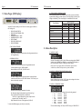
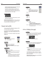
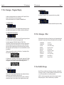
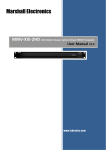
TCG
Time Code Generator
Software option for the SR-112
Owner’s manual
Version 3.00
January 2013
All materials herein © Brainstorm Electronics, Inc.
Brainstorm Electronics reserves the right to change or modify the
contents of this manual at any time.
Credits
Concept: AID, Brainstorm Electronics
Software: Gerry Lester
Manual: Bernard Frings, Gerry Lester
Technical Assistance: Jim Pace
Brainstorm Electronics, Inc.
www.brainstormtime.com
Page 2
TCG User Manual
Table of contents
1. INTRODUCTION . . . . . . . . . . . . . . . . . . . . . . . . . . . . . . . . . . . . . . . . . . . . . .
2. INSTALLATION . . . . . . . . . . . . . . . . . . . . . . . . . . . . . . . . . . . . . . . . . . . . . . .
3. QUICK START . . . . . . . . . . . . . . . . . . . . . . . . . . . . . . . . . . . . . . . . . . . . . . . .
4. MODES OF OPERATION . . . . . . . . . . . . . . . . . . . . . . . . . . . . . . . . . . . . . . . .
5. STATUS PAGES (LCD DISPLAY) . . . . . . . . . . . . . . . . . . . . . . . . . . . . . . . . . . .
6. MENUS DESCRIPTIONS . . . . . . . . . . . . . . . . . . . . . . . . . . . . . . . . . . . . . . . . .
01 - Mode . . . . . . . . . . . . . . . . . . . . . . . . . . . . . . . . . . . . . . . . . . . . . . .
09 - Alternate Phase with 50&60Hz Video . . . . . . . . . . . . . . . . . . . . . . .
10 - Generator Format . . . . . . . . . . . . . . . . . . . . . . . . . . . . . . . . . . . . . .
11 - Generator Video Ref . . . . . . . . . . . . . . . . . . . . . . . . . . . . . . . . . . . .
12 - Generator Delay . . . . . . . . . . . . . . . . . . . . . . . . . . . . . . . . . . . . . .
13 - Generator Start Time . . . . . . . . . . . . . . . . . . . . . . . . . . . . . . . . . . .
14 - Generator User Bits . . . . . . . . . . . . . . . . . . . . . . . . . . . . . . . . . . . .
20 - Repair Mode . . . . . . . . . . . . . . . . . . . . . . . . . . . . . . . . . . . . . . . . .
21 - Repair Flywheel Time . . . . . . . . . . . . . . . . . . . . . . . . . . . . . . . . . . .
22 - Repair Ramp Up Time . . . . . . . . . . . . . . . . . . . . . . . . . . . . . . . . . .
23 - Repair Input Persistency . . . . . . . . . . . . . . . . . . . . . . . . . . . . . . . . .
24 - Repair Time Code Jam Window . . . . . . . . . . . . . . . . . . . . . . . . . . .
98 - Feature Key . . . . . . . . . . . . . . . . . . . . . . . . . . . . . . . . . . . . . . . . . .
TCG User Manual
Page 3
3. Quick Start
2
2
3
3
4
5
5
5
5
6
6
6
6
6
6
7
7
7
8
7. GENERATOR SWITCHES AND LED’S . . . . . . . . . . . . . . . . . . . . . . . . . . . . . . . 8
8. ERRORS: LCD DISPLAY (STATUS PAGES) . . . . . . . . . . . . . . . . . . . . . . . . . . . . 9
9. ERROR MESSAGES: 7 SEGMENT DISPLAY . . . . . . . . . . . . . . . . . . . . . . . . . . 10
10. OTHER ERROR MESSAGES . . . . . . . . . . . . . . . . . . . . . . . . . . . . . . . . . . . . 11
11. NON-VOLATILE MEMORY . . . . . . . . . . . . . . . . . . . . . . . . . . . . . . . . . . . . . 11
12. GENLOCKING TO A 50/60HZ VIDEO REFERENCE . . . . . . . . . . . . . . . . . . 12
3.1. GENERATE NEW TIME CODE
-
Menu 01: select GENERATE
Menu 10: select the time code FORMAT
Menu 11: select VIDEO REFERENCE (if required)
Menu 13: set the START time
Press the [GEN RUN] key on the front panel
3.2. REGEN TIME CODE
-
Menu
Menu
Menu
Menu
Menu
01: select REPAIR
10: select the time code FORMAT
11: select VIDEO REFERENCE (if required)
20: select COPY
21: change the flywheel time (if required - 5fr default)
3.3. JAM SYNC TIME CODE
-
Menu
Menu
Menu
Menu
Menu
01: select REPAIR
10: select the time code FORMAT
11: select VIDEO REFERENCE (if required)
20: select JAM
21: change the flywheel time (if required - 5fr default)
4. Modes of Operation
With the TCG, menu 01 has 2 new modes of operation: GENERATE and REPAIR.
1. Introduction
The TCG option enables the SR-112 to generate time code, locked to an external
video reference or not, for multiple applications:
•
•
•
•
Generate new master time code, at any standard rate;
Regenerate existing time code (eliminating drop outs and reducing jitter);
Jam sync locked to external video;
Delay time code up to 60 msec (useful when aligning audio to video)
2. Installation
Be sure to update your SR-112 with the latest firmware (for information, please refer
to pages 16-19 of the SR-112 User’s Manual).
Once you have registered your TCG purchase, you will receive a unique
authorization key, a series of 4 numbers, separated by periods. This key is only valid
for the SR-112 with the serial number used during ordering.
Enter this code via Menu 98 (Feature Key - see page 8) then reboot your unit. This
authorization procedure only needs to happen once, even with subsequent firmware
updates.
4.1. GENERATE
In this mode, you can generate any format time code, locked to the SR-112
internal crystal or referenced to an external video (SD or HD).
Set a start time (menu 13) and press the [GEN RUN] button on the front panel.
4.2. REPAIR
Repair has 2 options: COPY and JAM:
• COPY indicates that the generator continuously copies the time code
input, as long as it continues to increment. It is the default value of the
REPAIR mode.
This is used for eliminating drop-outs and reducing jitter on existing code.
• JAM indicates that a one-time copy of the input time code is transferred to
the generator shortly after the input time code achieves play velocity. The
generator then increments as it would in GENERATE mode.
This is used for generating new code from a known start point.
GENERATE to VIDEO REF mode and REPAIR modes can be used in conjunction
with the DELAY feature as described in 6.5, menu 12.
Page 4
TCG User Manual
5. Status Pages (LCD Display)
TCG User Manual
Page 5
5.1. STATUS PAGES & OPERATING MODES
Some of the status pages are only available in certain modes, as shown in the following table. When switching to another mode, the current status display is preserved, but
changes to the default (*) if the current display is not available in the new mode.
Status Display
With the TCG option installed, your SR-112 has 3 new status pages, in addition to
the 5 existing ones:
•
•
•
•
•
•
•
•
TIME CODE INPUT STATUS
TIME CODE INPUT READER - NEW USER BITS IN
GENERATOR STATUS 1 - NEW GENERATOR STATUS 2 - NEW VIDEO FORMAT
TIME CODE/ VIDEO PHASE
TIME CODE ERRORS
• TIME CODE INPUT READER
Gives visibility to the timecode input at times when the generator takes over
the 7-segment display.
• GENERATOR STATUS 1
Indicates the format and the frame rate of the generated time code.
Formats available are 24, 25, 30DF and 30ND.
Rates available are 23.976, 24, 25, 29.970 and 30.
The “XFrm” indicator comes on when the generator is creating 24 frame
code locked at 23.976Hz to an NTSC video reference. This is the only cross
frame mode currently supported.
• GENERATOR STATUS 2
Operating Modes
Reshape
Repair
Generate
TIME CODE INPUT STATUS
Y*
Y*
-
TIME CODE INPUT READER
-
Y
-
USER BITS IN
Y
Y
-
GENERATOR STATUS 1
-
Y
Y*
GENERATOR STATUS 2
-
Y
Y
VIDEO FORMAT
Y
Y
Y
TIME CODE / VIDEO PHASE
Y
Y
-
TIME CODE ERRORS
Y
Y
Y
6. Menus Description
6.1. MENU 01: MODE
With the TCG enabled, the SR-112 has 3 different operating modes: RESHAPE
(default value), GENERATE and REPAIR. A corresponding LED illuminates on
the front panel (Status Section) to indicate the current selection.
Note: Menu 01 only appears when the TCG software option has been
installed since, without it, Reshape is the only mode available.
6.2. MENU 09: ALTERNATE PHASE WITH 50&60Hz VIDEO
Menu 09 allows the user to switch “A”/”B” phases when working with a 2x rate
video input. See chapter 12 for more information.
6.3. MENU 10: GENERATOR FORMAT
The bottom line of this page is separated in 3 sections:
Left: Indicates the Repair Mode selected in menu 20 (Jam/Copy)
Center: Indicates the Generator Delay in milliseconds.
The “DLY=xx” segment illuminates only when a delay has been
requested via the “Gen Delay” menu 12.
Right: Indicates the lock status of the regenerator (Unlk/Lock)
To access these different pages, press the [up] or [down] key.
Select from the following options the type of time code to be generated:
• 24
at a rate of
23.976
• 24
at a rate of
24.000
• 25
at a rate of
25.000
• 30DF
at a rate of
29.970
• 30ND
at a rate of
29.970
• 30DF
at a rate of
30.000
• 30ND
at a rate of
30.000
This menu indicates settings. For Status, exit SET UP and go to ‘GEN STATUS 1’.
Page 6
TCG User Manual
TCG User Manual
Page 7
6.4. MENUS 11: GENERATOR VIDEO REF
Menu 21 sets the interval of time during which this happens. The choices are:
5 fr, 15 fr or infinity. Default value is 5 fr.
This selection determines if the generator is video referenced or not.
NOTE: If VID REF is selected in menu 11 but no video is present at the rear
panel connector, the front panel VIDEO REF LED will blink continuously.
With INFINITY selected, press the [gen
run]
button to stop the generator.
6.10. MENUS 22: REPAIR RAMP UP TIME
6.5. MENUS 12: GENERATOR DELAY
Menu 12 lets you enter a value in milliseconds to delay the generator output in
‘REPAIR’ or ‘GEN w/ video ref’ modes. This value goes up to 60 milliseconds.
This function is useful to delay the audio when it is ahead of the video.
The “Gen Delay” menu is unique in that the generator delay is dynamically
adjusted as the menu value is incremented or decremented. It is not necessary
to press the [enter] key for the new value to take effect.
When the TCG starts running and a delay has
been requested, the 7-segment display indicates
“Gen dly” for about 2 seconds (see 9.1).
This requested delay appears in the GEN STATUS 2 page (see page 4).
6.6. MENUS 13: GENERATOR START TIME
During the “Ramp Up” period the generator is inactive, and input code is
switched to the outputs as it would be in RESHAPE mode. Only at the end of
the “Ramp Up” period does the generator start to actively seek an opportunity
to begin jamming input time code into the generator stream.
Default “Ramp Up” is “None” and can be adjusted from “None” to 9.5 sec
with 0.5 sec increments.
6.11. MENUS 23: REPAIR INPUT PERSISTENCY
The “Persistency” is the number of consective frames that the input time code
must be seen to be incrementing normally before the generator jams the input
time code into the generator stream.
The default value is 5 frames. It can be adjusted from None to 99 frames.
This sets the frame number at which the TCG starts when [gen
run]
is pressed.
If the generator is on “Copy” mode, then the generator jams the input time
code as long as the input time code continues to increment.
6.7. MENUS 14: GENERATOR USER BITS
There are two special “Persist” settings:
This sets the User Bits of the generated time code.
6.8. MENUS 20: REPAIR MODE
Two Repair options are available: COPY (default) and JAM.
• COPY: the TCG continuously reads the time code input and regenerates the
exact same numbers. It is the default value of Menu 20.
• JAM: a one-time copy of the input time code is transferred to the generator
shortly after the input time code achieves play velocity. The generator then
increments as it would in GENERATE mode.
6.9. MENUS 21: REPAIR FLYWHEEL TIME
If the source time code drops out or becomes unreadable, the TCG repairs this
by flywheeling over the ‘bad’ area, generating good code.
- “None” means that there is no requirement for the input time code to be incrementing at all, and that the generator will use any valid number that it receives.
- “None:No Comp” is the same as “None”, but the usual methods of incrementing
time code to compensate for internal reader and generator delays is discarded.
The input time code is transferred unaltered to the generator stream and in that
way, as long as input time code remains valid, every input frame will be accounted
for in the output stream.
The disadvantage of this mode is that there is a two (2) frame delay between
the input time code and the output generator code.
6.12. MENUS 24: REPAIR TIME CODE JAM WINDOW
The repair “Window” setting is used only while the generator is locked to a
video reference and while it is copying or jamming from input time code. It
specifies, as a percentage of a frame, the size of the “window” on either side
Page 8
TCG User Manual
of the video frame edge within which the input time code frame edge must fall
before the input code will be recognized by the generator.
The default 25% should be perfectly adequate to accomodate time code
which is not quite correctly in phase with the video reference. If however, for
example, the input time code is locked to the wrong video field, then it may be
necessary to open up this “window” to 50% or higher.
6.13. MENUS 98: FEATURE KEY
Menu 98 lets you enter a unique key to authorize certain features on your SR-112,
such as the TCG. See ‘Installation’ page 2.
IMPORTANT NOTE ON MENU OPERATION: Remember to always press the [enter]
key to save your settings prior to exiting a menu or to exiting the SET UP mode.
No change will take place until the [enter] key is pressed.
7. Generator Switch and LED’s
The front panel switch and LED’s have different functions depending on the SR-112
mode of operation (Reshape / Repair / Generate).
Here is a description of each under the 3 different modes. Brackets are added to
indicate that operation is identical in REPAIR and GENERATE (GEN RUN LED and
VIDEO REF LED).
Note that the “TC IN”, “OUT OF PHASE” and “DRIFTING” LEDs are disabled in
GENERATE mode.
7.1. GENERATOR RUN SWITCH
RESHP: Ignored
REPAIR: Stops Generator when in Flywheel mode
GEN: Starts / stops generator
7.2. VIDEO REF LED
RESHP:Off
REPAIR Off: Generator is not video referenced
/GEN: On: Generator is video referenced
Blink:Generator is in VIDEO REF mode but video is not present.
7.3. GENERATOR RUN LED
RESHP:Off
REPAIR Off: (generator not running)
/GEN: On: Generator is running, and generator code has been switched
to the outputs
Blink:Generator is running as above, but has entered the infinite
flywheel state.
- to stop the generator press the [genrun] key. (Note that if the
input code has started running again prior to pressing [genrun], then the generator will at that time re-sync and re-jam.)
TCG User Manual
Page 9
7.4. RESHAPE LED
RESHP: REPAIR: GEN: On
Normally off
But blinks when generator is bypassed and input
code is active (typically during jam/copy ramp up
or if input code is not within menu 23 or 24 specs)
Off
7.5. REPAIR LED
RESHP:Off
REPAIR:On
GEN: Off
7.6. GENERATE LED
RESHP:Off
REPAIR: Normally off
- but illuminated solidly when either:
(a) generator has entered flywheel mode (source stopped)
or (b) generator is in jam mode and past the jam point
GEN: Normally on but blinks if Video reference is selected and generator is
not currently locked to the video
8. Errors - LCD Display (status pages)
8.1. GEN STATUS 1
The timecode type and/or rate values in the GEN STATUS 1 page will blink
continuously to indicate a generator settings mismatch. For example, when
generating ‘30DF 30.000’ referenced to 29.97 NTSC video.
For more information on GEN STAT errors, see 9.2 below.
8.2. GEN STATUS 2
The “Copy” or “Jam” indicator in the GEN STATUS 2 page will blink in REPAIR
mode when the Generator is attempting to copy or jam input timecode.
While blinking, the Generator is waiting for:
• the input timecode edge to fall within the “Repair Window” specified in
Menu 24 and
• the input timecode to increment persistently as specified in Menu 23.
Continuous blinking indicates a problem in one of these areas. The problem
might be solvable by adjusting either Menu 23 or Menu 24, or it might be that
the situation is simply impossible.
Confirming that the generator is unable to perfom the repair, the RESHAPE LED
will blink continuously as well (see 7.4 above).
Page 10
TCG User Manual
9. Error Messages - 7-Segment Display
In addition to the timecode reader errors reported by the SR-112 (see SR-112 User
Manual 11.3), the TCG has some new error messages.
Note that timecode Reader errors are disabled in GENERATE mode.
9.1. GENERATOR DELAY
TCG User Manual
Page 11
9.4. GENERATOR SYNC
This message is displayed in case of a Generator Sync Error (very unlikely).
9.5. GENERATOR FAILURE
This message is displayed in case of a Generator Internal Failure (even more unlikely).
This message (informational, not an error) is displayed when generator starts running
and a delay has been requested in menu 12 (Repair, or Generate to Vid Ref only)
9.2. GENERATOR SETTINGS MISMATCH
This message indicates a condition where the current TCG timecode type and/or rate
is not the same as the “Gen Format” menu setting (menu 10).
For example, generating ‘30DF 30.000’ locked to 29.97 NTSC video.
The generator will use the timecode type and rate from the menu setting until such
time as the requisite video and/or timecode inputs are connected. At that time it
may have to adjust the generated type and rate if the menu values are incompatible with the video and/or timecode inputs. This is when the GEN-STAT error would
be established.
The timecode type and/or rate values in the “Gen Status 1” status display will also
blink continuously to indicate the mismatch.
It is important not to confuse Menu 10 and the Gen Status 1 page. Menu 10 indicates
a setting not a status. The Gen Status 1 page will indicate the actual format and rate
of the generator output and flash if it doesn’t match the settings of menu 10.
9.3. CODE - VIDEO
This error, active in Repair mode with video reference only, indicates that the input
timecode type cannot be matched up with the video rate.
This is re-assessed every time the input timecode enters play motion, or following a
timecode type change, or when a reference is first recognized at the video input.
10. Error Messages - Other
The following time code input errors will not be shown on the 7-segment display while
the Generator is running. They will however still be added to the error report listing.
“CODE ERR”
“CODESTOP”
“CF CHG “
“DF ERR “
“DISCONT “
“DF CHG “
“DROP OUT”
“TYPE CHG”
“INVALID “
“REPEAT “
-
-
-
-
-
-
-
-
-
-
Code Error
Code Stopped
Color Frame Change
Drop Frame Error
Discountinuity
Drop Frame Change
Code Drop Out
Code Type Change
Invalid Address
Repeated Frame
11. Non-Volatile Storage
The SR-112 has non-volatile memory holding the current settings, including all the
TCG settings. This memory is continuously updated so that, when the unit is turned
on, it is in the same condition as it was when powered down.
NOTE: You should wait approximately 10 seconds after a change was entered
before powering down, to allow for the flash memory to be updated.
Page 12
TCG User Manual
12. Genlocking to a 50/60 Hz Video Reference
SMPTE time code was developed for analog television operating with rates up to
30 f/s. With digital television, progressive video systems have frame rates up to
50 and 60 f/s. In these systems, counting is done on frame pairs and the video
reference point is the start of line 1 of the first frame of the frame pair to which the
LTC is associated.
When using 2x video rates (50, 59.94, 60Hz) for synchronizing the generator
frame, the TCG extracts a 1x rate (25, 29.94, 30Hz) from the video, and it does
this by arbitrarily discarding every second input video frame edge. Conceptually
the input video frame sequence can be thought of as a sequence of pairs of
frames, with the first frame of each pair denoted as “A” and the second as “B”.
(This is a purely imaginary construct of course, as the frames themselves are
indistinguishable one from the other.)
12.1. MENU 09
When the SR-112 first powers up, if a 2x video rate is selected as its reference,
then it will initially lock to the “A” frames and discard the “B” frames. This will
normally be a satisfactory arrangement, but it is possible that the SR-112 will be
using the “A” frames when the user would prefer that the “B” frame edges are
followed. This may come up, for example, when the output timecode turns out to
be 180 degrees out of phase with other pieces of equipment that have landed on
the alternate video phase.
Menu 09 lets you switch “A”/”B” phases. The “A” or “B” values have no
particular significance. The menu simply allows the phase to be reversed from its
current orientation.
Where adjustment is required, menu 09 may have to be re-adjusted every time the
SR-112 is powered up and/or every time that a new 2x video reference is either
selected or plugged into the SR-112 reference video input.