1
Solar Inverter
SUNNY BOY / SUNNY MINI CENTRAL
User Manual
SB_SMC-BEN092840 | TBE-ALL | Version 4.0
EN
SMA Solar Technology AG
Table of Contents
Table of Contents
1
1.1
1.2
1.3
1.4
Notes on this Manual. . . . . . . . . . . . . . . . . . . . . . . . . . . . . .
Area of Validity. . . . . . . . . . . . . . . . . . . . . . . . . . . . . . . . . . . . . .
Target Group . . . . . . . . . . . . . . . . . . . . . . . . . . . . . . . . . . . . . . .
Additional Information . . . . . . . . . . . . . . . . . . . . . . . . . . . . . . . .
Symbols Used . . . . . . . . . . . . . . . . . . . . . . . . . . . . . . . . . . . . . . .
5
5
5
5
5
2
2.1
2.2
2.3
Safety . . . . . . . . . . . . . . . . . . . . . . . . . . . . . . . . . . . . . . . . . . 7
Appropriate Usage . . . . . . . . . . . . . . . . . . . . . . . . . . . . . . . . . . . 7
Safety Precautions. . . . . . . . . . . . . . . . . . . . . . . . . . . . . . . . . . . . 9
Identifying the product . . . . . . . . . . . . . . . . . . . . . . . . . . . . . . . 10
3
3.1
3.2
Operating Modes. . . . . . . . . . . . . . . . . . . . . . . . . . . . . . . . 11
Activating the Display Illumination . . . . . . . . . . . . . . . . . . . . . . 12
Initial Phase. . . . . . . . . . . . . . . . . . . . . . . . . . . . . . . . . . . . . . . . 12
3.2.1
All LEDs are on . . . . . . . . . . . . . . . . . . . . . . . . . . . . . . . . . . . . . . . . . . . . . . . 12
3.3
Normal Operation . . . . . . . . . . . . . . . . . . . . . . . . . . . . . . . . . . 12
3.3.1
All LEDs are off . . . . . . . . . . . . . . . . . . . . . . . . . . . . . . . . . . . . . . . . . . . . . . . 12
3.3.2
The green LED is continuously on . . . . . . . . . . . . . . . . . . . . . . . . . . . . . . . . . 13
3.3.3
The green LED is blinking slowly . . . . . . . . . . . . . . . . . . . . . . . . . . . . . . . . . 13
3.3.4
The green LED is blinking rapidly . . . . . . . . . . . . . . . . . . . . . . . . . . . . . . . . . 13
3.3.5
The green LED goes out briefly . . . . . . . . . . . . . . . . . . . . . . . . . . . . . . . . . . . 14
3.4
Failures . . . . . . . . . . . . . . . . . . . . . . . . . . . . . . . . . . . . . . . . . . . 15
3.4.1
The red LED is continuously on . . . . . . . . . . . . . . . . . . . . . . . . . . . . . . . . . . . 16
3.4.2
The Red LED is blinking . . . . . . . . . . . . . . . . . . . . . . . . . . . . . . . . . . . . . . . . . 17
3.4.3
The yellow LED is continuously on. . . . . . . . . . . . . . . . . . . . . . . . . . . . . . . . . 17
3.4.4
The yellow LED blinks twice. . . . . . . . . . . . . . . . . . . . . . . . . . . . . . . . . . . . . . 18
3.4.5
The yellow LED blinks three times . . . . . . . . . . . . . . . . . . . . . . . . . . . . . . . . . 19
3.4.6
The yellow LED blinks 4 times . . . . . . . . . . . . . . . . . . . . . . . . . . . . . . . . . . . . 20
3.4.7
The yellow LED blinks 5 times . . . . . . . . . . . . . . . . . . . . . . . . . . . . . . . . . . . . 21
3.4.8
The yellow LED blinks 6 times . . . . . . . . . . . . . . . . . . . . . . . . . . . . . . . . . . . . 22
User Manual
SB_SMC-BEN092840
3
Table of Contents
SMA Solar Technology AG
3.4.9
The yellow LED blinks 7 times . . . . . . . . . . . . . . . . . . . . . . . . . . . . . . . . . . . . 23
4
4.1
4.2
Information on the Display . . . . . . . . . . . . . . . . . . . . . . . . 24
Display Messages in the Startup Phase . . . . . . . . . . . . . . . . . . 24
Display Messages During Operation . . . . . . . . . . . . . . . . . . . . 25
4.2.1
Display Messages when Fault Warnings Occur . . . . . . . . . . . . . . . . . . . . . . 25
4.2.2
Display Messages for Plant Disturbances . . . . . . . . . . . . . . . . . . . . . . . . . . . 26
4.2.3
Rapid Blinking of Background Illumination . . . . . . . . . . . . . . . . . . . . . . . . . . 26
5
5.1
Maintenance and Cleaning . . . . . . . . . . . . . . . . . . . . . . . . 27
Checking Heat Dissipation . . . . . . . . . . . . . . . . . . . . . . . . . . . . 27
5.1.1
Cleaning the Cooling Fins . . . . . . . . . . . . . . . . . . . . . . . . . . . . . . . . . . . . . . . 27
5.1.2
Cleaning the Fans . . . . . . . . . . . . . . . . . . . . . . . . . . . . . . . . . . . . . . . . . . . . . 27
5.2
Cleaning the Display. . . . . . . . . . . . . . . . . . . . . . . . . . . . . . . . . 27
6
6.1
6.2
6.3
Measurement Channels and Messages . . . . . . . . . . . . . . 28
Measuring Channels. . . . . . . . . . . . . . . . . . . . . . . . . . . . . . . . . 28
Status Messages . . . . . . . . . . . . . . . . . . . . . . . . . . . . . . . . . . . . 29
Error messages . . . . . . . . . . . . . . . . . . . . . . . . . . . . . . . . . . . . . 31
7
Glossary . . . . . . . . . . . . . . . . . . . . . . . . . . . . . . . . . . . . . . . 42
8
Contact . . . . . . . . . . . . . . . . . . . . . . . . . . . . . . . . . . . . . . . . 45
4
SB_SMC-BEN092840
User Manual
SMA Solar Technology AG
Notes on this Manual
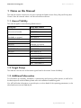
1 Notes on this Manual
This manual contains instructions on how to operate the SMA inverters Sunny Boy and Sunny Mini
Central. Store this manual where it will be accessible at all times.
1.1 Area of Validity
This manual applies to the following SMA inverters:
Sunny Boy
SB 1100
(discontinued model)
SB 1200
(available on request)
SB 1700SB 1700
SB 2100TL
SB 2500
SB 3000
SB 3300TL HC
SB 3300
SB 3800
Sunny Mini Central
SMC 4600A
SMC 5000A
SMC 6000A
SMC 6000TL
SMC 7000HV
SMC 7000HV-11
(available on request)
SMC 7000TL
SMC 8000TL
SMC 9000TL-10
SMC 9000TLRP-10
SMC 10000TL-10
SMC 10000TLRP-10
SMC 11000TL -10
SMC 11000TLRP-10
1.2 Target Group
This manual is for the user of the inverter types listed in the section "Area of Validity".
1.3 Additional Information
For information on assembly, installation, commissioning and servicing of the inverter, as well as for
the device-specific technical data, please refer to the attached installation guide.
You will find further information on special topics, such as details of the operating parameters, in the
download area at www.SMA.de/en.
User Manual
SB_SMC-BEN092840
5
Notes on this Manual
SMA Solar Technology AG
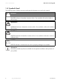
1.4 Symbols Used
The following types of safety instructions and general information are used in this manual:
DANGER!
DANGER indicates a hazardous situation which, if not avoided, will result in death or
serious injury.
WARNING!
WARNING indicates a hazardous situation which, if not avoided, could result in death or
serious injury.
CAUTION!
CAUTION indicates a hazardous situation which, if not avoided, could result in minor or
moderate injury.
NOTICE!
NOTICE indicates a situation that can result in property damage if not avoided.
Information
Information provides tips that are valuable for the optimum installation and operation of
your product.
6
SB_SMC-BEN092840
User Manual
SMA Solar Technology AG
Safety
2 Safety
2.1 Appropriate Usage
The Sunny Boy / Sunny Mini Central is a solar inverter which converts the DC current of the PV
generator to AC current and feed it into the public grid.
More precise information on this subject and on your device can be found in the installation guide.
The operational limits specified in the installation guide for the particular inverter must be observed.
All inverters may only be operated with PV generators (modules and cabling) of Protection Class II
rating. Do not connect any sources of energy other than PV modules to the inverter.
Do not use the inverter for purposes other than those described here. Alternative uses, modifications
to the inverter or the installation of components not expressly recommended or sold by the
manufacturer void the warranty claims and operating permission. If you have questions regarding the
proper usage of the inverters, please contact the SMA Solar Technology Serviceline.
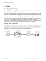
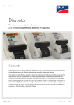
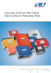
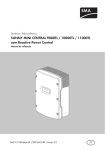
Principle of the string inverter
The string inverter is used to connect a small number of series-connected solar modules (strings) to the
public supply grid. This way, even a large PV generator can be constructed from a large number of
individual strings, each having its own string inverter. The energy is then combined on the AC side.
Principle of a grid-connected PV system with a Sunny Boy
Sunny Boy
PV-Modules
User Manual
Distribution
Public grid
SB_SMC-BEN092840
7
Safety
SMA Solar Technology AG
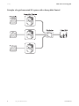
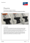
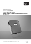
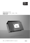
Principle of a grid-connected PV system with a Sunny Mini Central
8
SB_SMC-BEN092840
User Manual
SMA Solar Technology AG
Safety
2.2 Safety Precautions
DANGER!
High voltages in the inverter. Death resulting from electric shock and burns.
The following work on the inverter must be carried out by a qualified personnel only.
• Electrical installation
• Repairs
• Modifications
Even when no external voltage is applied, high voltages can still be present in the device.
These high voltages can result in death or serious injury.
CAUTION!
Enclosure body can get hot during operation. Risk of burn injuries. Do not touch.
The temperature of some parts of the inverter enclosure – in particular the temperature of
the heatsinks – can reach over 60 °C in normal operation.
• Only touch lid and display during operation.
NOTICE!
Overvoltages in the inverter Destruction of the inverter and voiding of warranty
claims.
• Please contact your installer whenever the inverter reports an error.
User Manual
SB_SMC-BEN092840
9
Safety
SMA Solar Technology AG
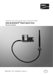
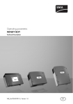
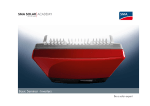
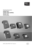
2.3 Identifying the product
You can identify the inverter by the type plate. The type
plate is usually located on the right side of the enclosure.
The type plate specifies among other things the device
type (Type / Model), the serial number (Serial No.) and
the device-specific key data of the product.
The type plate illustrated here is a typical example
showing the Sunny Boy 3800.
10
SB_SMC-BEN092840
User Manual
SMA Solar Technology AG
Operating Modes
3 Operating Modes
The different operating modes are indicated by 3 light-emitting diodes (LEDs) on the inverter lid, and
also via the integrated display (see Section 4 "Information on the Display" (page 24)). To allow the
device to signal its operating mode via the 3 integrated LEDs, the inverter must be connected to the
DC side of the system. The level of solar irradiation must be high enough to supply the inverter with
sufficient DC voltage.
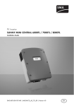
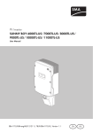
The following diagram shows the 3 LEDs, as exemplified by the Sunny Boy 3800.
LED
Green
Red
Meaning
In operation
Ground fault or varistor
defective
Inverter
All Sunny Boys / Sunny Mini Centrals
For the Sunny Boy models SB 1100, SB 1200,
SB 1700, SB 2100TL, SB 2500, SB 3000, SB 3300,
SB 3300TLHC, SB 3800
and Sunny Mini Central models SMC 4600A,
SMC 5000A, SMC 6000A, SMC 7000HV,
SMC 6000TL, SMC 7000TL, SMC 8000TL.
Ground fault, varistor defective For Sunny Mini Central models SMC 9000TL-10,
or string fuse defective
10000TL-10, 11000TL-10 and SMC 9000TLRP-10,
10000TLRP-10, 11000TLRP-10
Yellow Disturbance
All Sunny Boys / Sunny Mini Centrals
LED Display
If you do not have any means of plant communication, it is advisable, particularly during
the first year of operation, to keep a close eye on this display at different times of day and
under varying solar irradiation conditions. This will enable you to recognize errors at an
early stage.
A detailed description of the possible LED signals and blink codes is given in the following section.
User Manual
SB_SMC-BEN092840
11
Operating Modes
SMA Solar Technology AG
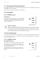
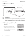
3.1 Activating the Display Illumination
The background illumination is switched on by tapping on the enclosure lid. Tapping again switches
the display on to the next message.
After 2 minutes, the illumination switches off automatically.
3.2 Initial Phase
3.2.1 All LEDs are on
Initialization
The inverter's on-board computer is now in the initializing
phase. The on-board power supply is present, but there is
insufficient energy for feeding the grid. Data transmission
is also not possible yet.
All LEDs are blinking
If during the initialization phase the energy fed into the inverter is not sufficient to power
the on-board computer, all LEDs are extinguished. After this, initialization restarts. If there
is very weak solar irradiation, the LEDs appear to blink. This apparent blinking indicates a
normal operating mode. No fault has occurred in the system.
3.3 Normal Operation
If no LED, or only the green LED is on or blinking, the inverter is operating normally. If all 3 LEDs are
lit up simultaneously, this is also an indication of normal operation ("initialization"). All other signals
are a sign of faulty operation.
3.3.1 All LEDs are off
Overnight Shutdown
The inverter is in the so-called overnight shutdown mode.
This situation occurs if the inverter's input voltage is too
low both for feeding into the grid and for satisfying the onboard voltage requirements.
If this operating mode occurs during a sunny day with
good irradiation, have the PV voltage checked by your
installer.
12
SB_SMC-BEN092840
User Manual
SMA Solar Technology AG
Operating Modes
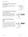
3.3.2 The green LED is continuously on
Feeding Operation
The inverter has passed the self-tests of the measurement
electronics and grid monitoring, and is now in normal
grid-feed operation.
3.3.3 The green LED is blinking slowly
Waiting, Grid Monitoring
The inverter is checking if the start conditions necessary
for feeding the grid (e.g. start voltage, start time) are
fulfilled, and then begins monitoring the grid. The PV
voltage must reach the specified minimum value at least
once before the inverter begins feeding into the grid.
3.3.4 The green LED is blinking
rapidly
Stop
The inverter is in "Stop" mode. This occurs, for instance,
when the measurement electronics are being calibrated.
After this, the device switches to "Waiting" mode.
The "Stop" mode can be manually pre-set by the installer
via an appropriate communications product. In this case
the inverter remains in "Stop" mode until a new operating
mode ("MPP mode", "Constant voltage mode", "Turbine
mode") has been set.
User Manual
SB_SMC-BEN092840
13
Operating Modes
SMA Solar Technology AG
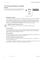
3.3.5 The green LED goes out briefly
Derating
The "Derating" mode is a normal operating mode which
may occur occasionally and can have several causes:
• Temperature derating
The temperature monitoring of the inverter has reduced the output power to prevent the device
from overheating. The inverter switches to the "Temperature derating" mode. If the Sunny Boy /
Sunny Mini Central frequently switches to this mode, please check the heat dissipation (see
Section 5.1 "Checking Heat Dissipation" (page 27)). For all Sunny Mini Centrals, as well as
the Sunny Boy models SB 3300 / SB 3800, check whether the fans are soiled.
Maintenance and Cleaning of the Fans
The fan cleaning procedure is described in the respective installation guide.
• Current derating
Due to the type of module or the output and wiring of the generator, the PV-side input current
exceeds the maximum possible input current. The inverter switches to the "Current derating"
mode in order to protect itself against overload.
• Output derating
This operating mode only occurs in systems which are operated using the Sunny Mini Central
with integrated SMA Power Balancer set to "PowerGuard".
• Frequency-dependent output derating P(f)
This operating mode occurs when the function which limits active power, P, is activated as a
function of grid frequency fAC.
You will find more detailed information on this function in the installation guide for Sunny Mini
Central 9000TL / 10000TL / 11000TL with Reactive Power Control.
14
SB_SMC-BEN092840
User Manual
SMA Solar Technology AG
Operating Modes
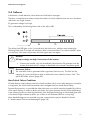
3.4 Failures
A distinction is made between critical and non-critical failure messages.
Thanks to a comprehensive safety concept the number of critical conditions that can occur has been
reduced to one single situation:
PV generator voltage is too high.
This is indicated by the following blink code on the yellow LED:
The yellow fault LED lights up for 5 seconds when the fault occurs, and then starts emitting the
following blink code: 3 seconds off and then 4 brief consecutive blinks. This code is emitted 3 times
in succession. If this fault is still present, the fault signal starts over again.
NOTICE!
DC input voltage too high. Destruction of the inverter.
• Contact your installer, who will immediately disconnect the PV generator from the
inverter and check the DC voltage, as described in the inverter's installation guide.
Generator Failure
The same blink code is generated when a generator failure occurs. This falls into the
category of a non-critical failure which is dealt with in more detail in Section 3.4.6 "The
yellow LED blinks 4 times" (page 20).
Non-Critical Failure Conditions
All other display codes indicate some form of fault condition which is not usually dangerous to people
or equipment, but which should nevertheless be investigated and corrected without delay.
Despite all precautions, it is possible that other faults may occur which cannot be signaled (e.g. failure
of the status display). In order to detect such faults, the system operator should use the explanations
in the following section to check the plausibility of the displayed mode (e.g. an illuminated green LED
in the dead of night indicates a defect, just as does a non-illuminated LED on a sunny day).
More detailed diagnoses are possible using the communications options detailed in Section
6 "Measurement Channels and Messages" (page 28).
User Manual
SB_SMC-BEN092840
15
Operating Modes
SMA Solar Technology AG
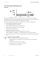
3.4.1 The red LED is continuously on
Insulation Fault or Defective Varistor
The red LED on the Sunny Boy / Sunny Mini Central is
permanently on. With this blink code it is irrelevant
whether the green or yellow LEDs are on or blinking. A
grounding error has occurred, or one of the thermally
monitored varistors on the DC input side is defective as a
result of overvoltage or ageing.
Sunny Mini Central 9000TL / 10000TL / 11000TL
Sunny Mini Central 9000TL / 10000TL / 11000TL with Reactive Power Control.
When the red LED lights up continuously, the inverter has detected a ground fault. A
separate blink code indicates a defective varistor or string fuse (see Section 3.4.2 "The
Red LED is blinking" (page 17)).
Inverter equipped with integrated grounding set
If the inverter is equipped with a "grounding set", a continuously lit red LED signals an
unwanted ground fault in the PV generator or a defect in the grounding set itself.
Further information on this subject can be found in the installation guide of the grounding
set.
Correction of error by installer
Contact your installer to have the error corrected. Instructions on correction errors can be
found in the inverter installation guide.
16
SB_SMC-BEN092840
User Manual
SMA Solar Technology AG
Operating Modes
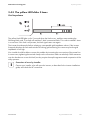
3.4.2 The Red LED is blinking
Fault on the DC side
Red LED blinking. This blink code overrides any signals on
the green or yellow LEDs.
This blink code can only occur in the following device types:
• SMC 9000TL-10 / 10000TL-10 / 11000TL-10
• SMC 9000TLRP-10 / 10000TLRP-10 / 11000TLRP-10
Possible causes:
– At least one of the varistors is defective. Display message <Check Varistor>
– At least one of the string fuses is defective. Display message: <DC fuse>
In both cases the inverter continues feeding into the grid.
Correction of error by installer
Contact your installer to have the error corrected. Instructions on correction errors can be
found in the inverter installation guide.
3.4.3 The yellow LED is continuously on
Permanent Disable
In the event of a recurring fault the inverter switches from
operating mode to "Permanent Disable" mode and
ceases grid feed.
A fault may have occurred that cannot be resolved onsite. If the inverter is equipped with a communications
interface, the installer can try to rectify the problem with
the help of a communications product. Should this be
unsuccessful, please contact the SMA Solar Technology
Serviceline (see Section8 "Contact" (page 45)) to
discuss further action to solve the problem.
User Manual
SB_SMC-BEN092840
17
Operating Modes
SMA Solar Technology AG
3.4.4 The yellow LED blinks twice
Grid fault
The yellow fault LED lights up for 5 seconds when the fault occurs, and then starts emitting the
following blink code. 3 seconds off and then 2 brief consecutive blinks. This code is emitted 3 times
in succession. If this fault is still present, the fault signal starts over again.
With this fault signal the inverter indicates a grid fault which can have the following causes:
• Grid undervoltage (voltage drop protection)
• Grid overvoltage (voltage rise protection)
• Grid underfrequency (frequency decrease protection)
• Grid overfrequency (frequency increase protection)
• Grid frequency change ("dFac")
• Voltage increase protection activated
• Faulty grid connections, e.g. N and L swapped or PE not connected
(SMC 9000TL(RP) / 10000TL(RP) / 11000TL(RP): Display message <Check L-N-PE>)
• In systems which consist of 3 or more Sunny Mini Centrals, the Power Balancer has detected a
fault.
Correction of error by installer
Contact your installer to have the following points checked:
• Check whether there is a general power failure (check function of other energy
consumers).
• Check the fuse of the inverter power supply.
• Check whether the circuit breaker is switched on.
• Check the inverter's grid connection.
18
SB_SMC-BEN092840
User Manual
SMA Solar Technology AG
Operating Modes
3.4.5 The yellow LED blinks 3 times
Grid impedance
The yellow fault LED lights up for 5 seconds when the fault occurs, and then starts emitting the
following blink code. 3 seconds off and then 3 brief consecutive blinks. This code is emitted 3 times
in succession. If this fault is still present, the fault signal starts over again.
The inverter has detected a failure relating to unacceptable grid impedance values. If the inverter
frequently displays this fault and switches off during grid monitoring, the cause may be that grid
impedance is too high.
Your installer should be able to correct this problem by increasing the cross-section of the power line.
In some cases, tightening the terminal clamps on the connection cable can also help. Other measures
can also be taken to correct this fault, but they require the explicit agreement and cooperation of the
utility operator.
Correction of error by installer
Contact your installer, who will open the inverter, as described in the inverter installation
guide, and check the AC connection.
User Manual
SB_SMC-BEN092840
19
Operating Modes
SMA Solar Technology AG
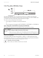
3.4.6 The yellow LED blinks 4 times
The yellow fault LED lights up for 5 seconds when the fault occurs, and then starts emitting the
following blink code. 3 seconds off and then 4 brief consecutive blinks. This code is emitted 3 times
in succession. If this fault is still present, the fault signal starts over again.
This code can be caused by either of the following:
• Input voltage has exceeded the maximal permissible limit.
or
• Error in the generator (only applies to SMC 9000TL(RP)-10, 10000TL(RP)-10, 11000TL(RP)-10).
Input voltage has exceeded the maximal permissible limit.
The voltage of the PV generator has exceeded the inverter's permissible input voltage.
NOTICE!
DC input voltage too high. Destruction of the inverter.
• Please contact your installer, who will immediately disconnect the PV generator from
the inverter and check the DC voltage, as described in the inverter installation guide.
Error in the Generator
In the inverter models Sunny Mini Central 9000TL / 10000TL / 11000TL (with Reactive Power
Control) this blink code can occur in combination with the display warning <Disturbance Earthfault>.
This signifies that the insulation resistance in the generator is too low.
Correction of error by installer
Please contact your installer to have the error corrected.
20
SB_SMC-BEN092840
User Manual
SMA Solar Technology AG
Operating Modes
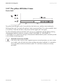
3.4.7 The yellow LED blinks 5 times
Device fault
The yellow fault LED lights up for 5 seconds when the fault occurs, and then starts emitting the
following blink code. 3 seconds off and then 5 brief consecutive blinks. This code is emitted 3 times
in succession. If after this the fault is still present, the fault signal starts over again.
For all transformerless devices this blink code can occur in combination with the display warning
<Disturbance Earthfault> (with the exception of SMC 9000TL(RP)-10, 10000TL(RP)-10,
11000TL(RP)-10, for which the warning is <Disturbance Earthfault-Sense>) and is caused by a fault
in the insulation monitoring system.
Correction of error by installer
If the device failure has a severe negative impact on normal operation, you must contact
your installer, who will check the inverter and the entire plant installation. It is essential to
ensure that devices without transformers (with "TL" in the device name) are correctly
grounded!
User Manual
SB_SMC-BEN092840
21
Operating Modes
SMA Solar Technology AG
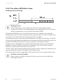
3.4.8 The yellow LED blinks 6 times
Discharge current too high
Discharge current
The fault "Discharge current too high" can only occur in transformerless inverters.
Transformerless inverters can be identified by their device designation. The "TL" in the name
stands for transformerless, e.g. Sunny Mini Central SMC 6000TL.
The yellow fault LED lights up for 5 seconds when the fault occurs, and then starts emitting the
following blink code. 3 seconds off and then 6 brief consecutive blinks. This code is emitted 3 times
in succession. If this fault is still present, the fault signal starts over again.
The discharge current from the inverter and the PV generator is too high. The Sunny Boy / Sunny Mini
Central interrupts grid feeding immediately after exceeding a threshold value and switches back onto
the grid automatically after testing. If necessary, testing will be repeated several times.
Discharge current is dependent on the capacity of the PV generator relative to ground and also
depends on the type of modules and manner of installation as well as the weather conditions.
Therefore, it is quite normal for this value to vary over time.
However, if the inverter frequently displays this fault, please notify the installer who installed your PV
system and clarify the reasons for the high level of discharge current.
This fault message can also be triggered by a PE connection which is not connected to the inverter.
Correction of error by installer
Please contact your installer to deal with the fault or get in touch with the SMA Solar
Technology Serviceline.
22
SB_SMC-BEN092840
User Manual
SMA Solar Technology AG
Operating Modes
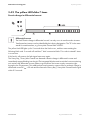
3.4.9 The yellow LED blinks 7 times
Drastic change in differential current
Differential current
The fault "Drastic change in differential current" can only occur in transformerless inverters.
Transformerless inverters can be identified by their device designation. The "TL" in the name
stands for transformerless, e.g. Sunny Mini Central SMC 6000TL.
The yellow fault LED lights up for 5 seconds when the fault occurs, and then starts emitting the
following blink code. 3 seconds off and then 7 brief consecutive blinks. This code is emitted 3 times
in succession.
If this fault is still present, the fault signal starts over again.
The Sunny Boy / Sunny Mini Central has detected a drastic change in differential current and
immediately stopped feeding into the grid. The integrated all-pole-sensitive residual current monitoring
unit monitors the differential current relative to ground from the inverter supply connection right
through to the PV generator. This additional personal protection system reacts to a drastic change in
differential current of IDN > 30 mA and disconnects the Sunny Boy / Sunny Mini Central from the grid
within 0.2 seconds.
User Manual
SB_SMC-BEN092840
23
Information on the Display
SMA Solar Technology AG
4 Information on the Display
Sunny Boy and Sunny Mini Central inverters are supplied with a factory-installed LC display on the
enclosure lid.
Display Messages
Detailed explanations of the individual error and fault messages can be found in Section
6 "Measurement Channels and Messages" (page 28).
A description and explanation of the operating parameters can be found in the Technical
Information "Operating parameters Sunny Boy / Sunny Mini Central“ in the download
area at www.SMA.de/en.
4.1 Display Messages in the Startup Phase
• After startup of the inverter, the display first shows
the device type.
• After 6 seconds, the firmware versions of the
operation control unit (BFR) and the current control
unit (SRR) are displayed.
• Inverters that are equipped with the SMA Power
Balancer subsequently indicate the operating mode
of the SMA Power Balancer.
24
SB_SMC-BEN092840
User Manual
SMA Solar Technology AG
Information on the Display
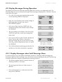
4.2 Display Messages During Operation
The display shows the most important operating data of the inverter in an alternating cycle. The
following diagrams serve to clarify the messages. Each message is displayed for 5 seconds. Then the
cycle starts over again.
• First of all, the energy generated that day and the
current operating mode are displayed.
• Next, the current feed-in power and the voltage of
the PV generator (except in the case of
SB 3300TLHC) appear.
• In the case of the Sunny Boy 3300TL HC, the
momentary feed-in power and the output voltage
are displayed.
Pac
Vac
903W
230V
• The next reading on the display of the Sunny Boy
3300TL HC gives the current input voltage and
input power.
Vpv
Ppv
520V
1325W
• In the case of the Sunny Mini Central with Reactive
Power Control, after a further 5 seconds or
following another tap, the current reactive power
value QAC and the displacement factor cos ϕ (PF)
are displayed.
QAC positive = overexcited
QAC negative = underexcited
• This is followed by the total energy produced so far
and the hours the device has been in operation.
4.2.1 Display Messages when Fault Warnings Occur
If a fault warning occurs, the display immediately switches to "Warning" and the background
illumination lights up. When warnings occur, the inverter continues feeding into the grid. The following
illustrations give three examples of possible fault warning scenarios.
• This warning appears after the inverter has been in
"Derating" mode for 10 minutes.
• This warning means that one of the varistors is
defective.
• If this warning appears, it means that one of the
string fuses is defective.
User Manual
Warning
Derating
Warning
Check Varistor
Warning
DC fuse
SB_SMC-BEN092840
25
Information on the Display
SMA Solar Technology AG
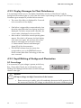
4.2.2 Display Messages for Plant Disturbances
If an operational failure occurs, the display immediately switches to "Disturbance" and the
background illumination lights up. In this case the inverter stops feeding into the grid. The following
illustrations give examples of possible failure scenarios.
• The cause of the failure is displayed for 5 seconds
in the second line of the display.
• If the failure is triggered by a measured value, then
the value measured at the time of going into fault is
displayed. If a further measurement is possible, the
current value is displayed in the second line.
• After another 5 seconds the normal operating data
appear. If the fault is still present, the fault display
cycle starts over again. An overview of the status
and error messages can be found in Section
6 "Measurement Channels and Messages"
(page 28) of this documentation.
• "Error ROM" indicates that the inverter has
recognized an error in the EEPROM firmware.
Please contact SMA Solar Technology to have the
error corrected.
4.2.3 Rapid Blinking of Background Illumination
DC Overvoltage
If an excessive DC input voltage is present at the Sunny
Boy / Sunny Mini Central, this is indicated by rapid
blinking of the background illumination and the message
shown on the right.
NOTICE!
DC input voltage too high. Destruction of the inverter.
• Please contact your installer, who will immediately disconnect the PV generator from
the inverter and check the DC voltage, as described in the inverter installation guide.
26
SB_SMC-BEN092840
User Manual
SMA Solar Technology AG
Maintenance and Cleaning
5 Maintenance and Cleaning
Check the correct operation of the inverter at regular intervals. Impurities such as dust or pollen can
cause heat accumulation that can lead to yield losses. Also check the inverters and the cables for
visible external damage. Have repairs carried out if necessary.
5.1 Checking Heat Dissipation
5.1.1 Cleaning the Cooling Fins
Applies to Sunny Boy models SB 1100, SB 1200, SB 1700, SB 2100TL, SB 2500, SB 3000
and SB 3300TLHC
CAUTION!
Danger of burn injuries due to hot enclosure parts!
• Do not touch the inverter's enclosure during operation.
The heat dissipation of the Sunny Boy can be restricted if the cooling fins are dirty.
• Clean the cooling fins with a suitable, soft brush.
5.1.2 Cleaning the Fans
Applies to Sunny Boy models SB 3300, SB 3800 and Sunny Mini Central
If the fan guards are only covered in loose dust, they can be cleaned with a vacuum cleaner. If
vacuum cleaning does not produce a satisfactory result, please contact your installer, who will
dismantle the fans for cleaning.
• The fan cleaning procedure is described in the respective installation guide and may only be
carried out by a qualified personnel.
5.2 Cleaning the Display
If the display or the status LEDs are so soiled that they can no longer be read, they should be cleaned
with a damp cloth.
• Never use solvents, abrasives or corrosive materials for cleaning!
User Manual
SB_SMC-BEN092840
27
Measurement Channels and Messages
SMA Solar Technology AG
6 Measurement Channels and Messages
If your inverter is equipped with a communication component, then numerous measurement channels
and messages to aid diagnosis can be transmitted.
The following abbreviations apply:
BFR: Operation control unit
SRR: Current control unit
6.1 Measuring Channels
Measuring
channel
Balancer
Earthfault / Riso
E-total
Error
Error-Cnt
Event-Cnt
Fac
Fault current
h-On
h-total
Iac
Ipv
Is
Mode
Power On
Pac
Phase
PF
Qac
Sac
Serial Number
Vac
Vfan,
Description
Displays the currently active operating mode of the Sunny Mini Central, which
has been set via the operating parameter "PowerBalancer".
Insulation resistance of the PV system before grid connection
Total amount of energy fed into the grid
Identification of the current disturbance / error.
Number of errors which have occurred since the last reset
Number of events which have occurred
Grid frequency
Differential current of the PV system (inverter and PV generator)
Total number of operating hours
Total number of grid-feeding operational hours
Grid current (active current)
DC current
Apparent current (applies only to inverters with Reactive Power Control)
Display of the current operating mode
Total number of grid connections
Generated AC power
The phase to which the inverter is connected. The phase (L1 - L3) is set via the
operating parameter "Grid connection".
Displacement factor cos ϕ (applies only to inverters with Reactive Power
Control)
Reactive power (applies only to inverters with Reactive Power Control)
Apparent power (applies only to inverters with Reactive Power Control)
Serial number of inverter
Grid voltage
Fan supply voltage (only in inverters equipped with an active cooling system)
V-Fan
28
SB_SMC-BEN092840
User Manual
SMA Solar Technology AG
Measuring
channel
Vpv
Vpv-Setpoint
Zac
Measurement Channels and Messages
Description
PV input voltage
PV target voltage
Grid impedance
6.2 Status Messages
The inverters can be in various operating modes. These are displayed as status messages which can
vary according to the method of communication.
Message
Balanced
Description and corrective measure
The Sunny Mini Central has disconnected from the grid, or is limiting its output to
5 kVA over a 10-minute average. The Sunny Mini Central is part of a three-phase
system equipped with two further Sunny Mini Centrals and the SMA Power
Balancer to avoid unbalanced load. The "Balanced" message is displayed for the
following reasons:
Case 1:
The operating parameter "PowerBalancer" is set to "PhaseGuard". One of the three
Sunny Mini Central inverters in this system has indicated a grid fault and
disconnected from the grid. Consequently, the other two Sunny Mini Central
inverters also disconnect from the grid to avoid an unbalanced load, and send the
message "Balanced".
Case 2:
The operating parameter "PowerBalancer" is set to "PowerGuard". One of the
3 Sunny Mini Centrals in this system has detected a device or grid fault and
disconnected from the grid. The two remaining Sunny Mini Centrals reduce their
output over a 10-minute average to 5 kVA in order to prevent an unbalanced load.
Case 3:
The operating parameter "PowerBalancer" is set to "FaultGuard". One of the 3
Sunny Mini Centrals in this system has indicated a device or grid fault and
disconnected from the grid.
When grid failure occurs, the other two Sunny Mini Centrals also disconnect from
the grid to prevent an unbalanced load, and send the message "Balanced".
In the event of a device fault, the fault message is sent to the other two devices with
a time lapse of 5 minutes. After the 5 minutes have passed, the other two devices
disconnect from the grid and send the message "Balanced".
User Manual
SB_SMC-BEN092840
29
Measurement Channels and Messages
Message
Derating
SMA Solar Technology AG
Description and corrective measure
Overtemperature in the inverter.
The inverter reduces its output to prevent the device from overheating.
Corrective measures
• In the case of fan devices check heat dissipation, as described in Section
5.1 "Checking Heat Dissipation" (page 27).
• To avoid unnecessary yield losses, your installer should check the
configuration and string size.
• The installer should also check whether the inverter could be installed in a
better position with better ventilation and adequate heat dissipation.
Derating Idc, An overcurrent condition occurs on the DC side of the inverter. The inverter reduces
its output power. This status does not damage your system but does result in energy
derat. Idc,
loss.
Der. Idc
Corrective measures
• If this message occurs repeatedly, please contact your installer to check the
system.
Derating WR, Overtemperature in inverter („WR“) or in the power electronics. The Sunny Boy /
Sunny Mini Central reduces its power to prevent overheating of the device.
Der. T. WR,
Derating DC,
Der. T. DC
Corrective measures
• In the case of fan devices check heat dissipation, as described in Section
5.1 "Checking Heat Dissipation" (page 27).
• To avoid unnecessary yield losses, your installer should check the
configuration and string size.
Disturbance
Earthfault /
Riso
Error
• The installer should also check whether the inverter could be installed in a
better position to enhance ventilation.
Disturbance. This error is generated for safety reasons and prevents the Sunny Boy /
Sunny Mini Central from connecting to the grid.
Corrective measures
• Please contact your installer or the SMA Solar Technology Serviceline.
Measurement of the insulation resistance of the PV system.
An error has been detected.
Corrective measures
• Please contact your installer or the SMA Solar Technology Serviceline.
30
SB_SMC-BEN092840
User Manual
SMA Solar Technology AG
Message
grid. mon
Measurement Channels and Messages
Description and corrective measure
Testing the grid status, relay test etc.
Offset
Stop
Turbine
Mode
V-Const
This message occurs during the startup phase before the Sunny Boy or Sunny Mini
Central has connected to the grid. The message usually appears in the morning and
evening when there is little solar irradiation. Grid monitoring is also carried out after
a fault has occurred.
The Sunny Boy / Sunny Mini Central is operating in MPP mode. It extracts the
highest possible power output from the PV generator. MPP is the standard display
message when operating under normal irradiation conditions.
The inverter is operating in MPP mode above its rated capacity.
The inverter is calculating the MPP (Maximum Power Point)
The inverter is in "Island" mode. This mode has been specially conceived for
operation in a stand-alone grid with a Sunny Island as grid controller.
Offset adjustment of measurement electronics
Interruption of operation after a disturbance. This status can also be set manually.
The inverter is in "Turbine" mode. This mode is specifically conceived for use with
wind turbine systems.
Constant-voltage operation ("Const. Volt.")
waiting
The input voltage of the PV generators is set at a given nominal value and the
inverter is not operating in MPP mode. In some cases this mode can be set as the
operating mode.
The switch-on conditions are not (yet) fulfilled.
MPP
Mpp Peak
MPP-Search
Off Grid
User Manual
SB_SMC-BEN092840
31
Measurement Channels and Messages
SMA Solar Technology AG
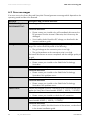
6.3 Error messages
If an error occurs, the Sunny Boy and Sunny Mini Central generate a message which depends on the
operating mode and the error detected.
Message
!PV-Overvoltage!
Description and corrective measure
Overvoltage at DC input.
!DISCONNECT DC!
Corrective measures
• Please contact your installer who will immediately disconnect the
PV generator from the inverter! Otherwise, the inverter may be
damaged.
ACVtgRPro
• Your installer should check the DC voltage, as described in the
inverter installation guide.
The 10-minute-average grid voltage is no longer within the permissible
range. This can be caused by either of the following:
• The grid voltage at the connection point is too high.
• The grid impedance at the connection point is too high.
The inverter disconnects to assure compliance with the voltage quality of
the grid.
Corrective measures
• Please contact your installer or the SMA Solar Technology
Serviceline.
Internal measurement comparison fault or hardware defect.
Corrective measures
Bfr-Srr
• Please contact your installer or the SMA Solar Technology
Serviceline if this problem recurs.
Internal communication fault.
Corrective measures
CAN
Check L-N-PE
Check Varistor
• Please contact your installer or the SMA Solar Technology
Serviceline if this problem recurs.
L and N are swapped on the AC connection or PE is not connected (only
applies for Sunny Mini Central models 9000TL / 1000TL / 11000TL).
Corrective measures
• Please contact your installer to check the AC connection.
At least one of the varistors is defective (only applies to Sunny Mini
Central models 9000TL / 1000TL / 11000TL).
Corrective measures
• Have your installer check the function of the varistors, as described
in the inverter installation guide.
32
SB_SMC-BEN092840
User Manual
SMA Solar Technology AG
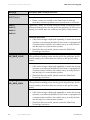
Message
DCBFS-Startup
DC fuse
DCBFS Version
Delta Bfr-Srr
Derating
dFac-Bfr
dFac-Srr
Measurement Channels and Messages
Description and corrective measure
Internal communications fault.
Corrective measures
• Please contact your installer or the SMA Solar Technology
Serviceline if this problem recurs.
At least one of the string fuses is defective (only applies to Sunny Mini
Central models 9000TL / 1000TL / 11000TL).
Corrective measures
• Have your installer check the string fuses and replace them where
necessary. Further information is to be found in the inverter
installation guide.
DC-BFS has been installed with the wrong firmware version.
Corrective measures
• Please contact your installer or the SMA Solar Technology
Serviceline when this problem occurs.
Internal measurement comparison fault or hardware defect.
Corrective measures
• Please contact your installer or the SMA Solar Technology
Serviceline when this problem occurs.
Once the inverter enters the "Derating" mode, it will display the "Derating"
warning until the next total shutdown of the device (at the end of the
day).
Corrective measures
• See Section 3.3.5 "The green LED goes out briefly" (page 14) for
more information on this warning.
Drastic grid frequency fluctuations exceed the permissible range ("Bfr" or
"Srr" are internal messages which are of no relevance to the user).
For safety reasons, the inverter disconnects itself from the grid.
Corrective measures
• Have your installer check the grid frequency and the incidence of
major fluctuations. If repeated frequency variations occur and this
is causing "dFac-Bfr" or ""dFac-Srr" errors, your installer should ask
the utility operator to agree to a modification of the operating
parameters (dFac-Max).
• The installer is responsible for changing the suggested parameters
and making the necessary arrangements with the SMA Solar
Technology Serviceline.
User Manual
SB_SMC-BEN092840
33
Measurement Channels and Messages
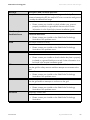
Message
dI-Bfr
SMA Solar Technology AG
Description and corrective measure
The inverter has detected a drastic change in the differential current. This
fault only occurs in transformerless inverters that have no galvanic
isolation from the grid. The integrated differential current monitoring
system plays an important part in ensuring personal safety.
dI-Srr
A drastic change in the differential current can be caused by a sudden
grounding fault, residual current or an actual fault in the device. The
inverter disconnects from the grid.
Corrective measures
dI-Mess-Srr
• If the message „dI-Bfr“ or „dI-Srr“ appears for no obvious reason,
please contact your installer to verify whether the plant insulation
might have a ground fault, as described in the inverter installation
guide.
Deviation in the differential current measurement / differential current
Fault Curr Meas
Corrective measures
• If this fault message is displayed repeatedly, it means that inverter
operation is permanently disabled. If the inverter is equipped with
a communication interface, the installer can try to rectify the fault
with the help of a communication product.
dI-Test
dZac-Bfr
dZac-Srr
• Should this be unsuccessful, please contact the SMA Solar
Technology Serviceline.
Error in differential current measurement.
Corrective measures
• Please contact your installer or the SMA Solar Technology
Serviceline if this problem recurs.
Sudden changes in grid impedance exceed the permissible range ("Bfr"
or "Srr" are internal messages which are of no relevance for the user).
For safety reasons, the inverter disconnects itself from the grid.
Corrective measures
• Have your installer check the grid frequency and the incidence of
major fluctuations. If repeated frequency variations occur and this
is causing „dZac-Bfr“ or „dZac-Srr" errors, your installer should ask
the utility operator to agree to a modification of the operating
parameters (dZac-Max).
• The installer is responsible for changing the suggested parameters
and making the necessary arrangements with the SMA Solar
Technology Serviceline.
34
SB_SMC-BEN092840
User Manual
SMA Solar Technology AG
Message
EEPROM
EEPROM dBh
EeRestore
Fac-Bfr
Fac-Srr
FacFast
Measurement Channels and Messages
Description and corrective measure
Transition disturbance during reading or writing of EEPROM data. This
data is not essential for safe operation.
• The disturbance has no effect on the performance of the inverter.
EEPROM data is defective, the device has switched off because the loss
of data has disabled important functions of the inverter.
Corrective measures
• Please contact your installer or the SMA Solar Technology
Serviceline.
One of the duplicate data sets in the EEPROM is defective and has been
reconstructed without loss of data.
• This error message is for information purposes only and has no
effect on the performance of the inverter.
The grid frequency is no longer within the permissible range ("Bfr" or "Srr"
is an internal message with no relevance for the user). For safety reasons,
the Sunny Boy / Sunny Mini Central disconnects itself from the grid.
Corrective measures
• Please contact your installer to deal with the fault.
HW-Signal
Iac-DC_Offs-Srr
• If the grid frequency is within the tolerance range, yet "Fac-Bfr,"
"Fac-Srr" or "FacFast" faults are still being displayed, please contact
the SMA Solar Technology Serviceline.
Internal measurement fault or hardware defect.
Corrective measures
• Please contact your installer or the SMA Solar Technology
Serviceline if this problem recurs.
The DC component of the electricity being fed into the grid has exceeded
the permissible range. For safety reasons, the inverter disconnects itself
from the grid.
Corrective measures
• If the grid current is outside the permissible range due to local grid
conditions, contact the local utility operator for assistance.
IGBTs
• If the grid current is within the tolerance range, yet the "IacDC_Offs-Srr" fault is still being displayed, please contact the SMA
Solar Technology Serviceline.
The internal hardware monitoring system has detected a fault in the
power electronics.
Corrective measures
• Please contact your installer or the SMA Solar Technology
Serviceline.
User Manual
SB_SMC-BEN092840
35
Measurement Channels and Messages
Message
Imax
SMA Solar Technology AG
Description and corrective measure
Overcurrent on the AC side. This fault code is displayed if the current in
the AC grid is greater than specified.
Corrective measures
• Please contact your installer to have the plant configuration and the
grid conditions checked.
Overcurrent on the DC input side of the Sunny Boy Multi-String. A current
exceeding the maximum permissible value has been detected at the input
of the inverter.
Corrective measures
Imax DC
• Please contact your installer to have the plant configuration
checked.
Fault during relay test.
K1-Close
K1-Open
K2-Open
Corrective measures
Kom DC-BFS
L<->N
L-Netz
L-WR
N-Netz
• Please contact your installer or the SMA Solar Technology
Serviceline when this problem occurs several times in succession.
Internal communication fault.
Corrective measures
• Please contact your installer or the SMA Solar Technology
Serviceline if this problem recurs.
L and N are swapped on the AC connection.
Corrective measures
• Please contact your installer to have the plant checked over.
A grid relay is faulty. The inverter checks the relays connecting it to the
grid before feeding power into the grid. If the grid relays do not function
properly, the inverter does not connect to the grid for safety reasons.
N-WR
Corrective measures
• If this fault message is displayed repeatedly, it means that inverter
operation is permanently disabled. If the inverter is equipped with
a communication interface, the installer can try to rectify the fault
with the help of a communication product.
• Should this be unsuccessful, please contact the SMA Solar
Technology Serviceline.
36
SB_SMC-BEN092840
User Manual
SMA Solar Technology AG
Message
MWE Defect DC
MSD-dI
MSD-FAC
MSD-Vac
MSD-Timeout /
NUW-Timeout
MSD-Zac
Offset
PowerBalance
Measurement Channels and Messages
Description and corrective measure
Internal measurement comparison fault or hardware defect.
Corrective measures
• Please contact your installer or the SMA Solar Technology
Serviceline if this problem recurs.
Internal measurement comparison fault or hardware defect.
Corrective measures
• Please contact your installer or the SMA Solar Technology
Serviceline if this problem recurs.
Internal measurement comparison fault or hardware defect.
Corrective measures
• Please contact your installer or the SMA Solar Technology
Serviceline if this problem recurs.
Internal measurement comparison fault or hardware defect.
Corrective measures
• Please contact your installer or the SMA Solar Technology
Serviceline if this problem recurs.
Internal measurement comparison fault or hardware defect.
Corrective measures
• Please contact your installer or the SMA Solar Technology
Serviceline if this problem recurs.
Internal measurement comparison fault or hardware defect.
Corrective measures
• Please contact your installer or the SMA Solar Technology
Serviceline if this problem recurs.
Fault in the acquisition of measurement data.
Corrective measures
• Please contact your installer or the SMA Solar Technology
Serviceline if this problem recurs.
The Sunny Mini Central is part of a three-phase system with two further
Sunny Mini Centrals. This is equipped with the SMA Power Balancer for
preventing unbalanced loads. The operating parameter "PowerBalancer"
is set to "PhaseGuard" or "FaultGuard".
Corrective measures
• For more detailed descriptions of the operation modes
„PhaseGuard“ and „FaultGuard“ please refer to Section
6.2 "Status Messages" (page 29) under „Balanced“.
User Manual
SB_SMC-BEN092840
37
Measurement Channels and Messages
SMA Solar Technology AG
Message
Rechner /
MSD-Timeout
Description and corrective measure
Functional fault in one of the two microcontrollers.
Corrective measures
Relais 1
• Please contact your installer or the SMA Solar Technology
Serviceline when this problem occurs several times in succession.
A grid relay is faulty. The inverter checks the relays connecting it to the
grid before feeding power into the grid. If the grid relays do not function
properly, the inverter does not connect to the grid for safety reasons.
Relais 2
Relais 3
Relais 4
Corrective measures
• If this fault message is displayed repeatedly, it means that inverter
operation is permanently disabled. If the inverter is equipped with
a communication interface, the installer can try to rectify the fault
with the help of a communication product.
REL_INV_CLOSE
REL_GRID_CLOSE
• Should this be unsuccessful, please contact the SMA Solar
Technology Serviceline.
A grid relay does not close. The inverter checks the relays connecting it
to the grid before feeding power into the grid. If the grid relays do not
function properly, the inverter does not connect to the grid for safety
reasons.
Corrective measures
• If this fault message is displayed repeatedly, it means that inverter
operation is permanently disabled. If the inverter is equipped with
a communication interface, the installer can try to rectify the fault
with the help of a communication product.
REL_INV_OPEN
REL_GRID_OPEN
• Should this be unsuccessful, please contact the SMA Solar
Technology Serviceline.
A grid relay does not open. The inverter checks the relays connecting it
to the grid before feeding power into the grid. If the grid relays do not
function properly, the inverter does not connect to the grid for safety
reasons.
Corrective measures
• If this fault message is displayed repeatedly, it means that inverter
operation is permanently disabled. If the inverter is equipped with
a communication interface, the installer can try to rectify the fault
with the help of a communication product.
• Should this be unsuccessful, please contact the SMA Solar
Technology Serviceline.
38
SB_SMC-BEN092840
User Manual
SMA Solar Technology AG
Message
Riso / Earthfault
Riso-Sense /
Earthfault-Sense
ROM
SD-DI-Wandler
Measurement Channels and Messages
Description and corrective measure
The electrical insulation of the PV system to ground is faulty. The
resistance between the DC plus and/or DC minus connection and ground
is outside the defined limit range.
Corrective measures
• Please contact your installer to check whether your system is
properly insulated or a ground fault has occurred. Further
information is to be found in the inverter installation guide.
The insulation measurement has failed.
Corrective measures
• Please contact your installer or the SMA Solar Technology
Serviceline if this problem recurs.
The inverter firmware is faulty.
Corrective measures
• Please contact your installer or the SMA Solar Technology
Serviceline if this problem recurs.
The inverter has detected an insulation fault on the DC side.
Corrective measures
SD-Imax
• Please contact your installer to check whether the plant is properly
insulated or a ground fault has occurred. Further information is to
be found in the inverter installation guide.
The inverter has detected an overcurrent on the AC side. It disconnects
from the grid for safety reasons and then attempts to reconnect to the
grid.
Corrective measures
SD-WR-Bruecke
• Please contact your installer or the SMA Solar Technology
Serviceline if this problem recurs.
The inverter has detected a fault in the power electronics. It disconnects
from the grid and then attempts to reconnect to the grid.
Corrective measures
Shutdown
• Please contact your installer or the SMA Solar Technology
Serviceline if this problem recurs.
Temporary inverter fault.
Corrective measures
• Please contact your installer or the SMA Solar Technology
Serviceline.
User Manual
SB_SMC-BEN092840
39
Measurement Channels and Messages
Message
STM-Timeout
Trafo-Temp-F
Trafo-Temp-W
SMA Solar Technology AG
Description and corrective measure
Internal program run fault.
Corrective measures
• Please contact your installer or the SMA Solar Technology
Serviceline if this problem recurs.
Temperatures in the transformer have exceeded the acceptable limit. The
inverter stops feeding the grid until the temperature reverts to within the
admissible range.
Corrective measures
• If this problem recurs, check the heat dissipation of the inverter, as
described in Section 5.1 "Checking Heat Dissipation" (page 27).
Temperatures in the transformer have exceeded the acceptable limit. The
inverter stops feeding the grid until the temperature reverts to within the
admissible range. The Trafo-Temp-W warning is displayed until final shutdown (at the end of the day).
Corrective measures
• Check the heat dissipation of the inverter, as described in Section
5.1 "Checking Heat Dissipation" (page 27).
The grid current is no longer within the permissible range ("Bfr" or "Srr" is
an internal message that has no meaning for the user). This can be
caused by any of the following:
Vac-Bfr
Vac-Srr
• Grid disconnected (line circuit breaker, fuse),
• AC cable is broken or
• AC cable is highly resistive
For safety reasons, the inverter disconnects itself from the grid.
Corrective measures
• Please contact your installer to check the grid voltage and the grid
connection at the inverter.
• If the grid voltage is outside the acceptable range due to local grid
conditions, your installer should ask the utility operator whether the
voltage can be adjusted at the feed-in point or whether they would
agree to modifications in the monitored operational limits
(operating parameters: Vac-Min and Vac-Max).
VDiff / UDiff
• If the grid frequency is within the tolerable range, yet "Vac-Bfr," or
"Vac-Srr" faults are still being displayed, please contact the SMA
Solar Technology Serviceline.
Disturbance in the intermediate circuit.
Corrective measures
• Please contact your installer or the SMA Solar Technology
Serviceline if this problem recurs.
40
SB_SMC-BEN092840
User Manual
SMA Solar Technology AG
Message
VpvMax
Measurement Channels and Messages
Description and corrective measure
Overvoltage at DC input.
Vpv-Max
Corrective measures
• Please contact your installer who will immediately disconnect the
PV generator from the inverter! Otherwise, the inverter may be
damaged.
Uzkposneg<10
UZWK-Max
Watchdog
• Have your installer check the plant configuration and the DC
voltage before reconnecting the inverter to the DC voltage.
Disturbance in the intermediate circuit.
Corrective measures
• Please contact your installer or the SMA Solar Technology
Serviceline if this problem recurs.
The internal hardware monitor has detected an overvoltage condition in
the intermediate circuit of the inverter.
Corrective measures
• Please contact your installer or the SMA Solar Technology
Serviceline if this problem recurs.
Internal program run fault.
Watchdog-Srr
Corrective measures
Zac-Bfr
Zac-Srr
• Please contact your installer or the SMA Solar Technology
Serviceline if this problem recurs.
The grid impedance is no longer within the permissible range ("Bfr" or
"Srr" is an internal message that has no meaning for the user). For safety
reasons, the inverter disconnects itself from the grid. The impedance is
calculated from the grid impedance and the impedance of the grid
connection cable (AC cable) of the inverter.
Corrective measures
• Please contact your installer to check the grid impedance and the
grid connection at the inverter. Use a cable with sufficiently large
cross-section (= low impedance), as recommended in the
installation guide. It may also be possible to rectify this fault by
tightening the screws of the AC terminals.
• If this fault recurs, please contact the SMA Solar Technology
Serviceline.
User Manual
SB_SMC-BEN092840
41
Glossary
SMA Solar Technology AG
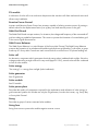
7 Glossary
AC
Abbreviation for "Alternating Current"
DC
Abbreviation for "Direct Current"
Derating
A controlled reduction in performance, usually dependent on component temperatures. Compared
with the (also common) practice of completely shutting down the device, derating has a less drastic
effect on the external grid.
Grid-connected system
PV system which is connected to the power supply grid of an external energy supplier.
Grid impedance
The grid impedance is a characteristic grid specification, which is determined both by the grid
infrastructure, and by the number of power suppliers and power consumers. If supply to the grid
section drops due to a grid shutdown on the part of the adjacent energy suppliers (medium-voltage
transformers), the grid impedance changes abruptly. In order to detect this occurrence, and to prevent
the formation of an unwanted stand-alone grid, SMA Grid Guard monitors the grid impedance and
disconnects the inverter from the grid in the event of a sudden impedance variation.
Inverter
A device for converting the direct current (DC) from the PV generator into alternating current (AC),
which is used by most normal household devices, and especially for feeding energy into an existing
supply grid.
Maximum Power Point "MPP"
The operating point (current / voltage) of the PV generator at which the highest possible performance
under the prevailing conditions is achieved. The actual MPP changes constantly, depending on the
level of solar irradiation, cell temperature, etc.
MPP tracker
A device that adjusts the voltage and current of a PV generator so that it operates at its
"Maximum Power Point".
PV
Abbreviation for "photovoltaic" describing the conversion of solar energy into electrical energy.
PV generator
Technical device for the conversion of solar energy into electrical energy. This normally refers to all
installed and electrically connected solar modules in a PV system.
42
SB_SMC-BEN092840
User Manual
SMA Solar Technology AG
Glossary
PV module
A collection of solar cells in an enclosure that protects the sensitive cells from mechanical stress and
allows easy installation.
Reactive Power Control
Inverters with Reactive Power Control are inverters capable of utilizing reactive power. By setting a
default value for the displacement factor (cos ϕ) they can feed reactive power to the grid.
SMA Grid Guard
The SMA Grid Guard concept monitors, for instance, the voltage and frequency of the connected AC
grid according to predefined parameters. This serves to prevent the formation of a stand-alone grid
in the event of grid disconnection.
SMA Power Balancer
The SMA Power Balancer is a serial feature of the Sunny Mini Central. The SMA Power Balancer
prevents the formation of an unbalanced load during three-phase grid feeding. To this effect, a group
made up of 3 Sunny Mini Centrals are each connected via a control line to a 3-phase feeding unit.
Solar cell
An electronic component which generates electrical energy when irradiated with sunlight. Since the
voltage produced by a single solar cell is very small (approx. 0.5 V), several solar cells are combined
to form a solar module.
Solar energy
"Sun energy", i.e. energy from sunlight (solar irradiation).
Solar generator
See PV generator
Solar module
See PV module.
Solar power plant
Describes the totality of components required for the exploitation and utilization of solar energy. In
grid-connected systems this includes not only the PV generator, but also the inverter, e.g. Sunny Boy
or Sunny Mini Central.
String
Describes a group of series-connected solar modules.
String fuse
String fuses serve to protect the modules against reverse current.
User Manual
SB_SMC-BEN092840
43
Glossary
SMA Solar Technology AG
String inverter
In string technology, the PV generator is subdivided into individual module surfaces, or "strings", each
of which has an assigned string inverter. This technology reduces system costs while at the same time
making installation a lot simpler and increasing the energy yield and system availability.
Unbalanced load
The difference between the power fed into the grid at the individual phase conductors. In Germany,
it is not permitted to exceed a nominal output of 4.6 kVA (plus 10 % overload, i.e. 5 kVA in total).
Varistor
In the Sunny Boy and Sunny Mini Central, varistors protect the electronics from atmospherically
coupled energy peaks, such as those that can occur in the conductor loop of the PV generator in the
event of nearby lightning strikes. They limit overvoltage by discharging the coupled current to earth.
During operation, varistors are subject to a certain degree of ageing. Varistors which have been in
service for a long time or have already had to discharge overvoltages, are subject to a decrease in
internal resistance and heat up significantly. Thermally monitored varistors recognize this increased
temperature and automatically disconnect from the power circuit. If the protective function of the
varistor is no longer given, the inverter triggers a fault message.
44
SB_SMC-BEN092840
User Manual
SMA Solar Technology AG
Contact
8 Contact
If you have technical problems concerning our products, please contact our Serviceline. We require
the following information in order to provide you with the necessary assistance:
• Inverter type
• Communication method
• Type and number of modules connected
• Serial number of inverter
• Blink code or message displayed by the inverter
SMA Solar Technology AG
Sonnenallee 1
34266 Niestetal, Germany
www.SMA.de
Serviceline
Inverters:
+49 561 9522 1499
Communication:
+49 561 9522 2499
Fax:
+49 561 9522 4699
E-mail:
[email protected]
User Manual
SB_SMC-BEN092840
45
Contact
46
SMA Solar Technology AG
SB_SMC-BEN092840
User Manual
SMA Solar Technology AG
Legal Restrictions
The information contained in this document is the property of SMA Solar Technology AG. Publishing its content, either partially or
in full, requires the written permission of SMA Solar Technology AG. Any internal company copying of the document for the
purposes of evaluating the product or its correct implementation is allowed and does not require permission.
Exclusion of liability
The general terms and conditions of delivery of SMA Solar Technology AG shall apply.
The content of these documents is continually checked and amended, where necessary. However, discrepancies cannot be
excluded. No guarantee is made for the completeness of these documents. The latest version is available online at www.SMA.de
or from the usual sales channels.
Guarantee or liability claims for damages of any kind are excluded if they are caused by one or more of the following:
• Damages during transportation
• Improper or inappropriate use of the product
• Operating the product in an unintended environment
• Operating the product whilst ignoring relevant, statutory safety regulations in the deployment location
• Ignoring safety warnings and instructions contained in all documents relevant to the product
• Operating the product under incorrect safety or protection conditions
• Altering the product or supplied software without authority
• The product malfunctions due to operating attached or neighboring devices beyond statutory limit values
• In case of unforeseen calamity or force majeure
The use of supplied software produced by SMA Solar Technology AG is subject to the following conditions:
• SMA Solar Technology AG rejects any liability for direct or indirect damages arising from the use of software developed by
SMA Solar Technology AG. This also applies to the provision or non-provision of support activities.
• Supplied software not developed by SMA Solar Technology AG is subject to the respective licensing and liability agreements
of the manufacturer.
SMA Factory Warranty
The current guarantee conditions come enclosed with your device. These are also available online at www.SMA.de and can be
downloaded or are available on paper from the usual sales channels if required.
Trademarks
All trademarks are recognized even if these are not marked separately. Missing designations do not mean that a product or brand
is not a registered trademark.
The Bluetooth® word mark and logos are registered trademarks owned by Bluetooth SIG, Inc. and any use of such marks by SMA
Solar Technology is under license.
SMA Solar Technology AG
Sonnenallee 1
34266 Niestetal
Germany
Tel. +49 561 9522-0
Fax +49 561 9522-100
www.SMA.de
E-Mail: [email protected]
© 2004 to 2009 SMA Solar Technology AG. All rights reserved
User Manual
SB_SMC-BEN092840
47
SMA Solar Technology AG
www.SMA.de