1
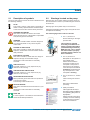
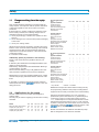
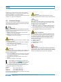
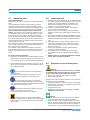
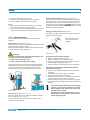
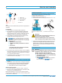
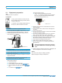
Operation manual WIWA PROFIT Version: ❍ Airless ❍ Air-Combi ❍ Hot Job Type: ❍ 3010 ❍ 3022 ❍ 3033 ❍ 4210 ❍ 4222 ❍ 4233 Serial-No. …………………… Translation of original operation manual Profit · DBK · en · 02.12 · jw Contents 1.2 1 Table of contents 1.2 Preface 1 1.1 1.2 Contents Table of contents Preface 2 2.1 2.2 2.3 2.4 2.5 2.6 2.7 2.8 2.9 2.10 2.11 2.12 Safety Description of symbols Warnings located on the pump Dangers arising from the equipment Applications for the pump Pump surroundings Sources of danger Operating staff Installation site Behavior in case of emergency Safety features Pump handling and auxiliary materials Transporting 4 4 4 5 5 6 7 8 8 8 9 10 10 3 Component description 11 4 Erection and Assembly 12 Manufacturer’s notes and operating guidelines for coating and pumping materials should be observed at all times. 5 5.1 5.2 Start-up First cleaning Pressure check 14 14 15 No method of operation should be exercised which impairs the safety of WIWA products and the operating personnel. 6 6.1 6.2 6.3 Operation Equipment preparation Spray operaton Change of material 16 16 17 17 7 Shutting down 18 8 8.1 8.2 Optional versions Air Combi Hot Job 19 19 20 9 9.1 9.2 9.3 Maintenance Regular inspections Maintenance plan High pressure filter 21 21 21 21 10 Malfunctions and troubleshooting 23 11 11.1 11.2 11.3 Appendix Technical specifications Auxiliary materials Machine card 24 24 25 25 Page 3 3 3 This User’s Handbook must always be available to operating staff! The operating authority of the equipment must ensure, that a User`s Handbook is available to the operator, in a language which he understands! Dear customer! Thank you for your decision to purchase equipment. In the User’s Handbook, you can find all information required for the proper handling of your PROFIT. However, for safe operation, there are further essential details which you should adhere to: Please read and observe the guidlines valid for your country. In Germany, the "Richtlinien für Flüssigkeitsstrahler" (Guidelines for fluid sprayers) published by: Hauptverband der Gewerblichen Berufsgenossenschaften (Industrial Employer's Liability Insurance Association), are valid. We wish you much success and excellent working results when appliying your PROFIT. WIWA Wilhelm Wagner GmbH & Co.KG. Copyright © 2009 WIWA Copyright ownership for this user manual remains with WIWA WILHELM WAGNER GmbH & Co. KG Gewerbestraße 1-3 • 35633 Lahnau Phone: +49 (0)6441 609-0 • Fax: +49 (0)6441 609-50 • E-mail: [email protected] • Internet: www.wiwa.de This operating manual is solely intended for personnel involved in preparation, operation and servicing. It is prohibited to pass on this operating manual for reproduction, utilisation or communication of its contents, unless this has been explicitly permitted. Infringements incur an obligation to pay damage compensation. All rights reserved in the event of registration of the patented design, industrial design or registered design. This operating manual only applies in conjunction with the machine card that was given to you with the user manual for your equipment. Please check that the type plate data is identical with the information on the machine card. Please notify us immediately if there are discrepancies, if the user manual has been incorrectly compiled or if the type plate is missing. Translation of the original operation manual Airless Profit AA001 • en • 01.10 3 2 2.1 Safety Description of symbols The signs and symbols used in this User's Handbook have the following meaning: NOTE This marks a section of text which is especially relevant to safety. Special attention should be paid to this section and the contents strictly observed. SMOKING PROHIBITED This marks a situation in which a fire hazard arises through the use of flammable or explodable solid, fluid or gaseous materials. WARNING This marks a situation which could be dangerous. If not observed,death or very serious injuries could result. DANGER OF EXPLOSION This marks a situation, where there is danger of explosion. Observation of this information is absolutely essential. ELECTRICAL VOLTAGE This marks a situation, where there is a danger of explosion through an electostatic charge. Observation of this information is absolutely essential. 2.2 Warnings located on the pump Warning signs and symbols which have been placed on the unit are there to inform of possible dangers and must be observed. Warning signs and symbols may not be removed. Damaged and illegible warning signs and symbols are to be replaced immediately. The following signs are located on the unit: ➤➤ Pos. 1, Picture 2.2.1 Ground warning on the highpressure filter 3 l 1 l l 2 Picture 2.2.1 USE EAR PLUGS For health reasons, it is very important to pay attention to this warning. USE BREATHING PROTECTION For health reasons, it is very important to pay attention to this warning. WEAR PROTECTIVE GLOVES Wear protective gloves with lower arm protection to avoid burn injuries. The warnings must be adhered to. HEALTH DANGER This marks materials which are hazardous to your health. Observation of this information is absolutely essential. The propietor is required according to the German Accident Prevention Regulation (Unfallverhütungsvorschrift), BGR 500, Kap. 2.29, to ensure that the machine is properly grounded. Please, observe our User's Handbook. ➤➤ Pos. 2, Picture 2.2.1 Nameplate on the cylinder of the material pump Please observe that the information located on the nameplate corresponds to data found on the machine card. We request immediate notification should there be any discrepancies or if the nameplate is missing. ➤➤ Pos. 3, Picture 2.2.1; Picture 2.2.2 Label covering anti-vacuum hole Picture 2.2.2 Remove this label before operating! ➤➤ Safety information This sign lists the most important safety guidlines for operating this piece of equipment. FIRST AID In case of injuries or accidents, these instructions should be absolutely adhered to. Please read this information carefully as well as adhering to all instructions located in this User's Handbook! Picture 2.2.3 4 Translation of the original operation manual Airless Profit AA001 • en • 01.10 Safety 2.3 2 ������������������������������� Dangers arising from the equipment Airless applications Model This unit was designed and built in accordance with all safety aspects. It corresponds with the present standards of technical regulations and current rules for accident prevention. It left the factory in perfect condition and warrants a high level of safety. However, the following dangers exist if operated incorrectly or used inappropriately: ➤➤ risk of physical injury or death to the operator or third persons ➤➤ risk of damage to the unit and other property belonging to the owner ➤➤ risk of poor coating results All personnel involved in the starting, operation and maintenance of the unit must read the following notes carefully and observe them. We recommend that the managers responsible for the proper operation of the unit have this confirmed in writing. It is a matter of their safety! Additionally, please pay attention to the following: Please, read and observe the guidlines valid for your country. In Germany the "Richtlinien für Flüssigkeitsstrahler" (Guidelines for liquid sprayers) Published by: Hauptverband der Gewerblichen Berufsgenossenschaften, are valid. We recommend adding a copy of all guidelines and accident prevention regulations into the User's Handbook. Manufacturer’s notes and operating guidelines for coating material and pumping material should be observed at all times. In principle, no method of working should be exercised which impairs the safety of products or the operating personnel. 2.4 Applications for the pump 3033 4210 4222 3.0 14 .22 .47 4.2 27 .43 .91 Typical coatings Oil and grease High-build varnish Primer Sprayable spackle Sprayable paint and lacquer Plural component material Textured paint Hammer-tone paint Water soluble coating Waterbourne lacquer Air Combi applications Model Typical industries Carpentry shops Furniture industry Paint and finishing shops Machine and vehicle manufacture Typical coatings Oil and grease High-build varnish Primer Sprayable spackle Sprayable paint and lacquer Plural component material Textured paint Hammer-tone paint Water soluble coating Waterbourne lacquer • very suitable 4222 4233 • ° – – • ° – – • • ° – • • ° ° ° – ° – • ° – – ° ° • • • ° • ° • • • ° ° – • – • ° – ° ° ° • • • ° • ° • • • • 3010 3022 3033 4210 4222 4233 • ° – – • ° – – • ° – – • ° ° ° • ° ° ° • • ° ° ° • • – • – • • • • • • • – • – • • • • • • • – • – • • • • ° • • – • – • • • • • • • – • – • • • • • • • – • ° • • • • ° suitable – unsuitable 4.2 27 .43 .91 4233 4.2 27 .43 .91 Dangerous chemical reactions can occur if closed or pressurized systems with aluminum or galvanized pump components come into contact with solvents such as 1.1.1 - trichlorethylene or methylene chloride that contain halogenated chlorofluorocarbons (CFC). If such solvents, or paints or lacqures that contain them, are to be used, we recommend contacting Customer Service or the factory directly for further information. Please note that there are stainless-steel Airless pumps that are designed for use with such materials. Translation of the original operation manual Airless Profit AA001 • en • 01.10 3033 4210 Waterbourne lacquer and water soluble coating can only be sprayed using stainless-steel pumps. Existing Airless equipment can be easily converted for Air Combi finishing. PROFIT series pumps are portable and designed for spraying paint. The may only be used for applying paint and other coating materials. Model 3010 3022 Max. free-flow output (l/min.) 3.0 3.0 Output per cycle (ccm) 14 14 Output at 60 cpm (gal./min.) .22 .22 Output per cycle (fl.oz.) .47 .47 3010 3022 Typical industries Carpentry shops Furniture industry Paint and finishing shops Machine and vehicle manufacture 5 2 Safety Using this equipment in areas requiring explosion protection: Marking: II 2G cT4 This equipment fulfills the explosion-proof requirements found in the guideline 94/9/EC for the type of explosion, equipment catagory and temperature class found on the nameplate. This equipment is able to be installed in areas requiring Zone I explosion protection. Due to the possibility that explosive gases and overspray may be created, this unit is to be considered as Group II, Equipment Catagory 2G. The flash point for the materials being sprayed, as well as the solvent being used, must be above 200°C. When operating this equipment, the User‘s Handbook must be followed closely. The required inspection and maintenance intervals must be adhered to strictly. All information found on the unit‘s signs or plates must be adhered to and not exceeded. Do not allow this unit to be overloaded. It is the responsibility of the operator of this equipment to determine the explosion risk (zone determination according to EC regulation 94/9/EC, Appendix II, Nr. 2.1-2.3) in the area of usage, in accordance with local regulatory authority guidelines. Furthermore, it is the responsibility of the operator on-sight to check and ensure that the technical specifications and markings according to ATEX are compliant with local requirements. Please observe that some components have their own nameplate with separate markings according to ATEX. The marking with the lowest rating for explosion protection becomes valid for the entire system. If the intended application could lead to injury of personnel if this equipment malfunctions, on-sight precautions and preventive measures must be implemented. If this equipment appears to be malfunctioning, the unit must be shut down immediately and Customer Service contacted as soon as possible. k It must be ensured that the pump is grounded separately or together with the equipment it is mounted to (maximum resistance 106 Ω, picture 2.4.1 ground / potential equalization). Picture 2.4.1 Grounding screw on the high-pressure filter 6 Equipment that is not rated as explosion-proof may not be operated in areas requiring explosio-proof protection. Pneumatically driven Airless spraying equipment is not effected by this. If, however, agitators, heaters or other electrical accessories are used, they must first be checked for their explosion-proof rating. Plugs for heaters, agitators, etc. may only be connected to sockets outside of the explosion-proof area, even if the unit itself is rated as explosion-proof. Other usage is not in line with regulations. Before equipment is used for other purposes or with other materials, and, therefore, not according to the regulations, permission should be obtained from the manufacturer as the guarantee is otherwise invalid. The observation of technical documentation and the compliance with specified operational, maintenance and starting guidelines are manditory in accordance with the valid regulations. 2.5 Pump surroundings Rebuilds and modifications For safety reasons, it is not allowed to carry out rebuilds or changes without authorization. Protective equipment may not be dismounted, changed or neglected. If using components which are not produced or delivered by , warranty coverage is negated as well as liability. The machine may only be operated within the prescribed limits and machine parameters. Danger caused by accessories and spare parts If you use original attachments and original spare parts from , the compatability with our equipment is guaranteed. It is, however, essential that the safety regulations of the attachments and spare parts are observed. You can find these safety regulations in the User’s Handbook located with the spare parts lists. If you use attachments and spare parts from another source, cannot guarantee the safety of the entire system. In this case, our guarantee does not cover any damage or injury caused by such attachments and spare parts. Emissions It is possible for solvent vapours to occur, depending on the materials used. Therefore, please ensure the workplace is sufficiently ventilated in order to avoid damage to health and property. Always observe the processing information given by the material manufacturer. The sound pressure level of the equipment is below 85 db(A). The operator is responsible for compliance with the rules covering the prevention of accidents due to „noise“ (BGV B3). Translation of the original operation manual Airless Profit AA001 • en • 01.10 Safety 2 Therefore, pay special attention to the environmental conditions at the site, e. g. noise can be increased if the machine is installed in or on hollow bodies. Exact specifications covering noise emissions are found in Chapter 10.1 Technical specifications. 2.6 Sources of danger Always remember, plural component systems operate at very high pressure levels and unauthorized usage could lead to life-threatening injuries. Warning! Material exits the spray gun at very high pressure levels. The spray jet can cut or be injected under the skin or eyes, resulting in serious injuries. ➤➤ Never point the spray gun towards yourself, other people or other living creatures. ➤➤ Never hold your finger or hand in front of the spray gun and never reach into the spray jet. Warnung! Unintentional triggering of the spray gun can lead to injury or damage to property. ➤➤ Always apply the spray gun safety catch, regardless how short the pause in spraying is. ➤➤ Before operation, always check the function of the spray gun safety catch. Warnung! Components that do not correspond to the maximum pressure created by the pump are quickly prone to rupture, leading to serious injuries. ➤➤ Fluid hoses must be rated to correspond to the maximum operating pressure of the unit, with an appropriate safety factor allowance. ➤➤ No hoses may show signs of leaks, kinks, wear or blisters ➤➤ All hose connections must be tight Warning! If used outdoors, a lightning strike could lead to injury. ➤➤ Never operate the unit outdoors during a thunderstorm. Warning! It is possible for a static charge to occur due to the high flow speeds during the airless spraying procedure. Static charges can lead to fire and explosions. ➤➤ Always use an open container. ➤➤ Never spray solvents or materials containing solvents into narrow-necked cans or barrels with bung holes! ➤➤ Ensure that the spray gun has contact with the container walls when working with metal containers. Danger of explosion! Heated solvent can lead to an explosion within the pump. This could result in serious injuries, including loss of vision, and property damage. Always observe the flashpoint and ignition temperature for the solvent being used! Turn off the fluid heater whenever the following work is performed on the pump: ➤➤ Flushing / Cleaning ➤➤ Pressure check ➤➤ Preparation for operation ➤➤ Shutting down Danger! If being operated in closed rooms, explosive atmospheres can be created. This could lead to serious injuries and property damage. Smoking, using open fires or other ignitable sources is prohibited in the entire area of operation! The maximum operating pressure stated by us must correspond to all components and accessory items within the system (i.e. pumps, heaters, hoses, spray guns, safety valves). If the pressure ratings differ, the lowest rated max. pressure becomes valid for the entire system. Example: Pump max. 420 bar (6090 psi) Fluid hose max. 600 bar (8700 psi) Spray gun max. 500 bar (7250 psi) The maximum allowable operation pressure for the entire system is 420 bar (6090 psi). Translation of the original operation manual Airless Profit AA001 • en • 01.10 7 2 Safety 2.7 Operating staff Authorised Operators People under the age of 16 should not operate this equipment. The management in charge of the operation of the machine must make the User’s Handbook available to the operator and must make sure that he has read and understood it. Only then may the system be put into operation. We recommend the manager has this confirmed in writing. The operator of the machine is obliged to report any changes in the machine which might affect its safety to the manager, as he must ensure that the machine is functional. The responsibilities for the different activities on the system must be laid down clearly and adhered to. No unclear competences may remain as these could endanger the safety of the users. The operator must make sure that only authorised persons work on the machine. He is responsible to third parties in the working vicinity of the system. The operator of the equipment is obliged to repeat instructions about dangers and safety measures at regular intervals (at least once a year, for young persons twice a year). Personal protective equipment ➤➤ We call to your attention that the valid guidelines and requirements in accordance with work surroundings (mining, closed areas etc.) must be absolutely adhered to. ➤➤ The prescribed protective clothing must be worn at all times, as solvent vapours and solvent splashes cannot be completely avoided ➤➤ The sound pressure level of the equipment is below 85 db(A). Nevertheless, appropriate noise protection means should be made available to the operating staff. ➤➤ Although spraying fog is kept to a minimum when the correct pressure setting and proper method of operation are observed, the operating painter should wear a protective breathing mask. ➤➤ When working with heated materials, the outer surface of the pump can become hot. Protective gloves must be worn at all times. ➤➤ Never use solvent or other materials which present a health hazard for cleaning skin. Only suitable skin protective, skin cleansing and skin care materials may be used. 8 2.8 Installation site 2.9 Behavior in case of emergency ➤➤ High-pressure spray equipment can be installed inside or outside of spray booths and spray rooms. To avoid pollution, an outside installation is preferable. The dimensions and weight of the unit can be found in Chapter 10.1 Technical specifications. ➤➤ The unit must have a fixed position and sufficient space to ensure safe operating. ➤➤ Keep the area you are working in clean, especially walkways. Remove any spilled paint or solvent immediately. ➤➤ Ensure that sufficient ventilation is available to avoid any injuries or damage to equipment. Always follow the handling instructions givin by the materials manufacturer. ➤➤ Although there are no laws governing the low overspray airless spraying method, dangerous solvent fumes and paint particles need to be suctioned and filtered out of the air. ➤➤ Protect any neighboring objects against damage caused by possible overspray. ➤➤ The operator of this equipment must ensure that the complete system is protected against lightening strikes. ➤➤ Adhere closely to all relevant guidelines covering safety and/or accident prevention. Leaks Warning! If leaks occur in hoses or hose connections, material is expelled under very high pressure. This can result in very serious injuries to hands, arms or eyes. ➤➤ Never try to seal leaks with hands or by bining ➤➤ Never patch fluid hoses. Should a leak occur, the whole system is to be shut down and depressurized immediately: ➤➤ Close the air tap lock to cut off the inbound air supply. ➤➤ Hold the drain hose into an appropriate container and ensure that it can not slip. ➤➤ Open the drain valve. ➤➤ Replace the defective parts immediately or contact WIWA Customer Service. Injuries ➤➤ Should an injury occur (i.e. spray jet cut or injection), we recommend a doctor be called immediately. ➤➤ Inform the doctor of the material sprayed (e.g. paint) and the solvent (thinner).Have the product data sheet at hand (adress and telephone number of supplier or manufacturer, name of material and material number). Translation of the original operation manual Airless Profit AA001 • en • 01.10 Safety 2 ➤➤ Memorize where aid can be found. ➤➤ Memorize the local emergency phone numbers. ➤➤ Become familier with the first-aid measures Fires ➤➤ Read and and observe the instructions for fire alarm and escape routes put up in your factory. ➤➤ Do not use any other extinguishing agents than those which are prescribed by the coatings manufacturer. 2.10 Safety features Ground cable connection (Picture 2.10.2, Pos. 1) Due to the high flow speed created by Airless equipment, static charging can occur. A static charge can lead to fires or explosion. The unit must, therefore, always be grounded properly. Factory-delivered Airless spraying equipment comes standared with a ground cable. If lost or defective, it must be replaced. Spray gun safety catch (Picture 2.10.3) The spray gun safety catch is used to avoid unintentional triggering of the spray gun. Apply the safety catch ("on") at any pause in spraying! This equipment is delivered with the following safety features: Safety valve (Picture 2.10.1, Pos. 1) The safety valve prohibits the maximum allowable inbound air pressure from being exceeded. If the inbound air pressure exceeds the maximum allowable value, the safety valve will blow off. Warning! The safety valve is factory mounted and sealed to the air motor. To ensure safe operation: ➤➤ Never remove the safety valve. ➤➤ Never change the safety valve setting. New safety valves must correspond to the maximum allowable inbound air pressure and be sealed appropriately. The part number and maximum allowable inbound air pressure can be found in the machine card for the unit. 2 1 1 Picture 2.10.1 Picture 2.10.2 Air tap lock (Picture 2.10.1, Pos. 2) The compressed air tap lock makes it possible to shut Air tap lock (Picture 2.10.1, Pos. 2) The compressed air tap lock makes it possible to shut down the unit immediately. Picture 2.10.3 All safety devices must be checked: ➤➤ Before commissioning the system! ➤➤ Before beginning to work with the system! ➤➤ After any modifications have been made to the unit! ➤➤ After flushing or cleaning the system! ➤➤ After any repair or maintenance work on the system! Checklist for checking the safety devices with the system depressurized ➤➤ Check to see whether the seal on the safety valve is damaged. ➤➤ Check the safety valve for signs of damage. ➤➤ Check the ground cable for damage. ➤➤ Check the connctions for the ground cable on the unit and the conductive object it is connected to. ➤➤ Check whether the air tap lock is functioning properly. ➤➤ Check the spray gun safety catch to ensure it functons properly. If one of the safety devices is not functioning properly or if any other malfunction is found, the air supply to the unit must be cut off and the drain valve opened. The unit may only be restarted once the problem has been solved and the system is functioning perfectly again. Translation of the original operation manual Airless Profit AA001 • en • 01.10 9 2 Safety 2.11 ��������������������������������� Pump handling and auxiliary materials Adjusting, servicing, cleaning, maintenance and repair of the unit ➤➤ Before starting any of the above: ➤➤ Turn off the unit ➤➤ Depressurize the system. Pay attention to residual pressure. Activity Personnel Qualification Adjusting work trained operator Servicing work trained operator Cleaning work trained operator Maintenance work personnel trained by WIWA Customer service Repair work personnel trained by WIWA Customer service ➤➤ Any components or accessories that had to be removed for transport must be remounted by skilled and trained personnel before beginning operation ➤➤ l For transporting the pump, a handle is mounted on the upper housing of the air motor (Picture 2.12.1). Picture 2.121 ➤➤ After work is completed ➤➤ Check the proper function of all safety features. ➤➤ Check the proper function of the entire unit. Handling of auxiliary materials ➤➤ When handling auxillary materials such as paint, solvent, oil, grease and other chemical substances, comply with the safety and dosing instructions of the manufacturer and the generally applicable regulations. ➤➤ Leftover solvents, oils, grease and other chemical substances must be collected according to the legal regulations for recycling and waste disposal. ➤➤ The local official laws for the protection of waste water must be observed. 2.12 Transporting ➤➤ Disconnect the unit from the main air supply and from any electrical outlets for accessory items, even if the unit is only to me moved a short distance. ➤➤ Empty the unit before transporting. ➤➤ Be careful when using a hoist to load this equipment! ➤➤ If using a hoist, ensure that the weight capacity is not exceeded and that proper lifting attachments are employed. ➤➤ Attach the hoist securely to the unit. ➤➤ Never stand under or near the unit when it is suspended. Serious injury could result! ➤➤ Only use appropriate hoisting equipment with sufficient load capacity. ➤➤ Secure the unit to the transporting vehicle in such a way that it can not slide or fall off. ➤➤ When lifting or loading the unit, do not transport any further items (i.e. paint cans or pails) along with it. 10 Translation of the original operation manual Airless Profit AA001 • en • 01.10 Component description 3 4 5 Components 2 1 Cart frame 2 Handle for transport 12 11 10 13 4 Air pressure regulator 7 5 Air tap lock (rotated view) 6 Compressed air connection 1 14 15 3 Air motor 3 6 7 Safety valve 8 Pressure gauge 9 Material pump 10 High-pressure filter 8 (rotated view) 3 9 10 11 Drain valve 12 Drain hose 13 Release agent filling tube 14 Release agent drain screw 15 Connection for spray hose 16 Suction pipe with strainer 16 PROFIT - pail version PROFIT - tripod version PROFIT - cart version PROFIT - wall version PROFIT - funnel version PROFIT - funnel version, Serial .../K Translation of the original operation manual Airless Profit��� 11 AA001 • en • 01.10 4 Erection and Assembly 1 3 2 4 1 2 3 4 Airless unit Airless spray gun Paint container Spray hose 2. Mount accessories For transport purposes the following components were dismounted and packed in a separate carton: 1. Spray hose (Picture 4.1.2) 2. Airless spray gun (Picture 4.1.3) ➤➤ Attach these items according to Picture 4.1.2 + 4.1.3. Picure 4.1.1 Job The unit is to be installed at the job site and prepared for operation. Prerequisite ➤➤ The material to be worked with is prepared. ➤➤ All materials to be sprayed should be marked with information on viscosity, processing temperatures, mixing proportions etc. If this is not the case, please acquire this data from the relevant manufacturer. ➤➤ The material to be sprayed must be slowly but thoroughly stirred before beginning to work. offers a broad selection of accessories for the optimised preparation of spraying materials, i.e.: ➤➤ agitators in various sizes ➤➤ material pre-heating containers in various sizes ➤➤ fluid hester If working with plural component materials, the pot life must be observed. ➤➤ To insure that the necessary volume of air is supplied, the compressor capacity must comply with the air consumption requirements of the pump (refer to Chapter 10.1 Technical specifications). ➤➤ The diameter of the air supply hoses must correspond to the connection on the pump. 1. Set up the pump ➤➤ The pump must be set up securely on a level and solid surface ➤➤ Pay attention to the information covering the required floor space found in Chapter Technical specifications ➤➤ Operating elements must be easily accessible ➤➤ Safety features must be easily accessible m m Picture 4.1.2 Spray hose connection on the high-pressure filter Picture 4.1.3 Spray hose connection to the spray gun Warning! Material leaks at connections can lead to serious injury of property damage. Check all turnable parts, nuts, screws and hose connections and tighten them securely. ➤➤ Check the permissible maximum air pressure for the spray hose, spray gun and accessories. It must be greater than or equal to the maximum operational pressure shown on the pump's nameplate or on the machine card. 3. Ground the unit Warning! Due to the high flow speed created by Airless equipment, static charging can occur. A static charge can lead to fires or explosion A static charge can lead to fires or explosion. ➤➤ The pump and object to be coated must be grounded properly ➤➤ Only use conductive hoses Note: spray hoses are conductive and compatible with pumps Wall-mounted versions: ➤➤ To fix the wall-mount, use M 12 screws - class 8.8 ➤➤ Be sure to use anchoring devices in accordance with the nature of the wall being used Ensure that at least 10 cm (4 in.) free space is left between the suction elbow and the floor after mounting (refer to the picture in Chapter 3) 12 Translation of the original operation manual Airless Profit AA001 • en • 01.10 Erection and Assembly 4 4. Open the anti-vacuum hole ➤➤ Remove the label "Peel off before use" from the antivacuum hole. (Picture 4.1.4, Pos. 2) 5. Check the release agent level ➤➤ Check the level of release agent - refer to Chapter 8.2 2 m 1 i Picture 4.1.4 Result The unit is now ready for operation. Translation of the original operation manual Airless Profit��� 13 AA001 • en • 01.10 5 Start-up 5.1 First cleaning Job This machine was factory tested after assembly for perfect functioning with a test-medium. The entire system should be flushed with wash thinner before spray operation begins so that the material to be sprayed is not affected by the test-medium. Adjusting the air pressure regulator: Unlock: Pull the control knob upwards Lock: Push the control knob downward ➤➤ Connect the air supply line to the inbound air connection (Picture 5.1.2, Pos. 3) Prerequisite Required: 1 open container with cleaning material (at least 5 liters / 1.3 gal. of wash thinner or solvent), called container "A" below. 2 1 1 empty, open container for the mixture of cleaning material and test-medium, called container "B" below. Procedure 1. Prepare the spray gun for operation ➤➤ Close and apply the safety catch. ➤➤ Remove the tip from the spray gun. Observe and follow the instructions found in the spray gun's User's Handbook. 2. Prepare the solvent container ➤➤ Place the suction pipe with strainer into the "A" container. Pail-mounted versions: ➤➤ Unlock the pail lid from the pail ➤➤ Remove the pump from the pail ➤➤ Place the container "A" into the empty pail ➤➤ Place the pump back onto the pail and lock down accordingly Funnel-mounted versions: ➤➤ Fill the funnel with solvent. Series …/K: To fill the material pumps and bleed the unit, press the bleed assist under the feed funnel while filling (Picture 5.1.1). 3 Picture 5.1.2 4. Clean the high-pressure filter ➤➤ Hold the drain hose (Picture 5.1.3, Pos. 2) into the container "B" and secure against slipping. ➤➤ Open the drain valve (Picture 5.1.3, Pos. 1) or drain screw (Picture 5.1.4, Pos. 1) ➤➤ Open the air tap lock. (Picture 5.1.2, Pos. 1) ➤➤ Adjust the air pressure regulator (Picture 5.1.2, Pos. 2) until the pump runs slowly (maximum 2 bar / 30 psi). ➤➤ Allow solvent (soiled with test-medium) to be pumped into container "B" for at least 10 seconds. ➤➤ Close the drain valve (Picture 5.1.3, Pos. 1) or tighten the drain screw (Picture 5.1.4, Pos. 1) securely. 1 2 1 Picture 5.1.2 High-pressure filter with drain valve Picture 5.1.1 3. Connect the compressed air line ➤➤ Close the air tap lock (Picture 5.1.2. Pos. 1). ➤➤ Turn the control knob on the air pressure regulator counter-clockwise until it turns freely (Picture 5.1.2, Pos. 2). 14 Picture 5.1.3 High-pressure filter with drain screw Recommended cleaning time max. 2 bar (30 psi) min. 10 seconds Translation of the original operation manual Airless Profit AA001 • en • 01.10 Start-up 5 5. Clean the spray gun ➤➤ Hold the spray gun into container "B". ➤➤ Spray for a minimum of 10 seconds against the inner wall of the container. Ensure that the spray gun has contact with the container walls when working with metal containers ➤➤ ➤➤ ➤➤ ➤➤ Result The unit is now completely clean. Continue with the pressure check (Chapter 5.2). ➤➤ ➤➤ ➤➤ Funnel-mounted versions: ➤➤ Pump the solvent out of the funnel until it is empty. ➤➤ 5.2 Pressure check Job Check the seal of all system components. Procedure 1. Close the spray gun ➤➤ Close the spray gun and apply the safety catch. Hold the spray gun into container "B". Disengage the safety catch and open the spray gun. Pump any remaining solvent out of the system. Turn the air pressure regulator control knob counterclockwise until it turns freely. Close the air tap lock. Close the spray gun and apply the safety catch. Hold the drain hose into container "B" and secure it against slipping. Depressurize the pump by briefly opening the drain valve / drain screw on the high-pressure filter. Result The unit is now ready for operation. 2. Set the maximum pressure ➤➤ Set the maximum allowable pressure by turning the air pressure regulator control knob clockwise (Picture 5.1.2). Observe the maximum allowable operating pressure for all system components. If the ratings vary, the lowest pressure rating becomes the maximum allowable pressure for the entire system (refer to the examble in Chapter 2.6). 3. Check the safety valve ➤➤ Briefly raise the pressure approximately 10% above the maximum allowable inbound air pressure. The safety valve must blow off 4. Check the seal of the system components ➤➤ Check the seal of the following components: ➤➤ Spray hose ➤➤ Spray gun ➤➤ High-pressure filter ➤➤ Connections 5. Pump out the remaining solvent in the system ➤➤ Turn the air pressure regulator control knob counterclockwise until the pump only runs very slowly. ➤➤ Remove the suction pipe from the container "A". Pail-mounted versions: ➤➤ Remove container "A" from the ➤➤ Refasten the pump and lid to the pail. pail. Translation of the original operation manual Airless Profit��� 15 AA001 • en • 01.10 6 Operation 6.1 Equipment preparation Funnel-mounted versions: ➤➤ Fill the coatings material into the funnel.. Series …/K: To fill the material pumps and bleed the unit, press the bleed assist under the feed funnel while filling (Picture 5.1.2). Job Prepare the unit for operation. Prerequisite Required: 1 empty, open container to receive the mixture of solvent and coatings material, called container "B" below. 1 container of the coatings material that is to be sprayed, called container "C" below. Procedure 1. Connect the inbound compressed air line ➤➤ Close the air tap lock (Picture 6.1.1. Pos. 1). ➤➤ Turn the air pressure regulator control knob counterclockwise until it turns freely (Picture 6.1.1. Pos. 2). ➤➤ Connect the inbound air line to the fitting on the air motor (Picture 6.1.1. Pos. 3). 2 1 3 Picture 6.1.1 2. Pressure check ➤➤ Complete the pressure check described in Chapter 5.2. 3. Place a filter element into the high-pressure filter ➤➤ Depressurize the system. ➤➤ Place a filter element according to Chapter 9.3 into the high-pressure filter. Picture 5.1.2 ➤➤ Hold the drain hose into container "B" and secure it against slipping. ➤➤ Open the drain valve / drain screw on the high-pressure filter. ➤➤ Open the air tap lock. ➤➤ Turn the air pressure regulator control knob clockwise until the pump slowly cycles. ➤➤ As soon as coatings material comes out of the drain hose, close the drain valve / drain screw tightly. ➤➤ Disengage the safety catch and trigger the spray gun. ➤➤ Spray the remaining solvent in the unit into container "B" until only coatings material exits the gun. ➤➤ Close the gun and apply the safety catch. ➤➤ Clean the gun outlet with solvent and a brush. ➤➤ Mount a spraying tip or a reversible guard with the appropriate tip. Observe and follow the instructions found in the User's Handbook for the spray gun being used. ➤➤ Set the required operating pressure by adjusting the air pressure regulator control knob accordingly. Result The unit is now ready for coatings operation. Begin spraying according to Chapter 6.2. 4. Feed preparation / Bleeding air from the unit ➤➤ Place the suction pipe into container "C". Pail-mounted versions: ➤➤ Unlock the pail lid ➤➤ Lift the Airless unit out of the pail ➤➤ Place container "C" into the empty ➤➤ Place the Airless unit (with lid) onto the pail ➤➤ Lock the lid to the pail 16 pail Translation of the original operation manual Airless Profit AA001 • en • 01.10 Operation 6.2 6 Spray operaton ➤➤ Disengage the safety catch and begin spraying. Explosion Danger If the feed of material is interrupted during operation, the unit can run dry. The resulting friction can lead to an explosion that results in injuries and/or property damage. Therefore: ➤➤ Do not allow the pump to cycle if the feed container is empty. ➤➤ Do not allow the suction assembly to become plugged, kinked or otherwise defect. ➤➤ If no coatings material exits the gun, shut the unit down immediately. Set the operating pressure ➤➤ The optimal operating pressure is reached when coating applies evenly with graduated edges. Only use as much pressure as is necessary to achieve a good spray pattern at a distance of approx. 30-40 cm (12-16 in.) to the object being coated. If the pressure is too high, excessive material consumption and spray fog will result. If the pressure is too low, fingering and uneven coating thicknesses will result. Coating / Finishing tips ➤➤ Hold the spray gun at a 90° angle to the surface being coated. If held at a different angle, the coverage will be uneven and spotted (Picture 6.2.1). ➤➤ The sprayer's arm must move evenly back and forth. ➤➤ An even speed must be maintained. ➤➤ Move the spray gun parallel to the surface being coated. ➤➤ Move the spray gun with the arm and not with the wrist. Waving the spray gun will lead to uneven coating results (Picture 6.2.2). ➤➤ Begin moving the spray gun before the trigger is pulled. This ensures even, smooth overlapping results and avoids higher coating builds when the trigger is first pulled. ➤➤ Release the trigger before ceasing arm movement. Picture 6.2.1 Pauses in work ➤➤ Apply the spray gun safety catch at any pause in work. (Picture 6.2.3) Immerse the tip in a container of appropriate solvent. ➤➤ This will avoid residue coatings material from hardening and blocking the tip opening. Picture 6.2.3 Exchanging the spray tip ➤➤ Exchange the spray tip before it is worn. Worn tips result in increased paint consumption and reduced spray coating quailty. 6.3 Change of material 1. Shut down the unit ➤➤ Complete all steps for shutting down the pump found in Chapter 7. 2. Clean or replace the filter insert ➤➤ Clean the filter insert or replace it if it is damaged. ➤➤ Place the cleaned or replacement filter insert into the high-pressure filter according to Chapter 9.3. 3. Clean the suction strainer ➤➤ Clean the suction strainer using the solvent recommended by the manufacturer of the coating, or replace it if necessary. 4. Operation ➤➤ Complete all the steps found in Chapters 6.1 + 6.2 Operation. Picture 6.2.2 Translation of the original operation manual Airless Profit��� 17 AA001 • en • 01.10 7 Shutting down Job The unit is to be cleaned and taken out of service after work is completed. Prerequisite Required: 1 open container with at least 5 liters (1.3 gal.) of cleaning material (the solvent must correspond to the coating material and be recommended by the material manufacturer), called container "A" below. 1 empty, open container for the solvent/coating material mixture, called container "B" below. 1 material container, called container "C" below. Procedure 1. Turn off and depressurize the unit ➤➤ Close the air tap lock. ➤➤ Turn the air regulator control knob counterclockwise as far as possible. The pressure gauge must read 0 bar (psi). ➤➤ Close the spray gun and apply the safety catch. ➤➤ Hold the drain hose into container "B" and secure it against slipping. ➤➤ Briefly open the drain valve / drain screw on the highpressure filter to depressurize. ➤➤ Dismount the tip and clean it thoroughly. We recommend storing the tip (standard or reversible) in the solvent recommended by the coatings manufacturer. This will avoid residual paint from drying and clogging the tip. 2. Clean the high-pressure pump ➤➤ Remove the suction pipe from container "C". ➤➤ Wipe residual paint on the suction pipe and strainer into the container. ➤➤ Place the suction pipe with strainer into container "A". Pail-mounted version: ➤➤ Exchange container "C" for container "A". ➤➤ Lock the lid back onto the pail. Funnel-mounted version: ➤➤ Pump the remaining material out of the funnel and/ or fill the material back into the original container ➤➤ Fill the funnel with solvent Series …/K: Press the bleed assist under the feed funnel while filling. ➤➤ Open the air tap lock. ➤➤ Slowly turn the air regulator control knob clockwise until 1-2 bar (15-30 psi) operating pressure is reached. ➤➤ Hold the drain hose into container "B" and secure it agianst slipping. ➤➤ Open the drain valve / drain screw on the high-pressure filter until clean solvent exits the hose. ➤➤ Close the valve/screw tightly Hold the spray gun against the inner wall of container "B". 18 ➤➤ Trigger the gun until clean solvent is emitted. Be sure to maintain contact with the inner wall of the container. ➤➤ Close the spray gun and apply the safety catch. ➤➤ Lift the unit out of container "A". Pail-mounted versions: ➤➤ Remove container "A" from the pail. ➤➤ Lock the lid back onto the pail. Funnel-mounted versions: ➤➤ Pump solvent from the funnel until it is empty. ➤➤ Again, hold the drain hose into container "B" and secure it agianst slipping. ➤➤ Open the drain valve / drain screw on the high-pressure filter until the pump runs dry. ➤➤ Turn the control knob counterclockwise until it turns freely. The pressure must read 0 bar/psi on the pressure gauge. To avoid unnecessary loss of material still in the hose, we recommend spraying the coating back into container "C" until solvent emerges from the gun. If working with plural component materials, the pot life must be observed. All system components that come into contact with the mixed material must be cleaned with the appropriate solvent within the pot life given by the coatings manufactuerer. Observe: ➤➤ Warm temperatures reduce the pot life. ➤➤ Allow the solvent to circulate for a while. ➤➤ No paint residue may remain in the pump or high-pressure filter. 3. Removing the filter insert ➤➤ Remove the element from the high-pressure filter according to the instructions found in Chapter 9.3. ➤➤ Wipe the inside of the high-pressure filter completely clean with a cloth. ➤➤ Close the high-pressure filter with only the nut mounted inside (without the filter element!). If taken out of service for a long period ➤➤ Clean the unit as described. ➤➤ Do not, however, completely empty the pump of solvent. ➤➤ As soon as clean solvent exits the spray gun and highpressure filter, reduce the pressure to 0 bar/psi. ➤➤ Hold the spray gun against the inner wall of container "B" and tigger briefly. ➤➤ To depressurize the high-pressure filter: ➤➤ Hold the drain hose securely into container "B" ➤➤ Briefly open the drain valve / drain screw ➤➤ The solvent that is left in the material pump is to remain until the next time the pump is used. ➤➤ When restarting the pump, be sure to flush the system thoroughly. Translation of the original operation manual Airless Profit AA001 • en • 01.10 Optional versions 8.1 8 Air Combi 1 ➤➤ Note: The spray pressure should be 80 -100 bar (1160 - 1450 psi). 2 4 3 5 1 2 3 4 5 Air Combi unit Air Combi spray gun Paint container Spray hose Air hose Instructions for model …/K Filling the funnel: Series …/K: To fill the material pumps and bleed the unit, press the bleed assist under the feed funnel while filling. Instructions for shutting down Observe the order of steps to cutting off the air supply: 1. First cut off the supply of atomizing air using the corresponding control knob (Picture 8.1.4, Pos. 3). Picture 8.1.1 With this method, the material being sprayed is fed to the air-assisted airless (Air Combi) spray gun under moderate pressure and pre-atomized. The fine atomization is achieved by adding compressed air to the spray jet. This results in a soft, adjustable spray jet with minimal overspray. The Air Combi spray method is ideal for fine finishes and complex profiles with large or small surface areas. The setting for the atomizing air on the Air Combi unit does not need to be changed. 2. Now turn the operating pressure control knob counterclockwise (Picture 8.1.3, Pos. 4) until it turns freely. 3. Close the air tap lock (Picture 8.1.3, Pos. 5). Instructions for cleaning the unit The fine atomization of solvent can create a health hazard. Therefore, the supply of atomizing air must be cut off during the flushing process. Air Combi units are supplied with a dual pressure regulator for controlling the spray pressure and atomizing air. (Picture 8.1.3) The operation of Air Combi equipment is similar to operating standard Airless pumps. Observe and follow all instructions: ➤➤ for start-up (Chapter 5), ➤➤ for normal operation (Chapter 6), ➤➤ for shutting down (Chapter 7) ➤➤ located in the Air Combi Spray Gun User's Handbook Special instructions for the Air Combi spraying method: Compressed air and fluid hose connection: ➤➤ Connect the dual hose according to Picture 8.1.2 + 8.1.3: ➤➤ Compressed air hose (blue) to the dual pressure regulator and the spray gun with the safety applied ➤➤ Fluid hose (black) to the outbound connection on the high-pressure filter and the spray gun with the safety applied Compressed air hose (blue) Fluid hose (black) Picture 8.1.2 G1/4 G1/4 1/4 NPSM 1/4 NPSM 3 4 5 1 2 6 1 Connecting nipple for the compressed air supply 2 Connecting nipple for the compressed air hose (blue) from the Air Combi unit to the spray gun 3 Control knob for the atomizing air 4 Control knob for the inbound air pressure 5 Air tap lock 6 Connecting nipple for the fluid hose (black) from the Air Combi unit to the spray gun Picture 8.1.3 Dual pressure regulator 1 Connection nipple for the compressed air hose (blue) from the spray gun to the Air Combi unit 2 Connection nipple for the fluid hose (black) from the spray gun to the Air Combi unit 3 Control knob for atomizing air Picture 8.1.4 Air Combi spray gun Pressure setting ➤➤ Atomizing air: approx. 3.5 bar (51 psi) ➤➤ Inbound air pressure = spray pressure : pressure ratio. Translation of the original operation manual Airless Profit��� 19 AA001 • en • 01.10 8 Optional versions 8.2 Hot Job 4 1 2 6 3 5 If residue solvent in the fluid heaters becomes warm, this can lead to an explosion causing both injury and property damage. When using a fluid heater, observe the: 1 2 3 4 5 6 Airless unit Fluid heater High-pressure filter Airless spray gun Fluid pressure regulator Paint container Picture 8.2.1 The Hot Job method adds a fluid heater (Picture 8.2.2, Pos. 2) to an Airless pump to achieve a desired spray temperature. Fluid heaters can also be used: ➤➤ as additional heaters for long hose lengths ➤➤ for heating the atomizing air (Air Combi spray method) ➤➤ for heating the air entering the air motor, minimizing icing This spray method normally incorporates circulation to maintain the desired temperature. The material is pumped from the paint container (Picture 8.2.1, Pos. 6) into the spray pump (Picture 8.2.1, Pos. 1). From there it is fed to the fluid heater (Picture 8.2.1, Pos. 2) and heated. The material then flows through the high-pressure filter (Picture 8.2.1, Pos. 3) to the spray gun (Picture 8.2.1, Pos. 4). If the spray gun is closed, the fluid pressure regulator (Picture 8.2.1, Pos. 5) opens and the material is pumped back into the pump. Circulation makes it possible to maintain a constant temperature - even during breaks in spraying. Observe the pot life of the material being sprayed. A very short pot life and long pauses in spraying can lead to blocked circulation return hoses. Burn danger! When using a fluid heater, contact with the heated material or surfaces can lead to burns on the hands or arms. Wear protective gloves! Operating pressure The fluid heater has a maximum operating pressure of 450 bar /6525 psi (low-pressure versions = 200 bar / 2900 psi). The max. operating pressure of the airless pump may be rated higher than the fluid heater. In this event, replace the pump's safety valve with a lower rated one. Determine the maximum inbound air pressure for the airless pump being used. 450 bar(6525 psi) : Pressure Ratio = Max. Inbound Air Pressure Contact Customer Service for assistance. Operation instructions ➤➤ Before turning on the fluid heater, the spray material must be circulated cold. ➤➤ Set the pressure on the fluid pressure regulator so that the pump runs at a rate of 2-5 cycles per minute. Cleaning and depressurizing instructions Before flushing, the fluid heater must be turned off and cooled down. ➤➤ For this reason, turn the fluid heater off approx. 10 minutes before the spray job is finished. ➤➤ Clean and depressurize the unit: 1. the "short way": up to the high-pressure filter on the fluid heater and/or to the spray gun. The drain valve next to the fluid pressure regulator remains closed 2. the "long way": up to the fluid pressure regulator. The drain valve at the high-pressure filter and the spray gun remain closed. 3. Clean the fluid pressure regulator: close all drain valves on the unit as well as the spray gun and allow solvent to flow through the fluid pressure regulator for a short time. Close the fluid pressure regulator and open the drain valve at the high pressure filter. Pump the remaining solvent out of the system. Observe and follow all instructions ➤➤ for start up (Chapter 5), ➤➤ for normal operation (Chapter 6), ➤➤ for shutting down (Chapter 7) ➤➤ found in the separate User's Handbook for the fluid heater. Fluid Heater Picture 8.2.2 20 Translation of the original operation manual Airless Profit AA001 • en • 01.10 Maintenance 9.1 9 Regular inspections According to the rules for the prevention of accidents „Working with liquid jet systems“ BGR 500, Kap. 2.36 the equipment must be checked and overhauled at regular intervals by a specialist ( Service). The equipment must be checked: ➤➤ before the first start-up, ➤➤ after changes and repairs of equipment parts having an effect on safety, ➤➤ after an interruption of operation of more than 6 months, ➤➤ however at least every 12 months. For equipment, which has been taken out of operation, the check can be postponed up to the next start-up. The results of the checks must be recorded in writing and kept until the next check. The checking certificate or a copy of it must be available at the place where the equipment is used. 9.2 ➤➤ ➤➤ ➤➤ ➤➤ Maintenance plan Warning! Dismantling the pump under pressure can lead to serious body and/or eye injury. Before perfoming any maintenance or repairs, the pump must be turned off. Depressurize the entire system. Disassemble the high-pressure filter, fluid hoses and spray gun very carefully. Cover the hose connections with a rag before dismantling to avoid paint splashes. Check the release agent amount ➤➤ Before every start-up check the amount of release agent in the release agent chamber.(Picture 9.2.1) If necessary, fill release agent into the filling tube until the release agent is visible approx. 1 cm (0.4 in.) below the opening. The chamber holds approx. 50 ml (1.7 fl.oz.) of release agent. ➤➤ Check regularly the release agent for discoloration caused by contact with the spray material The discoloration can be monitored by draining a small amount of release agent. After checking, add a corresponding amount of clean release agent to the chamber. 1 ➤➤ 1 Add release agent 2 Drain release agent 2 Picture 9.2.1 Heavy discoloration and material contermination: These steps may only be perfomed by personnel trained by or WIWA Customer Service. ➤➤ Replace the material pump packing sets (refer to the spare parts list for the material pump) ➤➤ Clean the release agent chamber. ➤➤ Fill the chamber with clean release agent. High-pressure filter maintenance Clean the filter insert before every change of spray material or daily, at the latest. Observe and follow the instructions found in Chapter 6.3 "Change of material". 9.3 Job High pressure filter Clean or replace the filter insert: 1. after shutting down the unit (daily). 2. before every change of spray material. 3. if the pump does not cycle although the spray gun is triggered (without tip) or the drain valve / drain screw for the high-pressure filter is opened. Prerequisite Required are: An empty, open container for the mixture of solvent / spray material, hereafter called container "B". 1 open-end wrench Size 19 1 open-end wrench Size 22 1 open-end wrench Size 27 Warning! If blockages occur, residual pressure may still be in the system even after depressurizing. Residual pressure can lead to serious injuries to the body or eyes. ➤➤ Before starting any work on the high-pressure filter, the pump must be turned off. ➤➤ Briefly trigger the spray gun. ➤➤ To drain pressure, open the drain valve / screw on the high-pressure filter. Translation of the original operation manual Airless Profit��� 21 AA001 • en • 01.10 9 Maintenance ➤➤ Disassemble the high-pressure filter very carefully! ➤➤ Replace worn parts with new ones.. Procedure ➤➤ Hold the drain hose into container "B". ➤➤ Close the air tap lock for the pump. ➤➤ To depressurize, open the drain valve (Picture 9.3.1) / drain screw (Picture 9.3.3) 1 2 3 4 Q0 Drain valve Picture 9.3.1 Drain screw Picture 9.3.2 Picture 9.3.3 Filter insert selection The insert must: ➤➤ correspond to the material being sprayed ➤➤ be compatible with the spray tip used The mesh should always be a little finer that the bore of the tip being used: Filter insert Tip size M 200 (white) M 150 (red) from 0,23 mm/.009" M 100 (black) from 0,33 mm/.013" M 70 (yellow) from 0,38 mm/.015" M 50 (orange) from 0,66 mm/.026" to 0,23 mm/.009" to 0,33 mm/.013" to 0,38 mm/.015" to 0,66 mm/.026" If working with heavily pigmented or fiber-filled materials: ➤➤ do not use a filter insert. ➤➤ the standard suction sieve may need to be replaced with a sieve having a larger mesh size. ➤➤ use a WIWA reversible tip Removing the filter insert ➤➤ Use an open-end wrench to remove the cap. (Picture 9.3.2, Pos. 1) ➤➤ Remove from the housing: ➤➤ the spring (Picture 9.3.2, Pos. 3) the filter insert (Pict. 9.3.2, Pos. 4) ➤➤ Clean the filter insert (Picture 9.3.2, Pos. 4) with the appropriate solvent recommended by the coatings manufacturer. Mounting the filter insert ➤➤ Place the filter insert (Picture 9.3.2, Pos. 4) and the spring (Picture 9.3.2, Pos. 3) into the housing The filter insert must be mounted with the nipple end facing upward. ➤➤ Close the high-pressure filter with the cap. (Picture 9.3.2, Pos. 1) ➤➤ Replace the o-ring if material leaks between the main housing and the cap. ➤➤ Instructions for both versions Before restarting the pump ensure that the unit is properly grounded. R (corrosion resistant) + RS (stainless) versions: Lightly grease all threads to ease assembly / disassembly. 22 Translation of the original operation manual Airless Profit AA001 • en • 01.10 Malfunctions and troubleshooting Fault 10 Solution Possible Cause The pump does not cycle whether the spray gun is triggered (without tip) or the drain valve / screw is opened. 1. Air tap lock is closed. 2. High-pressure filter is clogged. 3. Air motor is defect. 1. Open the air tap lock. 2. Clean or replace the filter insert. 3. Repair the air motor according to the spare parts list - Contact WIWA Customer Service if necessary. Pump cycles, but no material reaches the tip. . 1. 2. 3. 4. Pump cycles but does not stop with the spray gun is closed. Packing and/or valve worn. Replace. Pump cycles evenly but the required operating pressure can not be reached 1. 2. 3. 4. Air supply / pressure is too low. Tip (new) is too big. Tip is worn (too big). Air motor is frozen (runs too slow). 1. Increase the inbound air pressure with the regulator and check the diameter of the inbound air hose. 2. Use a smaller tip or larger pump. 3. Replace. 4. If possible, reduce the inbound air pressure. - If not already in use, mount an air maintenance unit with oiler. Fill the oiler with anti-freeze (Glysantine) and set it according to the instructions in the User's Handbook: Average setting: 1 drop every 10 cycles Pump cycles unevenly (different stroke speeds on the upward and downward strokes) and the required spray pressure can not be reached.. 1. The viscosity of the coating is too high (suction loss). 2. Suction assembly leakage (spray jet fluctuates). 3. Bottom valve leaks (pump only stops on the upwards stroke when the spray gun is closed). 4. Piston valve leaks (pump only stops on the downwards stroke when the spray gun is closed). 5. Upper or lower packings leak (wear). 1. - Thin the coating. - Use a larger pump. 2. Check the seal of all suction assembly connections and replace if necessary. 3. Remove the bottom valve and clean the ball and seat thoroughly. 4. Clean the ball and seat in the dual piston and replace if necessary. 5. Replace. Suction sieve is clogged. 1. Clean the sieve. Suction hose is blocked. 2. Replace the hose. Bottom valve ball does not rise (stuck). 3 - Trigger the spray gun without tip. Bottom valve does not close. -Open the high-pressure filter drain valve/screw -Lightly hit the bottom valve from the side (hammer). -Remove the suction assembly and press on the ball from below using a peg or screwdriver until loose. 4. Remove the bottom valve and clean the ball and seat thoroughly. Coatings material spills out of the air motor Packings are worn. anti-vaccum hole. Replace. Note: Do not close or block the anti-vaccum hole! Translation of the original operation manual Airless Profit��� 23 AA001 • en • 01.10 24 1 42 (1,65) 0,21 (0.0074) Air motor stroke length in mm (in.) Approx. air consumption in l/min (cu.ft./min) (per cycle at 1bar / 15 psi inbound air pressure)1 80 80 84 0,41 (0.0145) 42 (1,65) 70 (2,76) 176 (2552) 8 (116) 14 (0.46) 22 : 1 3,0 (0.79) 3022 80 84 0,60 (0.0212) 42 (1,65) 85 (3,35) 264 (3830) 8 (116) 14 (0.46) 33 : 1 3,0 (0.79) 3033 80 84 0,34 (0.0120) 75 (2,95) 50 (1,97) 80 (1160) 8 (116) 27 (0.9) 10 : 1 4,2 (1.10) 4210 Example: Air motor 50/42 (Profit 3010): 30 cycles per minute and 6 bar inbound air pressure: 0.21 l x 30 cycles/min x 6 bar = 40 l/min (1.4 cu.ft./min) Running with load (LpAd ) (dB) At idle (LpAd ) (dB) 84 50 (1,97) Air motor piston diameter in mm (in.) Sound pressure level at the work place 8 (116) 14 (0.46) Output per cycle in ccm (fl.oz.) 80 (1160) 10 : 1 Pressure ratio Max. inbound air pressure in bar (psi) 3,0 (0.79) Max. free-flow output in l/min (gal/min) Max. operating pressure in bar (psi) 3010 Model 11.1 Technical specifications 80 84 0,66 (0.0233) 75 (2,95) 70 (2,76) 176 (2552) 8 (116) 27 (0.9) 22 : 1 4,2 (1.10) 4222 80 84 0,98 (0.0346) 75 (2,95) 85 (3,35) 264 (3830) 8 (116) 27 (0.9) 33 : 1 4,2 (1.10) 4233 11 Appendix Translation of the original operation manual Airless Profit AA001 • en • 01.10 Appendix 11 Accessories: Airless units ➤➤ Spray Accessory Kit no. 01 N + R, Order No. 0621625, ➤➤ Spray Accessory Kit no. 10 RS, Order No. 0629957, including: ➤➤ Airless spray gun ➤➤ Spray hose NW6 ➤➤ Standard tip Air Combi units: ➤➤ Air Combi finishing gun, Order No. 0632578, including tip ➤➤ Including air and fluid hose: NW 6 (1/4") 11.2 Auxiliary materials Release agent release agent, Order No. 0163333 Materials required for maintenance and repairs: ➤➤ Thread sealant (50 ml / 1.7 fl.oz.), Order No. 000015 ➤➤ Grease (acid-free), Order No. 000025 11.3 Machine card This User’s Handbook is valid only in connection with the following machine card: The machine card includes all machine specifications and details which are important and relevant for safety: ➤➤ exact designation and manufacturing data ➤➤ technical specification and limit values ➤➤ equipment and inspection certificate ➤➤ details and order numbers for spare parts ➤➤ machine features (machine components and accessories supplied with spare parts number) Please pay attention that the machine card specifications are in accordance with the nameplate. In case of any deviations or if the nameplate is missing, we would ask you to advise us without delay. Translation of the original operation manual Airless Profit��� 25 AA001 • en • 01.10