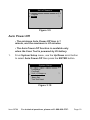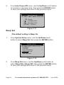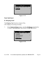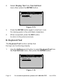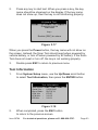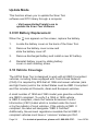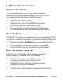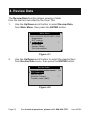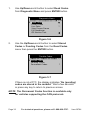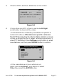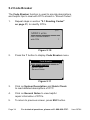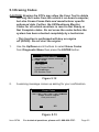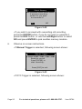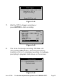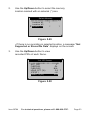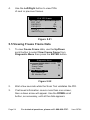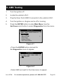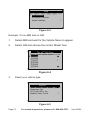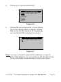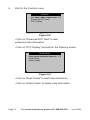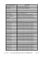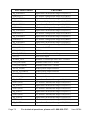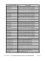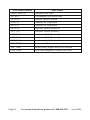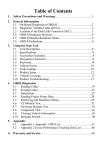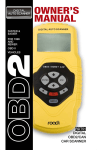
1
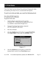
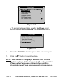
Owner’s Manual & Safety Instructions
Save This Manual Keep this manual for the safety warnings and precautions, assembly,
operating, inspection, maintenance and cleaning procedures. Write the product’s serial number in the
back of the manual near the assembly diagram (or month and year of purchase if product has no number).
Keep this manual and the receipt in a safe and dry place for future reference.
REV 15i
ITEM 60794
Visit our website at: http://www.harborfreight.com
Email our technical support at: [email protected]
When unpacking, make sure that the product is intact
and undamaged. If any parts are missing or broken,
please call 1-888-866-5797 as soon as possible.
Copyright© 2012 by Harbor Freight Tools®. All rights reserved.
No portion of this manual or any artwork contained herein may be reproduced in
any shape or form without the express written consent of Harbor Freight Tools.
Diagrams within this manual may not be drawn proportionally. Due to continuing
improvements, actual product may differ slightly from the product described herein.
Tools required for assembly and service may not be included.
Read this material before using this product.
Failure to do so can result in serious injury.
SAVE THIS MANUAL.
Table of Contents
1. Safety Precautions And Warnings........................ 3
2. General Information...............................................4
3. Using the Scan Tool..............................................10
4. Review Data...........................................................26
5. Diagnostics............................................................28
6. ABS Testing............................................................69
7. Print Data...............................................................73
8. Appendix................................................................75
9. Limited 90 Day Warranty.......................................84
Page 2
For technical questions, please call 1-888-866-5797.
Item 60794
1. Safety Precautions And Warnings
To prevent personal injury or damage to vehicles
and/ or the Scan Tool, read this instruction manual
first and observe the following safety precautions,
at a minimum, whenever working on a vehicle:
1.
Always perform automotive testing in a safe environment.
2.
Wear safety eye protection that meets ANSI standards.
3.
Keep clothing, hair, hands, tools, test equipment,
etc. away from all moving or hot engine parts.
4.
Operate the vehicle in a well-ventilated work area:
Exhaust gases are poisonous.
5.
Put blocks in front of the drive wheels and never
leave the vehicle unattended while running tests.
6.
Use extreme caution when working around the
ignition coil, distributor cap, ignition wires and
spark plugs. These components create hazardous
voltages when the engine is running.
7.
Put the transmission in PARK (for automatic
transmission) or NEUTRAL (for manual transmission)
and make sure the parking brake is engaged.
8.
Keep a fire extinguisher suitable for gasoline/
chemical/electrical fires nearby.
9.
Don't connect or disconnect any test equipment
while the ignition is on or the engine is running.
10.
Keep the Scan Tool dry, clean, free from oil, water or
grease. Use a mild detergent on a clean cloth to clean
the outside of the Scan Tool, when necessary.
Item 60794
For technical questions, please call 1-888-866-5797.
Page 3
2. General Information
2.1 On-Board Diagnostics (OBD) II
The first generation of On-Board Diagnostics (called OBD I)
was developed by the California Air Resources Board
(ARB) and implemented in 1988 to monitor some of the
emission control components on vehicles. As technology
evolved and the desire to improve the On-Board Diagnostic
system increased, a new generation of On-Board Diagnostic
system was developed. This second generation of OnBoard Diagnostic regulations is called OBD II.
The OBD II system is designed to monitor emission control systems
and key engine components by performing either continuous or
periodic tests of specific components and vehicle conditions. When
a problem is detected, the OBD II system turns on a warning lamp
(MIL) on the vehicle instrument panel to alert the driver typically
by the phrase of “Check Engine” or “Service Engine Soon”.
The system will also store important information about the
detected malfunction so that a technician can accurately
find and fix the problem. Here are three examples:
1.
Whether the Malfunction Indicator Light
(MIL) is commanded 'on' or 'off'
2.
Which, if any, DTCs are stored
3.
Readiness Monitor status
Page 4
For technical questions, please call 1-888-866-5797.
Item 60794
2.2 Diagnostic Trouble Codes (DTCs)
OBD II DTCs are codes that are stored by the vehicles' OnBoard Diagnostic system in response to a problem found
in the vehicle. These codes identify a particular problem
area and are intended to provide you with a guide as to
where a fault might be occurring within a vehicle.
OBD II DTCs consists of a five-digit alphanumeric code.
The first character, a letter, identifies which control system
sets the code. The other four characters, all numbers, provide
additional information on where the DTC originated and
the operating conditions that caused it to set. Here below
is an example to illustrate the structure of the digits:
DTC Example
P0202
Systems
B=Body
C=Chassis
P=Powertrain
U=Network
Code Type
Generic (SAE):
P0, P2, P34-P39
B0, B3
C0, C3
U0, U3.
Manufacturer Specific:
P1, P30-p33
B1, B2
C1, C2
U1, U2
Item 60794
Identifying specific
malfunctioning
section of the
systems
Sub-systems
1= Fuel and Air Metering
2= Fuel and Air Metering
3= Ignition System or Engine Misfire
4= Auxiliary Emission Controls
5= Vehicle Speed Control and Idle
Controls
6= Computer Output Circuits
7= Transmission Controls
8= Transmission Controls
For technical questions, please call 1-888-866-5797.
Page 5
2.3 Location of the Data Link Connector (DLC)
The DLC is the standardized 16-cavity connector where diagnostic
Scan Tools interface with the vehicle's on-board computer. The
DLC is usually located 12 inches from the center of the instrument
panel (dash), under or around the driver's side for most vehicles.
If the DLC is not located under dashboard, a label should be
there indicating its location. For some Asian and European
vehicles, the DLC is located behind the ashtray and the ashtray
must be removed to access the connector. If the DLC cannot be
found, refer to the vehicle’s Owner's Manual for the location.
2.4 OBD II Readiness Monitors
An important part of a vehicle's OBD II system are the Readiness
Monitors, which are indicators used to find out if all of the emissions
components have been evaluated by the OBD II system. They
are running periodic tests on specific systems and components
to ensure that they are performing within allowable limits.
Currently, there are eleven OBD II Readiness Monitors (or
I/M Monitors) defined by the U.S. Environmental Protection
Agency (EPA). Not all monitors are supported by all vehicles
and the exact number of monitors in any vehicle depends on
the motor vehicle manufacturer's emissions control strategy.
Page 6
For technical questions, please call 1-888-866-5797.
Item 60794
Continuous Monitors
Some of the vehicle components or systems are continuously
tested by the vehicle's OBD II system, while others are tested
only under specific vehicle operating conditions. The continuously
monitored components listed below are always ready:
1.
Misfire
2.
Fuel System
3.
Comprehensive Components (CCM)
Once the vehicle is running, the OBD II system is continuously
checking the above components, monitoring key engine sensors,
watching for engine misfire, and monitoring fuel demands.
Non-Continuous Monitors
Unlike the continuous monitors, many emissions and engine
system components require the vehicle to be operated
under specific conditions before the monitor is ready.
2.5 OBD II Monitor Readiness Status
OBD II systems must indicate whether or not the vehicle's PCM
monitor system has completed testing on each component.
Components that have been tested will be reported as “Ready”, or
“Complete”, meaning they have been tested by the OBD II system.
The purpose of recording readiness status is to allow
technicians to determine if the vehicle's OBD II system
has tested all the components and/or systems.
Item 60794
For technical questions, please call 1-888-866-5797.
Page 7
The Power-Train Control Module (PCM) sets a monitor to
“Ready” or “Complete” after an appropriate drive cycle has
been performed. The drive cycle that enables a monitor and
sets readiness codes to “Ready” varies for each individual
monitor. Once a monitor is set as “Ready” or “Complete”, it
will remain in this state. A number of factors, including erasing
of DTCs with a Scan Tool or a disconnected battery, can
result in Readiness Monitors being set to “Not Ready”.
Since the three continuous monitors are constantly evaluating, they
will be reported as “Ready” all of the time. If testing of a particular
supported non-continuous monitor has not been completed, the
monitor status will be reported as “Not Complete” or “Not Ready.”
In order for the OBD II monitor system to become ready,
the vehicle should be driven under a variety of normal
operating conditions. These operating conditions may
include a mix of highway driving and stop and go, city type
driving, and at least one overnight-off period. For specific
information on getting your vehicle's OBD II monitor system
ready, please consult your vehicle's Owner's Manual.
2.6 OBD II Definitions
Power-Train Control Module (PCM) -- The vehicle's onboard computer that controls engine and drive train.
Malfunction Indicator Light (MIL) -- Malfunction Indicator Light
(Service Engine Soon, Check Engine) is a term used for the light
on the instrument panel. It is to alert the driver and/or the repair
technician that there is a problem with one or more of vehicle's
systems and may cause emissions to exceed federal standards.
If the MIL illuminates with a steady light, it indicates that
a problem has been detected and the vehicle should be
serviced as soon as possible. Under certain conditions, the
MIL will blink or flash. This indicates a severe problem and
flashing is intended to discourage vehicle operation.
Page 8
For technical questions, please call 1-888-866-5797.
Item 60794
The vehicle's On-Board Diagnostic system cannot turn
the MIL off until necessary repairs are completed or
the condition no longer exists.
DTC -- Diagnostic Trouble Code that identifies which section
of the emission control system has malfunctioned.
OBD II Drive Cycle -- A specific mode of vehicle operation that
provides conditions required to set all the Readiness Monitors
applicable to the vehicle to the “Ready” condition. The purpose
of completing an OBD II drive cycle is to force the vehicle to run
its on-board diagnostics. Some form of a drive cycle needs to be
performed after DTCs have been erased from the PCM's memory
or after the battery has been disconnected. Running through a
vehicle's complete drive cycle will “set” the Readiness Monitors
so that future faults can be detected. Drive cycles vary depending
on the vehicle and the monitor that needs to be reset. For vehicle
specific drive cycle, consult the vehicle's Owner's Manual.
Freeze Frame Data -- When an emissions related fault occurs, the
OBD II system not only sets a code but also records a snapshot of
the vehicle operating parameters to help in identifying the problem.
This set of values is referred to as Freeze Frame Data and may
include important engine parameters such as engine RPM, vehicle
speed, air flow, engine load, fuel pressure, fuel trim value, engine
coolant temperature, ignition timing advance, or closed loop status.
Item 60794
For technical questions, please call 1-888-866-5797.
Page 9
3. Using the Scan Tool
3.1 Tool Description
10
1
11
2
6
4
3
8
5
7
9
1.
LCD Display – Displays menus and test results.
2.
ENTER BUTTON – Confirms a selection
(or action) from a menu. Starts recording live
data under Manual Trigger mode.
Page 10
For technical questions, please call 1-888-866-5797.
Item 60794
3.
ESC BUTTON – Cancels a selection (or action)
from a menu or returns to the previous menu.
4.
LEFT SCROLL BUTTON – When looking up DTC
definitions, moves to previous screens if DTC definition
covers more than one screen; deselects all marked
PID data when viewing or recording customized live
data list; moves to previous frames of data when
playing back live data. Updates DTC library.
5.
RIGHT SCROLL BUTTON – When looking up DTC
definitions, moves to next screens if DTC definition covers
more than one screen; selects/deselects PID data when
viewing or recording customized live data list; moves
to next frames of data when playing back live data.
6.
UP SCROLL BUTTON – Moves up through menu
and submenu items in menu mode. When more than one
screen of data is retrieved, moves up through the current
screen to the previous screens for additional data.
7.
DOWN SCROLL BUTTON – Moves down through
menu and submenu items in menu mode. When
more than one screen of data is retrieved, moves
down through the current screen to next screens for
additional data. It is also used for language setup.
8.
HELP BUTTON – Provides Help and
Code Breaker information.
9.
POWER SWITCH – Turns the Scan Tool
on/ off when powered by 9V battery; resets the
Scan Tool when powered by vehicle battery.
10.
OBD II CONNECTOR – Connects the
Scan Tool to the vehicle’s DLC.
11.
USB CONNECTOR – Connects the Scan Tool
to a computer for printing and upgrading.
Item 60794
For technical questions, please call 1-888-866-5797.
Page 11
3.2 Specifications
Display: Backlit, 128 x 64 pixel display with contrast adjustment
Operating Temperature: 0 to 60°C (32 to 140°F)
Storage Temperature: -20 to 70°C (-4 to 158°F)
External Power: 8.0 to 18.0 V power provided via vehicle battery
Internal Power: 9V battery
3.3 Accessories Included
1.
OBD II Cable – Provides power to tool and
communicates between tool and vehicle.
2.
USB Cable – Used to upgrade the Scan
Tool, and to print retrieved data.
3.
9V Battery – Supplies power to the Scan Tool
when disconnected from vehicle DLC.
4.
User's Manual – Instructions on tool operations.
5.
CD – Includes user's manual, update software, etc.
3.4 Navigation Characters
1.
► – Indicates current selection.
2.
– Indicates additional information is
available on next screen(s).
3.
– Indicates additional information is
available on previous screen(s).
4.
$ – Identifies the control module number
from which data is retrieved.
5.
? – Indicates Help or Code Breaker information is available.
6.
G – Indicates graphic viewing is available.
7.
Page 12
– Indicates battery level.
For technical questions, please call 1-888-866-5797.
Item 60794
3.5 Keyboard
No solvents such as alcohol are allowed to clean the Keyboard or
Display. Use a mild nonabrasive detergent and a soft cotton cloth.
Do not soak the Keyboard as the Keyboard is not waterproof.
3.6 Power
Internal Power
The Scan Tool has a 9V battery that provides
power for off-car reviewing and analysis. Press
the power key to turn on the Scan Tool.
Note: If the Scan Tool is stored for a long period of time, remove
the battery to prevent damage to the Scan Tool.
External Power
The Scan Tool is powered via the vehicle's DLC. Just
follow the steps below to turn on the Scan Tool:
1.
Connect the OBD II Cable to Scan Tool.
2.
Find the DLC on vehicle.
3.
Plug OBD II cable to the vehicle's DLC.
Item 60794
For technical questions, please call 1-888-866-5797.
Page 13
3.7 DTC Lookup
The DTC Lookup function is used to search for definitions of DTCs
stored in the DTC library and for Code Breaker information.
1.
From Main Menu, use the Up/Down scroll button to
select DTC Lookup then press the ENTER button.
Main Menu
Diagnostics
DTC Lookup
Review Data
Print Data
System Setup
Tool Information
2/6
?
Figure 3.1
• The numbers x/y in the upper right corner = where
x indicates the sequence of highlighted item and y
indicates total number of items under the menu.
• Press the ? button to view Help information of selected item.
2.
From DTC Lookup menu, use the Left/Right
button to move to the desired character, use the Up/
Down button to change selected digit/character,
then press the ENTER button to confirm.
DTC Lookup
P0001
[ ] – Left [ ] - Right
[ ][ ]- Change Digit
[ENTER]- Confirm
[ESC]- Exit
Figure 3.2
Page 14
For technical questions, please call 1-888-866-5797.
Item 60794
3.
View the DTC definition on screen. When the DTC definition
covers more than one screen, use the Left/Right button
to view additional information on previous/next screens.
• For manufacturer specific codes, you need
to select a vehicle make on an additional
screen to look for DTC definitions.
• If definition could not be found (SAE or Manufacturer
Specific), the Scan Tool displays “DTC definition not
found! Please refer to vehicle's User's Manual!”
• For Code Breaker information, press the ? button.
4.
To view previous or next DTC in the built- in
DTC library, use the Up/Down button.
5.
To enter another DTC, press the ESC
button to return to previous screen.
6.
To exit to Main Menu, press the ESC button.
3.8 System Setup
The Scan Tool allows you to make the following
adjustments and settings:
1.
Language: Selects the desired language.
2.
Contrast: Adjusts the contrast of the LCD display
3.
Unit of Measure: Sets the unit of measure to
English or Metric.
4.
Auto Power-Off: Sets automatic power-off limits.
5.
Beep Set: Turns on/off beep.
6.
Tool Self-test: Checks if the LCD display
and Keyboard are working normally.
Item 60794
For technical questions, please call 1-888-866-5797.
Page 15
7.
Tool Information: Allows viewing of some
important information such as serial number and
software version number of the Scan Tool.
8.
Update Mode: Used for updating the Scan Tool.
• Settings of the unit will remain until change
to the existing settings are made.
To Enter the System Setup Menu
From the Main Menu, use the Up/Down scroll button to
select System Setup, then press the ENTER button.
............ ..Main Menu…… ……………
5/6
Diagnostics
DTC Lookup
Review Data
?
Print Data
System Setup
Tool Information
Language
Figure 3.3
•English is the default language.
1.
From System Setup menu, use the Up/Down scroll button
to select Language, then press the ENTER button.
System Setup
Language
Contrast
Unit of Measure
Auto Power-off
Beep Set
Tool Self-test
1/6
?
Figure 3.4
Page 16
For technical questions, please call 1-888-866-5797.
Item 60794
2.
Use the Up/Down scroll button to select the desired
language, then press the ENTER button to save
your selection and return to previous screen.
Language
1/3
English
Français
Español
Contrast
1.
Figure 3.5
From System Setup menu, use the Up/Down scroll button
to select Contrast, then press the ENTER button.
System Setup
Language
Contrast
Unit of Measure
Auto Power-Off
Beep Set
Tool Self-test
2/6
?
Figure 3.6
Item 60794
For technical questions, please call 1-888-866-5797.
Page 17
2.
From Contrast menu, use the Up/Down scroll button to
increase or decrease contrast, then press the ENTER button
to save your settings and return to the previous menu.
Contrast
(30%)
Use
Unit of Measure
or
to change
Figure 3.7
• Metric is the default measurement unit.
1.
From System Setup menu, use the Up/Down scroll button
to select Unit of Measure, then press the ENTER button.
System Setup
Language
Contrast
Unit of Measure
Auto Power-off
Beep Set
Tool Self-test
3/6
?
Figure 3.8
2.
From Unit of Measure menu, use the Up/ Down scroll
button to select the desired unit of measurement,
then press the ENTER button to save your
settings and return to the previous menu..
Page 18
For technical questions, please call 1-888-866-5797.
Item 60794
…………….Unit of Measure…… … ….
2/2
English
Metric
?
Figure 3.9
Auto Power-Off
• The minimum Auto Power-Off time is 1
minute, and the maximum is 20 minutes.
• The Auto Power-Off function is available only
when the Scan Tool is powered by 9V battery.
1.
From System Setup menu, use the Up/Down scroll button
to select Auto Power-Off then press the ENTER button.
System Setup
Language
Contrast
Unit of Measure
Auto Power-off
Beep Set
Tool Self-test
4/6
?
Figure 3.10
Item 60794
For technical questions, please call 1-888-866-5797.
Page 19
2.
From Auto Power-Off menu, use the Up/Down scroll button
to increase or decrease time, then press the ENTER button
to save your settings and return to the previous menu.
Auto Power-off
01 Minute
[ ] – Increase time
[ ] – Decrease time
[ENTER] - Confirm
Beep Set
Figure 3.11
•The default setting is Beep On.
1.
From System Setup menu, use the Up/Down scroll
button to select Beep Set then press the ENTER button.
System Setup
Language
Contrast
Unit of Measure
Auto Power-off
Beep Set
Tool Self-test
5/6
?
Figure 3.12
2.
From Beep Set menu, use the Up/Down scroll button to
select Beep ON or Beep OFF, then press the ENTER button
to save your settings and return to the previous menu.
Page 20
For technical questions, please call 1-888-866-5797.
Item 60794
Beep Set
2/2
Beep ON
Beep OFF
?
Figure 3.13
Tool Self-test
A. Display test
The Display Test function checks if the
LCD display is working normally.
1.
From System Setup menu, use the Up/Down scroll button
to select Tool Self-test, then press the ENTER button.
System Setup
Language
Contrast
Unit of Measure
Auto Power-off
Beep Set
Tool Self-test
6/6
?
Figure 3.14
Item 60794
For technical questions, please call 1-888-866-5797.
Page 21
2.
Select Display Test from Tool Self-test
menu then press the ENTER button.
Tool Self-test
Display Test
Keyboard Test
1/2
?
Figure 3.15
3.
Press the ENTER button again to start test. Look
for missing spots in the solid black characters.
4.
When completed, press the ESC button
to return to the previous screen.
B. Keyboard Test
The Keyboard Test function verifies that
the keys are functioning properly.
1.
Use the Up/Down scroll button to select Keyboard Test from
the Tool Self-test menu, then press the ENTER button.
Tool Self-test
Display Test
Keyboard Test
2/2
?
Figure 3.16
Page 22
For technical questions, please call 1-888-866-5797.
Item 60794
2.
Press any key to start test. When you press a key, the key
name should be observed on the display. If the key name
does not show up, then the key is not functioning properly.
Keyboard Test
Press any key to
start test
key:
Double [ESC] to return
Figure 3.17
When you press the Power button, the key name will not show on
the screen. Instead, the Scan Tool should reset when powered by
vehicle battery, or turn off when powered by 9V battery. If the Scan
Tool does not reset or turn off, the key is not working properly.
3.
Double press ESC to return to previous menu.
Tool Information
1.
From System Setup menu, use the Up/Down scroll button
to select Tool Information, then press the ENTER button.
Tool Information
Serial No. :
Burn Date:
S/W Ver :
H/W Ver :
LIB Ver :
00000006
05/03/11
V3.00
V1.02
V1.01
Figure 3.18
2.
When completed, press the ESC button
to return to the previous screen.
Item 60794
For technical questions, please call 1-888-866-5797.
Page 23
Update Mode
This function allows you to update the Scan Tool
software and DTC library through a computer.
• Visit www.HarborFreight.com to
update the Scan Tool software.
3.9 9V Battery Replacement
When the
icon appears on the screen, replace the battery.
1.
Locate the battery cover on the back of the Scan Tool.
2.
Remove the battery cover screw and
slide the battery cover off.
3.
Remove discharged battery and install a new 9V battery.
4.
Reinstall battery cover by sliding battery
cover on and installing screw.
3.10 Vehicle Coverage
The 60794 Scan Tool is designed to work with all OBD II compliant
vehicles, including those equipped with Control Area Network
(CAN). It is required by EPA that all 1996 and newer vehicles (cars
and light trucks) sold in the United States must be OBD II compliant
and this includes all Domestic, Asian and European vehicles.
A small number of 1994 and 1995 model year gasoline vehicles
are OBD II compliant. To verify if a 1994 or 1995 vehicle
is OBD II compliant, check the Vehicle Emissions Control
Information (VECI) Label which is located under the hood
or by the radiator of most vehicles. If the vehicle is OBD II
compliant, the label will designate “OBD II Certified”.
Additionally, Government regulations mandate that all OBD II
compliant vehicles must have a “common” sixteen-pin DLC.
Page 24
For technical questions, please call 1-888-866-5797.
Item 60794
3.11 Product Troubleshooting
Vehicle Linking Error
A communication error occurs if the Scan Tool fails to
communicate with the vehicle's Engine Control Unit (ECU).
You need to do the following to identify the error:
1.
Verify that the ignition is ON.
2.
Verify that the Scan Tool's OBD II connector is
securely connected to the vehicle's DLC.
3.
Turn the ignition off and wait for about 10 seconds.
Turn the ignition back to on and continue the testing.
Operating Error
If the Scan Tool freezes, an exception occurs, or the vehicle's ECU
is too slow to respond to requests, you need to reset the Scan Tool:
1.
Press and hold the POWER button for at least 2 seconds.
2.
Turn the ignition off and wait for about 10 seconds.
Turn the ignition back to on and continue the testing.
Scan Tool doesn’t power up
If the Scan Tool won't power up or operates incorrectly
in any other way, you need to do the following:
1.
Verify that the Scan Tool's OBD II connector is
securely connected to the vehicle's DLC.
2.
Verify that the DLC pins are not bent or broken.
Clean the DLC pins if necessary.
3.
Verify that the vehicle battery measures at least 8 volts.
Item 60794
For technical questions, please call 1-888-866-5797.
Page 25
4. Review Data
The Review Data function allows viewing of data
from the last test recorded by the Scan Tool.
1.
Use the Up/Down scroll button to select Review Data
from Main Menu, then press the ENTER button.
Main Menu
3/6
Diagnostics
DTC Lookup
Review Data
Print Data
System Setup
Tool Information
?
Figure 4.1
2.
Use the Up/Down scroll button to select the desired item
from Review Data menu, then press the ENTER button.
Review Data
1/4
I/M Readiness
Vehicle Info.
Modules Present
Trouble codes (ABS)
?
Figure 4.2
Page 26
For technical questions, please call 1-888-866-5797.
Item 60794
• If no data from a previously tested vehicle is
recorded, only Modules Present data containing
module ID and protocol type can be reviewed.
Review Data
1/1
Modules Present
?
Figure 4.3
• Diagnostics results can be reviewed from this list
only when any DTC is detected in previous tests.
3.
Review selected data on screen.
1/1
C1201
Engine Control
System Malfunction
?
Figure 4.4
NOTE: Data stored in a language different from current
system settings of the Scan Tool will not be reviewable.
Please adjust the language settings accordingly. A
reminder will pop up under such circumstances.
Item 60794
For technical questions, please call 1-888-866-5797.
Page 27
5. Diagnostics
When more than one vehicle control module is detected by the
Scan Tool, you will be prompted to select the module where the data
may be retrieved. The most often to be selected are the Powertrain
Control Module (PCM) and Transmission Control Module (TCM).
CAUTION: Don’t connect or disconnect any test
equipment with ignition on or engine running.
1.
Turn the ignition off.
2.
Locate the vehicle's DLC.
3.
Plug the Scan Tool's OBD II connector into the vehicle's DLC.
4.
Turn the ignition on. Engine can be off or running.
5.
Turn on the Scan Tool by pressing the Power
button. Use the Up/Down scroll button to select
Diagnostics from the Main Menu.
Main Menu
1/6
Diagnostics
DTC Lookup
Review Data
Print Data
System Setup
Tool Information
?
Figure 5.1
Page 28
For technical questions, please call 1-888-866-5797.
Item 60794
6.
Press the ENTER button to wait for the Menu to appear.
Diagnostics
1/2
OBD2/EOBD
ABS
?
Figure 5.2
7.
Select OBD2/EOBD and wait for a few seconds; a sequence
of messages displaying the OBD II protocols will be observed
on the display until the vehicle protocol is detected.
• If the Scan Tool fails to communicate with the
vehicle’s ECU more than three times, a “LINKING
ERROR!” message shows up on the display.
a. Verify that the ignition is ON
b. Check if the Scan Tool's OBD II connector is
securely connected to the vehicle's DLC
c. Verify that the vehicle is OBD II compliant
d. Turn the ignition off and wait for about 10 seconds. Turn the
ignition back to on and repeat the procedure from step 5.
• If the “LINKING ERROR!” message does not go away,
have the tool inspected by a qualified technician.
Item 60794
For technical questions, please call 1-888-866-5797.
Page 29
8.
You will be prompted to erase previously stored data.
• Review previously stored data
thoroughly before erasing.
Diagnostic
Erase previously
stored data to save
data from this test?
YES
NO
If you wish to erase the data, press the ENTER button
Figure 5.3
9.
If you wish to erase the data, press the ENTER button; if
you do not want to erase the data, press ESC to exit or use
Left/ Right button to select NO and press ENTER to continue.
10.
View a summary of the System Status. Wait a few seconds
or press any key for Diagnostic Menu to come up.
System Status
MIL Status
Codes Found
Monitors N/A
Monitors OK
Monitors INC
ON
6
3
3
5
Figure 5.4
Page 30
For technical questions, please call 1-888-866-5797.
Item 60794
• If more than one module is detected, you will be
prompted to select a module before testing.
Control Module
Engine
Module $A4
1/2
?
Figure 5.5
• Use the Up/Down scroll button to select a
module then press the ENTER button.
5.1 Reading Codes
• Reading Codes can be done with the key on engine off
(KOEO) or with the key on engine running (KOER).
• Stored Codes are also known as “hard codes” or
"permanent codes", These codes will cause
the control module to illuminate the (MIL)
when an emission-related fault occurs.
• Pending Codes are also referred to as “maturing codes” or
“continuous monitor codes”. They indicate problems that the
control module has detected during the current or last driving
cycle but are not considered serious yet. Pending Codes will
not turn on the MIL. If the fault does not occur within a certain
number of warm-up cycles, the DTC clears from memory.
• Permanent Codes are DTCs that are "confirmed" and
are retained in the non-volatile memory of the vehicle's
on-board computer until the appropriate monitor for
each DTC has determined that the malfunction is no
longer present and is not commanding the MIL on.
Item 60794
For technical questions, please call 1-888-866-5797.
Page 31
1.
Use Up/Down scroll button to select Read Codes
from Diagnostic Menu and press ENTER button.
Diagnostic Menu
Read Codes
Erase Codes
Live Data
View Freeze Frame
I/M Readiness
O2 Monitor Test
1/11
?
Figure 5.6
2.
Use the Up/Down scroll button to select Stored
Codes or Pending Codes from the Read Codes
menu then press the ENTER button.
Trouble Codes
Stored Codes
Pending Codes
Permanent Codes
1/3
?
Figure 5.7
If there is not a DTC, the display indicates “No (pending)
codes are stored in the module!” Wait a few seconds
or press any key to return to previous screen.
NOTE: The Permanent Codes function is available only
for vehicles supporting the CAN protocols.
Page 32
For technical questions, please call 1-888-866-5797.
Item 60794
3.
View the DTCs and their definitions on the screen.
P1633
1/1
$10
BUICK
Ignition 0 Switch Circuit
?
Figure 5.8
4.
If more than one DTC is found, use the Left/ Right
scroll button to check all the codes.
• If retrieved DTCs contain any manufacturer specific or
enhanced codes, a “Manufacturer specific codes are
found! Press any key to select vehicle make!” message
comes up prompting you to select vehicle manufacturer to
view DTC definitions. Use Up/Down scroll button to select
manufacturer and then press ENTER button to confirm.
Vehicle Manufacturer
BUICK
BMW
CADILLAC
CHEVROLET
CHRYSLER
FORD
1/28
?
Figure 5.9
• If the manufacturer of your vehicle is not
listed, use the Up/Down scroll button to select
Other then press the ENTER button.
Item 60794
For technical questions, please call 1-888-866-5797.
Page 33
5.2 Code Breaker
The Code Breaker function is used to provide descriptions
and helpful tips to deal with DTCs stored in “Stored Codes”.
1.
Repeat steps in section "5.1 Reading Codes"
on page 31, to identify DTCs.
1/11
U0101
$07E8
Lost Communication
with TCM
?
Figure 5.10
2.
Press the ? button to display Code Breaker menu.
Code Breaker
System Description
Quick Check
General Notes
1/3
Figure 5.11
3.
Click on System Description and Quick Check
to read detailed descriptions of DTC.
4.
Click on General Notes to view helpful
repair information of DTCs.
5.
To return to previous screen, press ESC button.
Page 34
For technical questions, please call 1-888-866-5797.
Item 60794
5.3 Erasing Codes
CAUTION: Erasing the DTCs may allow the Scan Tool to delete
not only the codes from the vehicle’s on-board computer,
but also Freeze Frame Data and manufacturer specific
enhanced data. Further, the I/M Readiness Monitor
Status for all vehicle monitors is reset to Not Ready or
Not Complete status. Do not erase the codes before the
system has been checked completely by a technician.
• This function is performed with key on engine
off (KOEO). Do not start the engine.
1.
Use the Up/Down scroll buttons to select Erase Codes
from Diagnostic Menu then press the ENTER button.
Diagnostic Menu
Read Codes
Erase Codes
Live Data
View Freeze Frame
I/M Readiness
O2 Monitor Test
2/11
?
Figure 5.12
2.
A warning message comes up asking for your confirmation.
Erase Codes
Erase trouble codes!
Are you sure?
YES
NO
Figure 5.13
Item 60794
For technical questions, please call 1-888-866-5797.
Page 35
• If you do not want to proceed with erasing codes, press ESC
button or use Left/Right scroll button to select NO to exit. A
message of “Command Cancelled!” will appear. Wait a few
seconds or press any key to return to Diagnostic Menu.
3.
Press the ENTER button to confirm.
• If the codes are cleared successfully, an “Erase
Done!” confirmation message shows on the display.
Erase Codes
Erase Done!
Press any key to con.
Figure 5.14
• If the codes are not cleared, then an “Erase Failure.
Turn Key on with Engine off!” message appears
Erase Codes
Erase Failure.
Turn Key on with
Engine Off!
Press any key to con.
Figure 5.15
Clearing the error code will not repair the car.
Repair the car, then clear the error code.
4.
Press any button to return to Diagnostic Menu.
Page 36
For technical questions, please call 1-888-866-5797.
Item 60794
5.4 Viewing Data
Viewing Live Data
1.
To view Live Data, use the Up/Down scroll
button to select Live Data from the Diagnostic
Menu then press the ENTER button.
Diagnostic Menu
Read Codes
Erase Codes
Live Data
View Freeze Frame
I/M Readiness
O2 Monitor Test
3/11
?
Figure 5.16
2.
Wait a few seconds while the Scan Tool validates the PID.
Live Data
Reading PID.01
- Please Wait -
Figure 5.17
Item 60794
For technical questions, please call 1-888-866-5797.
Page 37
3.
Use the Up/Down scroll button to select View Data
from Live Data menu then press the ENTER button.
……………… .Live Data………… ……..
1/3
View Data
Record Data
?
Playback Data
Figure 5.18
Viewing Complete Data Set
1.
To view a complete set of data, use Up/Down scroll
button to select Complete Data Set from View
Data menu then press the ENTER button.
…………………View Data…… ……… …..
1/3
Complete Data Set
Custom Data Set
Unit of Measure
?
Figure 5.19
Page 38
For technical questions, please call 1-888-866-5797.
Item 60794
2.
View live PIDs on the screen. Use the Up/Down scroll button
for more PIDs if an or arrow appears on the screen. .
Live Data……
DTC_CNT
FUELSYS1
FUELSYS2
LOAD_PCT (%)
ETC( )
SHRTFT1 (%)
……. …
6
0
0L
-- ?
0.0
-40
99.2
Figure 5.20
• The number x to the top right of the screen
indicates sequence of the highlighted item.
• To view full name of the highlighted PID, press the ? button.
• If the G icon appears when a PID is highlighted, graphic
information is available. Press ENTER to view graph.
RPM (/min)
975
1725
925
Figure 5.21
3.
Press the ESC button to return to previous menu.
Item 60794
For technical questions, please call 1-888-866-5797.
Page 39
Viewing Custom Data Set
1.
To view customized PID data, use the Up/Down
scroll button to select Custom Data Set from View
Data menu then press the ENTER button.
……………….View Data……………… ….
Complete Data Set
Custom Data Set
Unit of Measure
2/3
?
Figure 5.22
2.
Observe on-screen instructions.
……………Custom Data Set……… …..
[ ] – Select/Deselect
[ ] – Deselect all
[ENTER] – Confirm
[ESC] - Cancel
Figure 5.23
3.
Use the Right button to deselect/select data parameters,
and use the Up/Down scroll button to move up and down.
Selected parameters are marked with solid squares.
…………..Custom Data Set………… …
4/25
*DTC_CNT
#01
FUELSYS1
*FUELSYS2
#02
?
*LOAD_PCT
#03
ETC( )
SHRTFT1
Page 40
Figure 5.24
For technical questions, please call 1-888-866-5797.
Item 60794
• The numbers x/y in the upper right corner = where x
indicates sequence of highlighted item and y indicates the
order that the parameters are selected and will be displayed.
• If you want to deselect all marked items or select
all items, press the LEFT button. A message
comes up to ask for your confirmation.
………………Deselect All………………….
Deselect all
selected PID’s?
YES
NO
Figure 5.25
• If you decide to deselect these items, press ENTER;
if you decide not to, press ESC or use the Up/Down
scroll button to select NO to continue PID selections.
4.
Press the ENTER button to view selected PIDs on screen.
………………….Live Data………………….
4
DTC_CNT
0
FUELSYS2
0L
ETC( )
-40
?
SHRTFT1 (%)
99.2
Figure 5.26
5.
Use the ESC button to return to previous menu.
Item 60794
For technical questions, please call 1-888-866-5797.
Page 41
Recording Data
The Record Data function allows recording vehicle
modules’ PIDs to help diagnose intermittent vehicle
problems. A recording includes 5 frames of live data before
trigger event and several frames after trigger event.
There are two trigger modes used to record data:
1.
Manual Trigger - allows user to press the
ENTER button to start recording.
2.
DTC Trigger - automatically records PID data when a
fault that causes a DTC to set is detected by vehicle.
CAUTION: DO NOT try to drive and operate the Scan
Tool at the same time! Always have another
person operate the Scan Tool while driving.
1.
To record live data, use the Up/Down scroll
button to select Record Data from Live Data
menu then press the ENTER button.
……………….Live Data…………………….
2/3
View Data
Record Data
Playback Data
?
Figure 5.27
Page 42
For technical questions, please call 1-888-866-5797.
Item 60794
Recording Complete Data Set
1.
To record a complete set of live data, use the Up/ Down
scroll button to select Complete Data Set from
Record Data menu then press the ENTER button.
………………..Record Data……… ……..
1/3
Complete Data Set
Custom Data Set
Unit of Measure
?
Figure 5.28
2.
Use the Up/Down scroll button to select a trigger
mode then press the ENTER button.
…….……Pick Trigger Mode……… ……
1/2
Manual Trigger
DTC Trigger
?
Figure 5.29
• If data from previously tested vehicle is not erased, data
from current test will be stored in a temporary cache.
Item 60794
For technical questions, please call 1-888-866-5797.
Page 43
3.
Use the Up/Down scroll button to select a memory
location then press the ENTER button.
…………….Select Memory………… …..
1/3
Location #1
*
Location #2
Location #3
?
Figure 5.30
• The asterisk (*) icon on the screen indicates that there
is a previous recording in the memory location.
• If you select a location marked with an asterisk (*) icon, a
message prompting to overwrite old recording displays.
Select Memory
...
A previous recording
exists! Do you want
to overwrite it?
YES
NO
Figure 5.31
• If you wish to proceed with overwriting the old recording,
press the ENTER button; if you do not wish to overwrite
it, use the Left/Right button to select NO or press
the ESC button to pick another memory location.
Page 44
For technical questions, please call 1-888-866-5797.
Item 60794
4.
Observe on-screen instructions.
• If Manual Trigger is selected, the following screen shows:
……………Manual Trigger……………...
Ready to record!
Press [ENTER] to
start recording…
Press [ESC] to exit
Figure 5.32
• If DTC Trigger is selected, following screen shows:
………………….DTC Trigger……………..
Waiting for DTC to
trigger recording…
Press [ESC] to exit
Figure 5.33
5.
Wait for DTC to trigger recording or
press ENTER to start recording.
Note: Drive until a DTC is detected when DTC
Trigger is selected. If no DTCs are detected,
press ESC to exit recording.
Item 60794
For technical questions, please call 1-888-866-5797.
Page 45
Recording…
DTC_CNT
FUELSYS1
FUELSYS2
LOAD_PCT(%)
ETC( )
SHRTFT1(%)
0
0L
-0.0
-40
99.2
5/46
6
?
Figure 5.34
•The numbers x/y in the upper right corner =
where x indicates the number of recorded frames and
y indicates the maximum frames that can be recorded.
6.
The Scan Tool keeps recording PID data until
user presses the ESC button, selected memory
location is full, or it completes recording. A message
prompting to playback data shows on the screen.
Record Data
Record Done!
Playback data?
YES
NO
Figure 5.35
• If you wish to playback recorded data, press the ENTER
button; if you do not wish to playback, press the ESC
button, or use Left/Right button to select NO then press
the ENTER button to return to Record Data menu.
Page 46
For technical questions, please call 1-888-866-5797.
Item 60794
Recording Custom Data Set
1.
To record customized data, use the Up/Down scroll
button to select Custom Data Set from Record
Data menu then press the ENTER button.
………………Record Data…………… …
2/3
Complete Data Set
Custom Data Set
Unit of Measure
?
Figure 5.36
2.
Observe on-screen instructions. Press the ENTER
button to continue; press the ESC button, or use
Left/Right button to select NO then press the
ENTER button to return to Record Data menu.
……… …Custom Data Set………
…
[ ] – Select/deselect
[ ] – Deselect all
[ENTER] – Confirm
[ESC] – Cancel
YES
NO
Figure 5.37
Item 60794
For technical questions, please call 1-888-866-5797.
Page 47
3.
Use the RIGHT button select/deselect data
parameters. Selected parameters are marked with
solid squares. Press the ENTER button to confirm.
…………Custom Data Set……… ……..
6/25
*DTC_CNT
#01
FUELSYS1
*FUELSYS2
#02
?
*LOAD_PCT
#03
ETC
SHRTFT1
Figure 5.38
• If you wish to deselect all marked items, press LEFT button.
• A message comes up to ask for your confirmation.
……
….Deselect All…………………..
Deselect all
selected PIDs?
YES
NO
Figure 5.39
• If you decide to deselect these items, press
ENTER; if you decide not to, press the ESC button,
or use the Up/Down button to select NO and
press ENTER to continue PID selections.
4.
Use the Up/Down scroll button to select a Trigger
Mode then press the ENTER button.
Page 48
For technical questions, please call 1-888-866-5797.
Item 60794
……………Pick Trigger Mode…… …….
1/2
Manual Trigger
DTC Trigger
?
Figure 5.40
• If data from a previously tested vehicle is not erased,
data from current test will be stored in temporary cache.
5.
Use the Up/Down scroll button to select a Memory
Location then press the ENTER button.
…………. Select Memory……… ……….
1/3
Location #1
*
Location #2
Location #3
?
Figure 5.41
•The asterisk (*) icon on the screen indicates that there
is a previous recording in the memory location.
• If you select a location marked with an asterisk (*) icon, a
message prompting to overwrite old recording is displayed.
Item 60794
For technical questions, please call 1-888-866-5797.
Page 49
…………….Select Memory…………… ..
A previous recording
exists! Do you want
to overwrite it?
YES
NO
Figure 5.42
• If you wish to proceed with overwriting old recording,
press the ENTER button; if you do not wish to overwrite it,
press the ESC button, or use the Left/Right button to select
NO and press ENTER to pick another memory location.
6.
Observe on-screen instructions.
• If Manual Trigger is selected, following screen shows:
………………Manual Trigger…………….
Ready to record!
Press [ENTER] to
start recording…
Press [ESC] to exit
Figure 5.43
• If DTC Trigger is selected, following screen shows:
Page 50
For technical questions, please call 1-888-866-5797.
Item 60794
…………
DTC Trigger……
……
Waiting for DTC to
trigger recording…
Press [ESC] to exit
Figure 5.44
7.
Wait for DTC to trigger recording or
press ENTER to start recording.
Recording…
32/283
DTC_CNT
FUELSYS1
FUELSYS2
LOAD_PCT(%)
ETC( )
SHRTFT1(%)
0
0L
-0.0
-40
99.2
6
?
Figure 5.45
8.
The Scan Tool keeps recording PID data until
user presses ESC button, the selected memory
location is full, or it completes recording. A message
prompting to playback data shows on the screen.
………………..Record Data………………
Record Done!
Playback data?
YES
NO
Figure 5.46
Item 60794
For technical questions, please call 1-888-866-5797.
Page 51
• If you wish to playback recorded data, press the
ENTER button; if you do not wish to playback, press the
ESC button, or use the Left/Right button to select NO then
press the ENTER button to return to Record Data menu.
………………Record Data…………………
1/3
Complete Data Set
Custom Data Set
Unit of Measure
?
Figure 5.47
Playback Data
The Playback Data function allows viewing
of previously stored PID data.
1.
To playback recorded data, use the Up/Down
scroll button to select Playback Data from Live
Data menu then press the ENTER button.
…………….… Live Data………… ……….
3/3
View Data
Record Data
Playback Data
?
Figure 5.48
• You are also allowed to playback recorded
data immediately after recording.
Page 52
For technical questions, please call 1-888-866-5797.
Item 60794
2.
Use the Up/Down button to select the memory
location marked with an asterisk (*) icon.
Select Memory
Location #1
Location #2
Location #3
*
*
3/3
?
Figure 5.49
• If there is no recording in selected location, a message “Not
Supported or Stored No Data” displays on the screen.
3.
Use the Up/Down button to view
recorded PIDs of each frame.
1 of 135 frame
DTC_CNT
FUELSYS1
FUELSYS2
LOAD_PCT (%)
ETC( )
SHRTFT1(%)
…
6
0
OL
N/A
0.0 ?
-40
99.2
Figure 5.50
Item 60794
For technical questions, please call 1-888-866-5797.
Page 53
4.
Use the Left/Right button to view PIDs
of next or previous frames.
6 of 135 frame
DTC_CNT
FUELSYS1
FUELSYS2
LOAD_PCT(%)
ETC( )
SHRTFT1(%)
0
OL
N/A
0.0
-40
99.2
4
?
Figure 5.51
5.5 Viewing Freeze Frame Data
1.
To view Freeze Frame data, use the Up/Down
scroll button to select View Freeze Frame from
Diagnostic Menu then press the ENTER button.
...... ...Diagnostic Menu..... ........
4/11
Read Codes
Erase Codes
Live Data
?
View Freeze Frame
I/M Readiness
O2 Monitor Test
Figure 5.52
2.
Wait a few seconds while the Scan Tool validates the PID.
3.
If retrieved information covers more than one screen,
then a down arrow will appear. Use the DOWN scroll
button, as necessary, until all the data appears.
Page 54
For technical questions, please call 1-888-866-5797.
Item 60794
…………View Freeze Frame… ……….
DTCFRZF
FUELSYS1
FUELSYS2
LOAD_PCT (%)
ECT( )
SHRTFT1 (%)
P1633
OL
-0.0 ?
-40
99.2
2
Figure 5.53
• If there is no freeze frame data available,
an advisory message “No freeze frame
data stored!” shows on the display.
4.
If you want to view full name of a PID, use the Up/Down
scroll button to select the PID, then press the HELP button.
……………… ..FUELSYS1………
…….
Fuel System 1 Status
Figure 5.54
5.
Press ESC button to return to previous screen.
Item 60794
For technical questions, please call 1-888-866-5797.
Page 55
5.6 Retrieving I/M Readiness Status
The I/M Readiness Status function is used to check the
operations of the Emission System on OBD II compliant vehicles.
It is an excellent function to use prior to having a vehicle
inspected for compliance to a state Emissions Program.
Some of the latest vehicle models may support
two types of I/M Readiness tests:
• Since DTCs Cleared - indicates status of the
monitors since the DTCs are erased.
• This Drive Cycle - indicates status of monitors
since the beginning of the current drive cycle.
An I/M Readiness Status result of “NO” does not necessarily
indicate that the vehicle being tested will fail the state I/M
inspection. For some states, one or more such monitors may
be allowed to be “Not Ready” to pass the Emissions Test.
1.
Use the Up/Down scroll button to select I/M Readiness
from Diagnostic Menu and press ENTER button.
...........Diagnostic Menu....... .....
5/11
Read Codes
Erase Codes
Live Data
?
View Freeze Frame
I/M Readiness
O2 Monitor Test
Figure 5.55
2.
Wait a few seconds while the Scan Tool validates the PID.
Page 56
For technical questions, please call 1-888-866-5797.
Item 60794
3.
If the vehicle supports both types of tests, then both
types will be shown on the screen for selection.
……………I/M Readiness………… ….
1/2
Since DTCs Cleared
This Drive Cycle
?
Figure 5.56
4.
Use the Up/Down scroll button, as necessary,
to view the status of the MIL light (“ON” or
“OFF) and the following monitors:
• Misfire Monitor -- Misfire monitor
• Fuel System Mon -- Fuel System Monitor
• Comp. Component -- Comprehensive Component Monitor
• Catalyst Mon -- Catalyst Monitor
• Htd Catalyst -- Heated Catalyst Monitor
• EVAP System Mon -- Evaporative System Monitor
• Sec Air System -- Secondary Air Monitor
• A/C Refrig Mon -- A/C system Monitor
• Oxygen Sens Mon -- O2 Sensors Monitor
• Oxygen Sens Htr --O2 Sensor Heater Monitor
• EGR System Mon -- EGR System Monitor
Item 60794
For technical questions, please call 1-888-866-5797.
Page 57
System Mon -- EGR System Monitor
…………Since DTCs Cleared… ………
1
MIL Status
OFF
Misfire Monitor
OK
Fuel System Mon
OK ?
Comp. Component
OK
Catalyst Mon
INC
Htd Catalyst
N/A
Figure 5.57
5.
If the vehicle supports readiness test of “This Drive
Cycle”, a screen of the following displays:
…………..This Drive Cycle……… …….
1
MIL Status
OFF
Misfire Monitor
OK
Fuel System Mon
N/A
?
Comp. Component
OK
Catalyst Mon
INC
Htd Catalyst
N/A
Figure 5.58
5.7 O2 Monitor Test
OBD II regulations set by SAE require that relevant vehicles
monitor and test the oxygen (O2) sensors to identify problems
related to fuel efficiency and vehicle emissions. These tests
are not on-demand tests and they are done automatically when
engine operating conditions are within specified limits. These test
results are saved in the vehicle's on-board computer's memory.
The O2 Monitor Test function allows retrieval and viewing
of O2 sensor monitor test results for the most recently
performed tests from the vehicle's on-board computer.
Page 58
For technical questions, please call 1-888-866-5797.
Item 60794
The O2 Monitor Test function is not supported by vehicles
which communicate using a controller area network
(CAN). For O2 Monitor Test results of CAN-equipped
vehicles, see "5.8 On-Board Monitor Test" on page 61.
1.
Use the Up/Down scroll button to select O2 Monitor
Test from Diagnostic Menu and press ENTER button.
;........Diagnostic Menu............. .
6/11
Read Codes
Erase Codes
Live Data
?
View Freeze Frame
I/M Readiness
O2 Monitor Test
Figure 5.59
2.
Wait a few seconds while the Scan Tool validates the PID.
3.
Use the Up/Down scroll button to select an O2 sensor
from O2 Monitor Test menu and press ENTER button.
............O2 Monitor Test……… … …
2/8
O2 Bank1 Sensor1
O2 Bank1 Sensor2
O2 Bank1 Sensor3
?
O2 Bank1 Sensor4
O2 Bank2 Sensor1
O2 Bank2 Sensor2
Figure 5.60
Item 60794
For technical questions, please call 1-888-866-5797.
Page 59
…………….O2 Monitor Test…………..
The selected mode is
not supported!
Press any key to con.
Figure 5.61
4.
View test results of selected O2 sensor.
… ……….O2 Bank1 Sensor2………….
1/31
Rich-Lean Threshd V
Lean-Rich Threshd V
Low for Switch (V)
?
High for Switch (V)
Rich-Lean Threshd S
Lean-Rich Threshd S
Figure 5.62
5.
Use the Up/Down scroll button to view more
screens of data if an or icon displays.
6.
Press the ESC button to return to the previous menu.
Page 60
For technical questions, please call 1-888-866-5797.
Item 60794
5.8 On-Board Monitor Test
The On-Board Monitor Test is useful after servicing or
after erasing a vehicle’s control module memory. The OnBoard Monitor Test for non-CAN-equipped vehicles retrieves
and displays test results for emission-related power train
components and systems that are not continuously monitored.
1.
Use the Up/Down scroll button to select On-Board Mon.
Test from Diagnostic Menu then press the ENTER button.
…… …..Diagnostic Menu………………
7/11
On-Board Mon. Test
Component Test
Vehicle Info.
?
Modules Present
Unit of Measure
Figure 5.63
2.
Wait a few seconds while the Scan Tool validates the PID.
3.
From On-Board Mon. Test menu, use the Up/Down scroll
button to select a test to view then press the ENTER button.
On-Board Mon. Test
1/15
Test
Test
Test
Test
Test
Test
$01
$03
$10
$21
$22
$25
Data
Data
Data
Data
Data
Data
?
Figure 5.64
Item 60794
For technical questions, please call 1-888-866-5797.
Page 61
• If the vehicle under test does not support the mode, an
advisory message will be displayed on the screen.
On-Board Mon. Test
The selected mode is
not supported
Press any key to con.
Figure 5.65
• For CAN-equipped vehicles, test selections can be as below:
On-Board Mon. Test… ……..
1/31
O2 Mon. B1S1
O2 Mon. B1S2
O2 Mon. B1S3
?
O2 Mon. B1S4
O2 Mon. B2S1
O2 Mon. B2S2
Figure 5.66
4.
Use the Up/Down scroll button to select the
desired monitor from On-Board Mon. Test
menu then press the ENTER button.
5.
View test data on screen.
Page 62
For technical questions, please call 1-888-866-5797.
Item 60794
Test $01 Data
1
ID
MOD
MEAS
MIN
MIN
STS
11
$10
400
1E1
----OK
?
Figure 5.67
• For CAN-equipped vehicles, test selections can be as below
O2 Mon. B1S1
Rich-Lean Threshd
$8C Test
1/2
?
Figure 5.68
6.
Press ESC button to return to the previous menus.
5.9 Component Test
The Component Test function allows initiating a leak test for the
vehicle's EVAP system. The Scan Tool itself does not perform
the leak test, but commands the vehicle's on-board computer
to start the test. Different vehicle manufacturers might have
different criteria and methods for stopping the test once it has
been started. Before starting the Component Test, refer to the
vehicle's Owner's Manual for instructions to stop the test.
Item 60794
For technical questions, please call 1-888-866-5797.
Page 63
1.
Use the Up/Down scroll button to select Component Test
from Diagnostic Menu then press the ENTER button.
Diagnostic Menu
8/11
On-Board Mon. Test
Component Test
Vehicle Info.
Modules Present
Unit of Measure
?
Figure 5.69
2.
Wait for the Scan Tool to display the Component Test menu.
Component Test
Evap Leak Test
?
Figure 5.70
3.
If the test has been initiated by the vehicle, a confirmation
message will be displayed on the screen.
Component Test
Command Sent!
Press any key to con.
Figure 5.71
Page 64
For technical questions, please call 1-888-866-5797.
Item 60794
• Some vehicles do not allow Scan Tools to control
vehicle systems or components. If the vehicle
under test does not support the EVAP Leak Test, an
advisory message is displayed on the screen.
.............Component Test
The selected mode is
not supported
Press any key to con.
Figure 5.72
4.
Wait a few seconds or press any key
to return to previous screen.
5.10 Viewing Vehicle Information
The Vehicle Info. function enables retrieval of Vehicle ID,
Calibration ID, Calibration Verification and In-use Performance
Tracking on 2000 and newer vehicles that support Mode 9.
1.
Use Up/Down scroll button to select Vehicle Info. from
the Diagnostic Menu and press ENTER button.
Diagnostic Menu
9/11
On-Board Mon. Test
Component Test
Vehicle Info.
Modules Present
Unit of Measure
?
Figure 5.73
Item 60794
For technical questions, please call 1-888-866-5797.
Page 65
2.
An advisory message comes up to remind you. Wait
a few seconds or press any key to continue.
Vehicle Info.
Turn key on
with engine off !
Press any key to con.
Figure 5.74
3.
Wait a few seconds while the Scan Tool
reads vehicle information.
Vehicle Info.
Reading info…
- Please Wait -
Figure 5.75
• If the vehicle does not support this mode, a message shows
on the display warning that the mode is not supported.
Page 66
For technical questions, please call 1-888-866-5797.
Item 60794
4.
From Vehicle Info. Menu, use the Up/Down scroll button to
select an available item to view then press the ENTER button.
Vehicle Info.
2/2
Calibration ID
Cal. Verf. Number
?
Figure 5.76
5.
View retrieved vehicle information on screen.
Cal. Verf. Number
CVN1:
00
00 AA 55
?
Figure 5.77
6.
Press the ESC button to return to previous menu.
Item 60794
For technical questions, please call 1-888-866-5797.
Page 67
5.10 Modules Present
1.
Use the Up/Down scroll button to select Modules Present
from Diagnostic Menu and press ENTER button.
Diagnostic Menu
10/11
On-Board Mon. Test
Component Test
Vehicle Info.
Modules Present
Unit of Measure
?
Figure 5.78
2.
View Modules Present with their IDs
and communication protocols.
Modules Present
ID
Protocol
_________________________
$00
ISO 9141-2 ?
Figure 5.79
Page 68
For technical questions, please call 1-888-866-5797.
Item 60794
6. ABS Testing
1.
Turn the ignition off.
2.
Locate the vehicle’s DLC.
3.
Plug the Scan Tool's OBD II connector to the vehicle’s DLC.
4.
Turn the ignition on. Engine can be off or running.
5.
Press the ENTER button to enter Main Menu. Use the
Up/ Down scroll button to select Diagnostics from the menu.
menu.
Main Menu
1/6
Diagnostics
DTC Lookup
Review Data
Print Data
System Setup
Tool Information
?
Figure 6.1
• Press the ENTER button and wait for
the Diagnostics menu to appear.
Diagnostics
OBD2&EOBD
ABS
2/2
?
Select ABS and wait
for the
Area menu to appear.
Figure
6.2
• Select ABS and wait for the Area menu to appear.
Item 60794
For technical questions, please call 1-888-866-5797.
Page 69
Select ABS and wait for the Area menu to appear.
Area
1/3
USA Vehicles
European Vehicles
Asian Vehicles
?
Selecting a vehicleFigure
is required
6.3 to communicate with the
Example: To run ABS test on GM:
1.
Select ABS and wait for the Vehicle Menu to appear.
2.
Select GM and choose the correct Model Year.
Select GM and choose the correct Model Year
The 10th CIN Char.
[9]2009
[8]2008
[7]2007
[6]2006
[5]2005
[4]2004
1/14
?
Figure 6.4
3.
Select your vehicle type.
Vehicle
Passenger Car
LD Truck, MPV, Inc…
Medium Duty Truck
?
Figure 6.5
Page 70
For technical questions, please call 1-888-866-5797.
Item 60794
4.
Choose your vehicle manufacture.
Vehicle Manufacturer
1/6
Buick
Cadillac
Chevrolet
Holden
Pontiac
Saturn
?
Figure 6.6
5.
Choose the correct series No. of your vehicle;
wait for the System Menu to appear. (Please
refer to the 4th VIN character for a passenger
car, and the 5th VIN character for a truck.)
The 4th VIN Character
H
J
1/2
?
Figure 6.7
Note: You may not need to make all the selections, or have to
select other features. For some vehicles, the tool will not ask
for any information before turning to the Function menu.
Item 60794
For technical questions, please call 1-888-866-5797.
Page 71
6.
Wait for the Function menu.
Function
1/2
Enhanced DTC Data
DTC Display
Click on “EnhancedFigure
DTC Data”
6.8 to read enhanced code
• Click on “Enhanced DTC Data” to read
enhanced code information.
• Click on “DTC Display” and wait for the following screen.
Mode Menu
1/2
Read Codes
Erase Codes
Click on “Read Codes”
to read
Figure
6.9 code information.
• Click on “Read Codes” to read code information.
• Click on “Erase Codes” to delete code information.
Page 72
For technical questions, please call 1-888-866-5797.
Item 60794
7. Print Data
The Print Data function allows the printing of diagnostic data
recorded by the Scan Tool or customized test reports.
To print out retrieved data, you need the following tools:
Cen-Tech 60794 Scan Tool
A computer with a USB port
Supplied USB cable
1.
Install software applications through the
included CD, or download the applications from
our website: www.HarborFreight.com.
2.
Connect the Scan Tool to the computer
with the supplied USB cable.
3.
Run the software.
4.
Use the Up/Down scroll button to select Print Data
from Main Menu, then press the ENTER button.
Main Menu
4/6
Diagnostics
DTC Lookup
Review Data
Print Data
System Setup
Tool Information
?
Figure 7.1
5.
Use the Up/Down scroll button to select the
desired item to print from Print Data menu.
Item 60794
For technical questions, please call 1-888-866-5797.
Page 73
Print Data
1/9
Stored Codes
Pending Codes
Live Data
Freeze Frame
I/M Readiness
O2 Sensor Test
?
Figure 7.2
• To print all retrieved data, use the Up/Down scroll
button to select Print All Data from Print Data menu.
Print Data
4/4
On-Board Mon. Test
Modules Present
Trouble codes (ABS)
Print All Data
?
Figure 7.3
6.
Press the ENTER button to upload data to the computer.
7.
Click the
button to print the data.
NOTE: Data stored in a language different from current
system settings of the Scan Tool will not be printable.
Please adjust language settings before printing.
A reminder would pop up under such circumstances.
Page 74
For technical questions, please call 1-888-866-5797.
Item 60794
8. Appendix
8.1 Appendix 1 -- PID List
8.1
Appendix 1-- PID List
PID Abbreviation
Full Name
DTC_CNT
DTC Stored Number
DTCFRZF
DTC
FUELSYS1
Fuel System 1 Status
FUELSYS2
Fuel System 2 Status
LOAD_PCT (%)
Calculated Load Value
ETC(°F)
Engine Coolant Temperature
ETC(°C)
Engine Coolant Temperature
SHRTFT1 (%)
Short Term Fuel Trim-Bank1
SHRTFT3 (%)
Short Term Fuel Trim-Bank3
LONGFT1 (%)
Long Term Fuel Trim-Bank1
LONGFT3 (%)
Long Term Fuel Trim-Bank3
SHRTFT2 (%)
Short Term Fuel Trim-Bank2
SHRTFT4 (%)
Short Term Fuel Trim-Bank4
LONGFT2 (%)
Long Term Fuel Trim-Bank2
LONGFT4 (%)
Long Term Fuel Trim-Bank4
FRP(kPa)
Fuel Rail Pressure(gauge)
FRP(psi)
Fuel Rail Pressure(gauge)
MAP(kPa)
Intake Manifold Absolute Pressure
MAP(inHg)
Intake Manifold Absolute Pressure
RPM(/min)
Engine RPM
VSS(km/h)
Vehicle Speed Sensor
VSS(mph)
Vehicle Speed Sensor
SPARKADV(\x82)
Ignition Timing Advance for #1
IAT(°F)
Intake Air Temperature
IAT(°C)
Intake Air Temperature
MAF(g/s)
Mass Air Flow Sensor
MAF(lb/min)
Mass Air Flow Sensor
TP (%)
Absolute Throttle Position
Item 60794
For technical questions, please call 1-888-866-5797.
Page 75
PID Abbreviation
Full Name
AIR_STAT
Commanded Secondary Air Status
O2SLOC
Location of O2 Sensors
O2B1S1(V)
O2 Sensor Output Voltage(B1S1)
SHRTFTB1S1 (%)
Short Term Fuel Trim(B1S1)
O2B1S2(V)
O2 Sensor Output Voltage(B1S2)
SHRTFTB1S2 (%)
Short Term Fuel Trim(B1S2)
O2B1S3(V)
O2 Sensor Output Voltage(B1S3)
SHRTFTB1S3 (%)
Short Term Fuel Trim(B1S3)
O2B1S4(V)
O2 Sensor Output Voltage(B1S4)
SHRTFTB1S4 (%)
Short Term Fuel Trim(B1S4)
O2B2S1(V)
O2 Sensor Output Voltage(B2S1)
SHRTFTB2S1 (%)
Short Term Fuel Trim(B2S1)
O2B2S2(V)
O2 Sensor Output Voltage(B2S2)
SHRTFTB2S2 (%)
Short Term Fuel Trim(B2S2)
O2B2S3(V)
O2 Sensor Output Voltage(B2S3)
SHRTFTB2S3 (%)
Short Term Fuel Trim(B2S3)
O2B2S4(V)
O2 Sensor Output Voltage(B2S4)
SHRTFTB2S4 (%)
Short Term Fuel Trim(B2S4)
O2B1S1(V)
O2 Sensor Output Voltage(B2S1)
SHRTFTB1S1 (%)
Short Term Fuel Trim(B2S1)
O2B1S2(V)
O2 Sensor Output Voltage(B1S2)
SHRTFTB1S2 (%)
Short Term Fuel Trim(B1S2)
O2B2S1(V)
O2 Sensor Output Voltage(B2S1)
SHRTFTB2S1 (%)
Short Term Fuel Trim(B2S1)
O2B2S2(V)
O2 Sensor Output Voltage(B2S2)
SHRTFTB2S2 (%)
Short Term Fuel Trim(B2S2)
O2B3S1(V)
O2 Sensor Output Voltage(B3S1)
SHRTFTB3S1 (%)
Short Term Fuel Trim(B3S1)
O2B3S2(V)
O2 Sensor Output Voltage(B3S2)
SHRTFTB3S2 (%)
Short Term Fuel Trim(B3S2)
O2B4S1(V)
O2 Sensor Output Voltage(B4S1)
Page 76
For technical questions, please call 1-888-866-5797.
Item 60794
PID Abbreviation
Full Name
SHRTFTB4S1 (%)
Short Term Fuel Trim(B4S1)
O2B4S2(V)
O2 Sensor Output Voltage(B4S2)
SHRTFTB4S2 (%)
Short Term Fuel Trim(B4S2)
OBDSUP
OBD Require To Which Vehicle Designed
O2SLOC
Location of O2 Sensors
RUNTM(sec)
Time Since Engine Start
MIL_DIST(km)
Distance Travelled While MIL Activated
MIL_DIST(mile)
Distance Travelled While MIL Activated
FRP(kPa)
FuelRail Pres. Relative To Manifold Vacuum
FRP(PSI)
FuelRail Pres. Relative To Manifold Vacuum
FRP(kPa)
Fuel Rail Pressure
FRP(PSI)
Fuel Rail Pressure
EQ_RATB1S1
Equivalence Ratio(wide range O2S)(B1S1)
O2B1S1(V)
O2 Sensor Voltage(wide range O2S)(B1S1)
EQ_RATB1S2
Equivalence Ratio(wide range O2S)(B1S2)
O2B1S2(V)
O2 Sensor Voltage(wide range O2S)(B1S2)
EQ_RATB1S3
Equivalence Ratio(wide range O2S)(B1S3)
O2B1S3(V)
O2 Sensor Voltage(wide range O2S)(B1S3)
EQ_RATB1S4
Equivalence Ratio(wide range O2S)(B1S4)
O2B1S4(V)
O2 Sensor Voltage(wide range O2S)(B1S4)
EQ_RATB2S1
Equivalence Ratio(wide range O2S)(B2S1)
O2B2S1(V)
O2 Sensor Voltage(wide range O2S)(B2S1)
EQ_RATB2S2
Equivalence Ratio(wide range O2S)(B2S2)
O2B2S2(V)
O2 Sensor Voltage(wide range O2S)(B2S2)
EQ_RATB2S3
Equivalence Ratio(wide range O2S)(B2S3)
O2B2S3(V)
O2 Sensor Voltage(wide range O2S)(B2S3)
EQ_RATB2S4
Equivalence Ratio(wide range O2S)(B2S4)
O2B2S4(V)
O2 Sensor Voltage(wide range O2S)(B2S4)
EQ_RATB1S1
Equivalence Ratio(wide range O2S)(B2S1)
O2B1S1(V)
O2 Sensor Voltage(wide range O2S)(B2S1)
EQ_RATB1S2
Equivalence Ratio(wide range O2S)(B1S2)
O2B1S2(V)
O2 Sensor Voltage(wide range O2S)(B1S2)
Item 60794
For technical questions, please call 1-888-866-5797.
Page 77
PID Abbreviation
Full Name
EQ_RATB2S1
Equivalence Ratio(wide range O2S)(B2S1)
O2B2S1(V)
O2 Sensor Voltage(wide range O2S)(B2S1)
EQ_RATB2S2
Equivalence Ratio(wide range O2S)(B2S2)
O2B2S2(V)
O2 Sensor Voltage(wide range O2S)(B2S2)
EQ_RATB3S1
Equivalence Ratio(wide range O2S)(B3S1)
O2B3S1(V)
O2 Sensor Voltage(wide range O2S)(B3S1)
EQ_RATB3S2
Equivalence Ratio(wide range O2S)(B3S2)
O2B3S2(V)
O2 Sensor Voltage(wide range O2S)(B3S2)
EQ_RATB4S1
Equivalence Ratio(wide range O2S)(B4S1)
O2B4S1(V)
O2 Sensor Voltage(wide range O2S)(B4S1)
EQ_RATB4S2
Equivalence Ratio(wide range O2S)(B4S2)
O2B4S2(V)
O2 Sensor Voltage(wide range O2S)(B4S2)
EGR_PTC (%)
Commanded EGR
EGR_ERR (%)
EGR Error
EVAP_PCT (%)
Commanded Evaporative Purge
FLI (%)
Fuel Level Input
WARM_UPS
Number of Warm-ups Since DTC Cleared
CLR_DIST(km)
Distance Since DTC Cleared
CLR_DIST(mile)
Distance Since DTC Cleared
EVAP_VP(Pa)
Evap System Vapor Pressure
EVAP_VP(inH2O)
Evap System Vapor Pressure
BARO(kPa)
Barometric Pressure
BARO(inHg)
Barometric Pressure
EQ_RAT11
Equivalence Ratio(wide range O2S)(B1S1)
O2S11(mA)
O2 Sensor Current(wide range O2S)(B1S1)
EQ_RAT12
Equivalence Ratio(wide range O2S)(B1S2)
O2S12(mA)
O2 Sensor Current(wide range O2S)(B1S2)
EQ_RAT13
Equivalence Ratio(wide range O2S)(B1S3)
O2S13(mA)
O2 Sensor Current(wide range O2S)(B1S3)
EQ_RAT14
Equivalence Ratio(wide range O2S)(B1S4)
O2S14(mA)
O2 Sensor Current(wide range O2S)(B1S4)
EQ_RAT21
Equivalence Ratio(wide range O2S)(B2S1)
Page 78
For technical questions, please call 1-888-866-5797.
Item 60794
PID Abbreviation
O2S21(mA)
Full Name
O2 Sensor Current(wide range O2S)(B2S1)
EQ_RAT22
Equivalence Ratio(wide range O2S)(B2S2)
O2S22(mA)
O2 Sensor Current(wide range O2S)(B2S2)
EQ_RAT23
Equivalence Ratio(wide range O2S)(B2S3)
O2S23(mA)
O2 Sensor Current(wide range O2S)(B2S3)
EQ_RAT24
Equivalence Ratio(wide range O2S)(B2S4)
O2S24(mA)
O2 Sensor Current(wide range O2S)(B2S4)
EQ_RAT11
Equivalence Ratio(wide range O2S)(B2S1)
O2S11(mA)
O2 Sensor Current(wide range O2S)(B2S1)
EQ_RAT12
Equivalence Ratio(wide range O2S)(B1S2)
O2S12(mA)
O2 Sensor Current(wide range O2S)(B1S2)
EQ_RAT21
Equivalence Ratio(wide range O2S)(B2S1)
O2S21(mA)
O2 Sensor Current(wide range O2S)(B2S1)
EQ_RAT22
Equivalence Ratio(wide range O2S)(B2S2)
O2S22(mA)
O2 Sensor Current(wide range O2S)(B2S2)
EQ_RAT31
Equivalence Ratio(wide range O2S)(B3S1)
O2S31(mA)
O2 Sensor Current(wide range O2S)(B3S1)
EQ_RAT32
Equivalence Ratio(wide range O2S)(B3S2)
O2S32(mA)
O2 Sensor Current(wide range O2S)(B3S2)
EQ_RAT41
Equivalence Ratio(wide range O2S)(B4S1)
O2S41(mA)
O2 Sensor Current(wide range O2S)(B4S1)
EQ_RAT42
Equivalence Ratio(wide range O2S)(B4S2)
O2S42(mA)
O2 Sensor Current(wide range O2S)(B4S2)
CATEMP11(°F)
Catalyst Temperature Bank1Sensor1
CATEMP11(°C)
Catalyst Temperature Bank1Sensor1
CATEMP21(°F)
Catalyst Temperature Bank2Sensor1
CATEMP21(°C)
Catalyst Temperature Bank2Sensor1
CATEMP12(°F)
Catalyst Temperature Bank1Sensor2
CATEMP12(°C)
Catalyst Temperature Bank1Sensor2
CATEMP22(°F)
Catalyst Temperature Bank2Sensor2
CATEMP22(°C)
Catalyst Temperature Bank2Sensor2
VPWR(V)
Control Module Voltage
Item 60794
For technical questions, please call 1-888-866-5797.
Page 79
PID Abbreviation
Full Name
LOAD_ABS (%)
Absolute Load Value
EQ_RAT
Commanded Equivalence Ratio
TP_R (%)
Relative Throttle Position
AAT(°F)
Ambient Air Temperature
AAT(°C)
Ambient Air Temperature
TP_B (%)
Absolute Throttle Position B
TP_C (%)
Absolute Throttle Position C
APP_D (%)
Accelerator Pedal Position D
APP_E (%)
Accelerator Pedal Position E
APP_F (%)
Accelerator Pedal Position F
TAC_PCT (%)
Commanded Throttle Actuator Control
MIL_TIME
Minute run by Engine While MIL activated
CLR_TIME
Time since Diagnostic Trouble Code Clear
Page 80
For technical questions, please call 1-888-866-5797.
Item 60794
8.2 Appendix 2 -- In-Use Performance
Tracking Data List
Data List
Abbreviation
OBDCOND
Full Name
OBD Monitoring
Conditions
Encountered Counts
Definitions
OBD
Monitoring
Conditions
Encountered Counts displays number
of times that the vehicle has been
operated in the specified OBD
monitoring
conditions
(general
denominator).
IGNCNTR
Ignition Counter
Ignition Counter displays the count of
number of times that the engine has
been started.
CATCOMP1
Catalyst Monitor
Completion Counts
Bank 1
Catalyst Monitor Completion Counts
Bank 1 displays number of times that
all conditions necessary to detect a
catalyst system bank 1 malfunction
have been encountered (numerator).
CATCOND1
Catalyst Monitor
Conditions
Encountered Counts
Bank 1
Catalyst
Monitor
Conditions
Encountered Counts Bank 1 displays
number of times that the vehicle has
been operated in the specified catalyst
monitoring conditions (denominator).
CATCOMP2
Catalyst Monitor
Completion Counts
Bank 2
Catalyst Monitor Completion Counts
Bank 2 displays number of time that
all conditions necessary to detect a
catalyst system bank 2 malfunction
have been encountered (numerator).
CATCOND2
Catalyst Monitor
Conditions
Encountered Counts
Bank 2
Catalyst
Monitor
Conditions
Encountered Counts Bank 2 displays
number of times that the vehicle has
been operated in the specified catalyst
monitoring conditions (denominator).
Item 60794
For technical questions, please call 1-888-866-5797.
Page 81
O2SCOMP1
O2 Sensor Monitor
Completion Counts
Bank 1
O2 Sensor Monitor Completion
Counts Bank 1 displays number of
time that all conditions necessary to
detect an oxygen sensor bank 1
malfunction have been encountered
(numerator).
O2SCOND1
O2 Sensor Monitor
Conditions
Encountered Counts
Bank 1
O2 Sensor Monitor Conditions
Encountered Counts Bank 1 displays
number of times that the vehicle has
been operated in the specified oxygen
sensor
monitoring
conditions
(denominator).
O2SCOMP2
O2 Sensor Monitor
Completion Counts
Bank 2
O2 Sensor Monitor Completion
Counts Bank 2 displays number of
time that all conditions necessary to
detect an oxygen sensor bank 2
malfunction have been encountered
(numerator).
O2SCOND2
O2 Sensor Monitor
Conditions
Encountered Counts
Bank 2
O2 Sensor Monitor Conditions
Encountered Counts Bank 2 displays
number of times that the vehicle has
been operated in the specified oxygen
sensor
monitoring
conditions
(denominator).
EGRCOMP
EGR Monitor
Completion
Condition Counts
EGR Monitor Completion Condition
Counts displays number of time that
all conditions necessary to detect an
EGR system malfunction have been
encountered (numerator).
EGRCOND
EGR Monitor
Conditions
Encountered Counts
EGR Monitor Conditions Encountered
Counts displays number of times that
the vehicle has been operated in the
specified EGR system monitoring
conditions (denominator).
Page 82
For technical questions, please call 1-888-866-5797.
Item 60794
AIRCOMP
AIR Monitor
Completion
Condition Counts
(Secondary Air)
AIR Monitor Completion Condition
Counts (Secondary Air) displays
number of time that all conditions
necessary to detect an AIR system
malfunction have been encountered
(numerator).
AIRCOND
AIR Monitor
Conditions
Encountered Counts
(Secondary Air)
AIR Monitor Conditions Encountered
Counts (Secondary Air) displays
number of times that the vehicle has
been operated in the specified AIR
system
monitoring
conditions
(denominator).
EVAPCOMP
EVAP Monitor
Completion
Condition Counts
EVAP Monitor Completion Condition
Counts displays number of time that
all conditions necessary to detect a
0.020" EVAP system leak malfunction
have been encountered (numerator).
EVAPCOND
EVAP Monitor
Conditions
Encountered Counts
EVAP
Monitor
Conditions
Encountered Counts displays number
of times that the vehicle has been
operated in the specified
EVAP system leak malfunction
monitoring conditions (denominator).
Item 60794
For technical questions, please call 1-888-866-5797.
Page 83
9. Limited 90 Day Warranty
Harbor Freight Tools Co. makes every effort to assure that its products meet
high quality and durability standards, and warrants to the original purchaser that
this product is free from defects in materials and workmanship for the period
of 90 days from the date of purchase. This warranty does not apply to damage
due directly or indirectly, to misuse, abuse, negligence or accidents, repairs or
alterations outside our facilities, criminal activity, improper installation, normal
wear and tear, or to lack of maintenance. We shall in no event be liable for
death, injuries to persons or property, or for incidental, contingent, special or
consequential damages arising from the use of our product. Some states do
not allow the exclusion or limitation of incidental or consequential damages, so
the above limitation of exclusion may not apply to you. THIS WARRANTY IS
EXPRESSLY IN LIEU OF ALL OTHER WARRANTIES, EXPRESS OR IMPLIED,
INCLUDING THE WARRANTIES OF MERCHANTABILITY AND FITNESS.
To take advantage of this warranty, the product or part must be returned to us
with transportation charges prepaid. Proof of purchase date and an explanation
of the complaint must accompany the merchandise. If our inspection verifies
the defect, we will either repair or replace the product at our election or we may
elect to refund the purchase price if we cannot readily and quickly provide you
with a replacement. We will return repaired products at our expense, but if we
determine there is no defect, or that the defect resulted from causes not within
the scope of our warranty, then you must bear the cost of returning the product.
This warranty gives you specific legal rights and you may also
have other rights which vary from state to state.
3491 Mission Oaks Blvd. • PO Box 6009 • Camarillo, CA 93011 • 1-888-866-5797