1
Wind Power Inverter
WINDY BOY 1100LV
Installation Guide
WB1100LV-IA-IEN104130 | IME-WB1100LV | Version 3.0
EN
SMA Solar Technology AG
Table of Contents
Table of Contents
1
1.1
1.2
1.3
1.4
Notes on this Guide . . . . . . . . . . . . . . . . . . . . . . . . . . . . . . .
Validity . . . . . . . . . . . . . . . . . . . . . . . . . . . . . . . . . . . . . . . . . . . .
Target Group . . . . . . . . . . . . . . . . . . . . . . . . . . . . . . . . . . . . . . .
Additional Information . . . . . . . . . . . . . . . . . . . . . . . . . . . . . . . .
Symbols Used . . . . . . . . . . . . . . . . . . . . . . . . . . . . . . . . . . . . . . .
5
5
5
5
5
2
2.1
2.2
2.3
Safety . . . . . . . . . . . . . . . . . . . . . . . . . . . . . . . . . . . . . . . . . .
Appropriate Usage . . . . . . . . . . . . . . . . . . . . . . . . . . . . . . . . . . .
Safety Precautions. . . . . . . . . . . . . . . . . . . . . . . . . . . . . . . . . . . .
Explanation of Symbols . . . . . . . . . . . . . . . . . . . . . . . . . . . . . . .
6
6
7
7
2.3.1
Symbols on the Inverter. . . . . . . . . . . . . . . . . . . . . . . . . . . . . . . . . . . . . . . . . . .7
2.3.2
Symbols on the Type Label . . . . . . . . . . . . . . . . . . . . . . . . . . . . . . . . . . . . . . . .8
3
Scope of Delivery . . . . . . . . . . . . . . . . . . . . . . . . . . . . . . . . . 9
4
Mounting the Inverter with the Wall Mounting Bracket . 10
5
5.1
Electrical Connection . . . . . . . . . . . . . . . . . . . . . . . . . . . . . 13
Overview of the Connection Area . . . . . . . . . . . . . . . . . . . . . . 13
5.1.1
Exterior View . . . . . . . . . . . . . . . . . . . . . . . . . . . . . . . . . . . . . . . . . . . . . . . . . 13
5.1.2
Interior View . . . . . . . . . . . . . . . . . . . . . . . . . . . . . . . . . . . . . . . . . . . . . . . . . 14
5.2
5.3
5.4
5.5
5.6
5.7
Connecting the Inverter to the Public Distribution Grid . . . . . . . 14
Setting the Display Language . . . . . . . . . . . . . . . . . . . . . . . . . . 18
Connecting the Small Wind Turbine System . . . . . . . . . . . . . . . 19
Communication. . . . . . . . . . . . . . . . . . . . . . . . . . . . . . . . . . . . . 20
Changing the Country Data Set . . . . . . . . . . . . . . . . . . . . . . . . 20
Setting the Polynomial Characteristic Curve . . . . . . . . . . . . . . . 21
6
Commissioning . . . . . . . . . . . . . . . . . . . . . . . . . . . . . . . . . . 22
7
Disconnect the Inverter from Voltage Sources . . . . . . . . 23
Installation Guide
WB1100LV-IA-IEN104130
3
Table of Contents
SMA Solar Technology AG
8
Maintenance and Cleaning . . . . . . . . . . . . . . . . . . . . . . . . 24
9
9.1
9.2
Troubleshooting . . . . . . . . . . . . . . . . . . . . . . . . . . . . . . . . . 25
Blink Codes. . . . . . . . . . . . . . . . . . . . . . . . . . . . . . . . . . . . . . . . 25
Error Messages. . . . . . . . . . . . . . . . . . . . . . . . . . . . . . . . . . . . . 26
9.3
Checking the Function of the Varistors . . . . . . . . . . . . . . . . . . . 33
10
10.1
10.2
10.3
10.4
Decommissioning . . . . . . . . . . . . . . . . . . . . . . . . . . . . . . . . 35
Dismantling the Inverter. . . . . . . . . . . . . . . . . . . . . . . . . . . . . . . 35
Packaging the Inverter . . . . . . . . . . . . . . . . . . . . . . . . . . . . . . . 35
Storing the Inverter . . . . . . . . . . . . . . . . . . . . . . . . . . . . . . . . . . 35
Disposing of the Inverter . . . . . . . . . . . . . . . . . . . . . . . . . . . . . . 35
11
Technical Data . . . . . . . . . . . . . . . . . . . . . . . . . . . . . . . . . . 36
12
Accessories . . . . . . . . . . . . . . . . . . . . . . . . . . . . . . . . . . . . . 40
13
Contact . . . . . . . . . . . . . . . . . . . . . . . . . . . . . . . . . . . . . . . . 41
4
WB1100LV-IA-IEN104130
Installation Guide
SMA Solar Technology AG
1
1 Notes on this Guide
Notes on this Guide
1.1 Validity
This guide is valid for the device type WB 1100LV/WB 1100LV-IT.
1.2 Target Group
This guide is meant for qualified electricians. The tasks described in this guide may be performed by
qualified electricians only.
1.3 Additional Information
You will find further information on special topics (such as designing a line circuit breaker or the
description of the operating parameters) in the download area at www.SMA.de/en.
Refer to the user manual provided for detailed information on operating the inverter.
1.4 Symbols Used
The following types of safety warnings and general information are used in this guide:
DANGER indicates a hazardous situation which, if not avoided, will result in death or
serious injury.
WARNING indicates a hazardous situation which, if not avoided, could result in death
or serious injury.
CAUTION indicates a hazardous situation which, if not avoided, could result in minor or
moderate injury.
NOTICE indicates a situation that can result in property damage, if not avoided.
Important
Important indicates important information.
Installation Guide
WB1100LV-IA-IEN104130
5
2 Safety
2
SMA Solar Technology AG
Safety
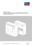
2.1 Appropriate Usage
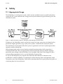
The Windy Boy is a wind power inverter, which converts rectified current of a small wind turbine
system into AC current and feeds this energy into the power distribution grid, domestic grid or the
stand-alone system.
Figure 1: Small wind turbine systems a Windy Boy and Windy Boy Protection Box.
Furthermore, the Windy Boy can be used as an inverter for power conversion units based on the
permanent magnet generators (e.g. hydro power systems, combined heat and power plant).
The manufacturer of the small wind turbine system or generator must have his plant approved for
operation with this Windy Boy.
When designing the system, ensure that the permitted operating range of all components is
maintained at all times. Also use appropriate protective measures to ensure that the maximum
permissible input voltage of the Windy Boy is not exceeded. SMA Solar Technology AG offers
corresponding components for this, e.g. the Windy Boy Protection Box.
Do not use the Windy Boy for purposes other than those described here. Alternative uses,
modifications, and the installation of components void the warranty claims and operation permit.
This guide is part of the Windy Boy. Follow all the tasks described in this guide. Keep this guide in a
convenient place for future reference.
6
WB1100LV-IA-IEN104130
Installation Guide
SMA Solar Technology AG
2 Safety
2.2 Safety Precautions
Danger to life due to high voltages.
• All work on the inverter may be carried out by qualified personnel only.
Danger of burn injuries due to hot enclosure parts.
• Only touch the lid during operation.
2.3 Explanation of Symbols
2.3.1 Symbols on the Inverter
Symbol
Description
Operation Display.
Indicates the operation condition of the inverter.
Ground fault or varistor defective.
There is either a ground fault in the system, or at least one of the varistors inside the
inverter is defective.
An error has occurred.
Read the installation guide and the user manual to remedy the malfunction.
Tap to switch on the display light and switch to the next message.
Installation Guide
WB1100LV-IA-IEN104130
7
2 Safety
SMA Solar Technology AG
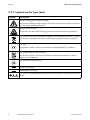
2.3.2 Symbols on the Type Label
Symbol
Description
Beware of dangerous electrical voltage.
The inverter operates at high voltages. All work on the inverter must be carried out
exclusively by qualified personnel.
Beware of hot surface.
The inverter can become hot during operation. Avoid contact during operation.
The inverter must not be disposed of together with the household waste. For more
information on disposal, see section 10.4 ”Disposing of the Inverter”, page 35.
CE mark.
The inverter complies with the requirements of the applicable EC guidelines.
RAL quality mark for solar products.
The inverter complies with the requirements of the German Institute for Quality
Assurance and Labeling.
The inverter has a transformer.
Direct Current (DC)
Alternating Current (AC)
The inverter is protected against penetration by dust particles and water jets from any
angle.
8
WB1100LV-IA-IEN104130
Installation Guide
SMA Solar Technology AG
3
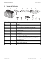
3 Scope of Delivery
Scope of Delivery
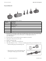
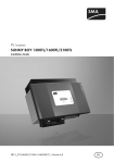
Figure 2: Components included in delivery
Position
Quantity
Description
A
1
Inverter
B
1
Wall mounting bracket
C
1
Set of documents with explanations and certificates
D
1
Supplementary sheet with factory settings
E
1
Installation Guide
F
1
User Manual
G
2
Cable gland
H
2
Counter nut for cable gland
I
1
AC connection socket: socket unit, threaded sleeve, pressure
screw PG16, sealing ring PG16, fastening case PG13.5,
cable gland PG16
K
1
Protective cap for AC socket
L
1
M6x12 cylinder head screw
M
1
Jumper
Installation Guide
WB1100LV-IA-IEN104130
9
4 Mounting the Inverter with the Wall Mounting Bracket
4
SMA Solar Technology AG
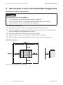
Mounting the Inverter with the Wall Mounting Bracket
Requirements for the mounting location:
Danger to life due to fire or explosion.
• Do not mount the inverter on flammable construction materials.
• Do not mount the inverter in areas where highly flammable materials are stored.
• Do not mount the inverter in areas with a risk of explosion.
☐ Mount on a solid surface.
☐ The mounting surface is suitable for the weight and dimensions of the inverter.
☐ The mounting location must be clear and have safe access without the use of additional aids
(such as scaffolding or lifting platforms) at all times.
☐ The mounting location must not be exposed to direct sunlight.
☐ Observe climatic conditions (see chapter 11 ”Technical Data”, page 36).
☐ Observe minimum clearance to the walls as well as to other inverters or other objects.
Minimum clearances:
Figure 3: Minimum clearances to be observed
10
WB1100LV-IA-IEN104130
Installation Guide
SMA Solar Technology AG
4 Mounting the Inverter with the Wall Mounting Bracket
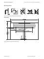
Mounting position:
Figure 4: Permitted and prohibited mounting positions
Dimensions:
Figure 5: Wall mounting bracket dimensioning
Installation Guide
WB1100LV-IA-IEN104130
11
4 Mounting the Inverter with the Wall Mounting Bracket
SMA Solar Technology AG
Risk of injury due to the heavy weight of the inverter.
• Note the weight of the inverter (see section 11 ”Technical Data”, page 36).
• Use fastening material suitable for the surface.
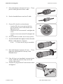
1. Mark the position of the drill holes. Use the wall mounting bracket when marking the holes.
2. Fasten the wall bracket using suitable fastening material.
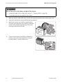
3. Attach the inverter in the wall mounting bracket
using the upper mounting clips. Make sure that the
inverter cannot be being pushed out of the wall
mounting bracket from the side.
4. To secure the inverter from lifted out, fasten the
inverter on the wall mounting bracket using the
provided M6x12 cylinder head screw.
12
WB1100LV-IA-IEN104130
Installation Guide
SMA Solar Technology AG
5
5 Electrical Connection
Electrical Connection
5.1 Overview of the Connection Area
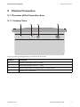
5.1.1 Exterior View
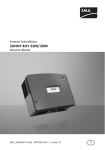
Figure 6: Enclosure openings and plug at the bottom of the inverter
Position
Description
A
Enclosure opening for the DC+ cable
B
Enclosure opening for the DC − cable
C
Enclosure opening with sealing plugs for communication
D
Socket for AC Connection
Installation Guide
WB1100LV-IA-IEN104130
13
5 Electrical Connection
SMA Solar Technology AG
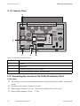
5.1.2 Interior View
Figure 7: Connections inside the inverter
Position
Description
A
Varistors
B
Jumper slot
C
Connection terminals for DC+ and DC −
D
Socket and connection area for communication
5.2 Connecting the Inverter to the Public Distribution Grid
Cable sizing:
☐ The conductor cross-section must be dimensioned so output losses do not exceed 1 % at nominal
power.
☐ Conductor cross-section is maximum 2.5 mm².
☐ Cable length is maximum 21 m for 1.5 mm² and maximum 35 m for 2.5 mm².
☐ External cable diameter is 9 mm … 17 mm.
14
WB1100LV-IA-IEN104130
Installation Guide
SMA Solar Technology AG
5 Electrical Connection
Load Disconnection Unit and Cable Protection:
• Install a separate line circuit breaker or load disconnection unit for each inverter to ensure that
the inverter can be safely disconnected under load. Here, observe the maximum permissible
fuse protection (see section 11 ”Technical Data”, page 36).
Detailed information and examples for the design of a line circuit breaker can be found in the
Technical Information "Line Circuit Breaker" in the download area at www.SMA.de/en.
Danger to life due to fire.
When more than one inverter is connected to the same line circuit breaker in parallel, the protective
function of the line circuit breaker is no longer guaranteed. It can result in a cable fire or the
destruction of the inverter.
• Do not connect more than one inverter to a line circuit breaker. Here, observe the maximum
permissible fuse protection (see section 11 ”Technical Data”, page 36).
Risk of lethal electric shock
When a generator (inverter) and a load are connected to the same line circuit breaker, the
protective function of the Line Circuit Breaker is no longer guaranteed. The current from the inverter
and the public electrical grid can accumulate to overcurrent which is not be detected by the line
circuit breaker.
• Always protect consumers separately.
• Never connect consumers between the inverter and the line circuit breaker without protection.
Damage to the inverter by using screw type fuse elements as a load disconnection unit!
A screw type fuse element (e.g. D system (Diazed) or D0 system (Neozed)) is not a load
disconnection unit. When disconnecting under load using a screw type fuse element, the inverter
can be damaged.
• Use a load disconnection switch or a line circuit breaker as a load disconnection unit.
Installation Guide
WB1100LV-IA-IEN104130
15
5 Electrical Connection
SMA Solar Technology AG
Required Materials
Figure 8: AC plug components (included in delivery)
Position
Description
A
Socket tube
B
Threaded sleeve
C
Sealing ring
D
Fastening case
E
Pressure screw
F
Cable gland
1. Check that the grid voltage is within the permissible voltage range. Here, observe the inverter's
exact operating range (see Technical Description of "Operating Parameters" at
www.SMA.de/en).
2. Disconnect the line circuit breaker and secure against re-connection.
3. Strip approx. 30 mm from the AC cable.
4. Shorten L and N by 5 mm.
5. Strip 4 mm … 5 mm of the L, N and PE wires.
6. If the cable diameter is 9 mm … 13.5 mm, use sealing ring, fastening case and pressure screw:
– Push the sealing ring into the fastening case.
– Pass the pressure screw and the fastening case
including the sealing ring over the AC cable.
16
WB1100LV-IA-IEN104130
Installation Guide
SMA Solar Technology AG
5 Electrical Connection
7. If the cable diameter is between 13.5 mm … 17 mm,
pass the cable gland over the AC cable.
8. Pass the threaded sleeve over the AC cable.
9. Connect PE, N and L to socket element:
– Insert the PE in the screw terminal with the
ground symbol on the socket element and
tighten the screw.
– Insert the N into screw terminal 1 and tighten the
screw.
– Insert the L into screw terminal 2 and tighten the
screw.
10. Check that the PE, N and L are securely in place.
11. Screw the threaded sleeve tightly onto the socket tube.
☑ If the cable diameter is between
9 mm … 13.5 mm, the AC plug is assembled.
12. If the cable diameter is between 13.5 mm … 17 mm,
tighten the cable gland lock nut firmly on the
threaded sleeve.
13. If the AC plug is not immediately connected to the
inverter, attach the protective cap onto the AC
socket on the inverter.
14. Insert the AC plug into the AC socket on the inverter
and tighten it.
Installation Guide
WB1100LV-IA-IEN104130
17
5 Electrical Connection
SMA Solar Technology AG
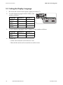
5.3 Setting the Display Language
1. Disconnect the inverter from the power supply (see section 7).
2. To set the display language for WB 1100LV, set the
switches as follows:
Language
Switch S2
Switch S1
German
B
B
English
B
A
French
A
B
Spanish
A
A
3. To set the display language for WB 1100LV-IT, set the switches as follows:
Language
Switch S2
Switch S1
Italian
B
A
English
A
A
4. Close the lid:
– Create a PE connection to the enclosure cover.
– Place the lid onto the enclosure and secure with 4 screws.
18
WB1100LV-IA-IEN104130
Installation Guide
SMA Solar Technology AG
5 Electrical Connection
5.4 Connecting the Small Wind Turbine System
Requirements:
☐ The AC line circuit breaker is switched off and secured so it cannot be reactivated.
☐ The small wind turbine system is stopped and secured so it will not restart.
Destruction of the inverter due to excessive power from the small wind turbine system.
All warranty claims become void.
• Observe the maximum power that can be connected
(see section 11 ”Technical Data”, page 36).
• Install overvoltage protection between the small wind turbine system and the inverter.
1. Remove the adhesive tape from the enclosure openings for DC+ and DC − .
2. Attach the cable glands on the enclosure openings for DC+ and DC − .
3. Unscrew the cable gland lock nuts and pass each cable gland over DC+ and DC − .
4.
Electrostatic discharges can damage the inverter.
Internal components of the inverter can be irreparably damaged by electrostatic discharge.
• Make sure you are grounded before touching any component.
5. Open the lid:
– Loosen all screws of the enclosure lid and carefully pull the lid forward.
– Disconnect the PE connection from the enclosure cover. Loosen the locking on the PE
connection on the lid.
6. Connect the cables to the + and − connection terminals. Ensure the connection terminals have
the correct polarity.
7. Tighten the lock nut onto the cable gland.
Installation Guide
WB1100LV-IA-IEN104130
19
5 Electrical Connection
SMA Solar Technology AG
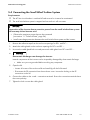
5.5 Communication
The inverter is equipped with a slot for communication interfaces, so that it can communicate using
special data acquisition devices (e.g. Sunny WebBox) or a PC with appropriate software.
Refer to the communication interface manual for a detailed wiring diagram and a mounting
description.
5.6 Changing the Country Data Set
Danger to life due to high voltages in the event of outage of the power distribution grid.
If the PV inverter is set to "OFF-Grid", it does not fulfill any country-specific standards and regulations.
If there is a public grid outage, there is a danger of feedback.
• If "OFF-Grid" is set, the inverter only operates in a stand-alone grid.
Changing the Country Data Set and grid-relevant Parameters
To change the country data set or grid-relevant parameters, you need a personal access code
- the SMA Grid Guard Code. The application form for the SMA Grid Guard Code is located
in the download area at www.SMA.de/en, in the "Certificate" category.
• If the inverter's factory-set country data set does not apply to your country, set the country data
set with a communication product using the "Default" parameter. HINT: You can see which
country data set was set at the factory on the type label and the supplementary document
provided with the factory settings.
20
WB1100LV-IA-IEN104130
Installation Guide
SMA Solar Technology AG
5 Electrical Connection
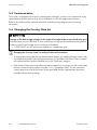
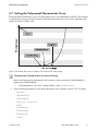
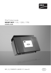
5.7 Setting the Polynomial Characteristic Curve
The polynomial characteristic curve is an adjustable power curve depending on the DC input voltage.
To optimize the energy yield, the inverter's polynomial characteristic curve must be adjusted to the
small wind turbine system used.
Figure 9: The feed-in AC power in relation to the inverter's DC input voltage.
Communication Problems due to incorrect Setting
Before transferring the set parameters to the inverter, make sure that the "UdcWindStart" is
greater than "UdcWindStop".
• If "UdcWindStart" is less than "UdcWindStop", reduce "UdcWindStop".
• Set the following parameters with Windy Boy Setup Tool, software version 1.0.5 or higher:
– "Vpv-Start"
– "UdcWindStart"
– "UdcWindStop"
– "Wind_a0" … "Wind_a3"
– "Pmax"
– "P-Wind-Ramp"
– "KP-Wind-Reg"
– "KI-Wind-Reg"
– "T-Stop"
Installation Guide
WB1100LV-IA-IEN104130
21
6 Commissioning
6
SMA Solar Technology AG
Commissioning
Requirements:
☐ The inverter is mounted correctly.
☐ All cables are correctly connected.
☐ The line circuit breaker is correctly rated.
☐ The small wind turbine system is grounded according to the manufacturer specifications.
☐ The rectifier and overvoltage protection are installed between the small wind turbine system and
the inverter.
1. Close the lid:
– Create a PE connection to the enclosure cover.
– Place the lid onto the enclosure and secure with 4 screws.
2. Switch on the line circuit breaker.
3. Commission the small wind turbine system in accordance with the instructions of the
manufacturer.
☑ Green LED is illuminated.
✖ Is green LED flashing?
The wind is currently too weak. The inverter begins to operate as the wind becomes stronger.
✖ Is the red or yellow LED illuminated or blinking?
An error or fault may have occurred.
• Eliminate the error or fault (see section 9 ”Troubleshooting”, page 25).
22
WB1100LV-IA-IEN104130
Installation Guide
SMA Solar Technology AG
7
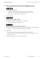
7 Disconnect the Inverter from Voltage Sources
Disconnect the Inverter from Voltage Sources
1.
Risk of lethal electric shock.
• Disconnect the line circuit breaker and secure against re-connection.
• Stop the small wind turbine system and secure it so that it cannot restart.
• Ensure that no voltage is present on the DC side.
2. Pull out the AC plug.
3.
Danger to life due to high voltages.
The capacitors in the inverter require 15 minutes to discharge.
• Wait 15 minutes before opening the lid.
4.
Electrostatic discharges can damage the inverter.
Internal components of the inverter can be irreparably damaged by electrostatic discharge.
• Make sure you are grounded before touching any component.
5. Open the lid:
– Loosen all screws of the enclosure lid and carefully pull the lid forward.
– Disconnect the PE connection from the enclosure cover. Loosen the locking on the PE
connection on the lid.
6. Remove the cables from the + and − connection terminals.
Installation Guide
WB1100LV-IA-IEN104130
23
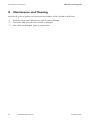
8 Maintenance and Cleaning
8
SMA Solar Technology AG
Maintenance and Cleaning
Impurities (e.g. dust or pollen) can cause heat accumulation, which can lead to yield losses.
1. Check the inverter and cables for any signs of external damage.
2. Contact the SMA Serviceline if the inverter is damaged.
3. If the cables are damaged, repair or replace them.
24
WB1100LV-IA-IEN104130
Installation Guide
SMA Solar Technology AG
9
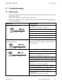
9 Troubleshooting
Troubleshooting
9.1 Blink Codes
• If the inverter displays blink codes other than those described in the following section, contact
the SMA Serviceline.
• Only perform the repair work described in this section.
• If the inverter is defective, use the replacement and repair service from SMA Solar Technology AG
(see www.SMA.de/en).
Blink code
Fault indication
The yellow LED blinks twice
< ACVtgRPro >
(Remedy see ”ACVtgRPro”, page 27)
< Fac-Bfr > (Remedy see ”Fac-Bfr”, page 28)
< Fac-Srr > (Remedy see ”Fac-Srr”, page 28)
< FacFast > (Remedy see ”FacFast”, page 28)
< Vac-Bfr > (Remedy see ”Vac-Bfr”, page 30)
< Vac-Srr > (Remedy see ”Vac-Srr”, page 31)
Yellow LED flashes 4 times and the display
background flashes
< !PV-Overvoltage! - !DISCONNECT DC! >
(Remedy see ”!PV-Overvoltage! - !DISCONNECT
DC!”, page 26)
The yellow LED blinks 5 times
< Bfr-Srr > (Remedy see ”Bfr-Srr”, page 27)
< EEPROM > (Remedy see ”EEPROM”, page 27)
< EEPROM dBh >
(Remedy see ”EEPROM dBh”, page 27)
< EeRestore > (Remedy see ”EeRestore”, page 27)
< Imax > (Remedy see ”Imax/Overcurrent”, page 28)
< K1-Close >
(Remedy see ”K1-Close”, page 28)
< K1-Open > (Remedy see ”K1-Open”, page 28)
< Offset > (Remedy see ”Offset”, page 29)
< ROM > (Remedy see ”ROM”, page 29)
< Shut-Down >
(Remedy see ”Shut-Down”, page 29)
Installation Guide
WB1100LV-IA-IEN104130
25
9 Troubleshooting
SMA Solar Technology AG
Blink code
Fault indication
Yellow LED is continuously illuminated
< MSD-Fac >
(Remedy see ”MSD-Fac”, page 29)
< MSD-Vac >
(Remedy see ”MSD-Vac”, page 29)
< MSD-Timeout >
(Remedy see ”MSD-Timeout”, page 29)
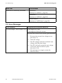
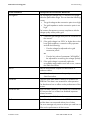
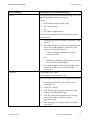
9.2 Error Messages
Fault indication
Description and Corrective Measures
!PV-Overvoltage! - !DISCONNECT DC! Overvoltage at DC input!
Overvoltage can destroy the inverter.
Disconnect the inverter from the public grid immediately:
1. Disconnect the inverter from voltage sources
(see section 7).
2. Check DC voltage.
3. If the DC voltage is above the maximum input
voltage, check the plant design.
4. If the DC is below the maximum input voltage,
connect the small wind turbine system
(see section 5.4).
5. If the message occurs again, contact the
SMA Serviceline.
26
WB1100LV-IA-IEN104130
Installation Guide
SMA Solar Technology AG
9 Troubleshooting
Fault indication
Description and Corrective Measures
ACVtgRPro
The average grid voltage over 10 minutes is no longer
within the permissible range. This can have the following
causes:
• The grid voltage at the connection point is too high.
• The grid impedance at the connection point is too
high.
The inverter disconnects to assure compliance with the
voltage quality of the public grid.
1. Check the grid voltage at the point of connection of
the inverter:
2. If the grid voltage is at 253 V or higher due to the
local grid conditions, contact the utility operator
and ask the following:
– Can the voltage be adjusted to the grid
connection point?
or
– Can the limit value of parameter "ACVtgRPro"
be adjusted for monitoring the voltage quality?
3. If the grid voltage is continually within the
acceptable range and the error still occurs, contact
the SMA Serviceline.
Bfr-Srr
Internal measurement comparison disturbance or
hardware defect.
• If this disturbance occurs frequently, contact the
SMA Serviceline.
EEPROM
Transition fault while data is read out or written from
EEPROM. This data is not essential for safe operation.
The disturbance has no effect on the performance of the
inverter.
EEPROM dBh
EEPROM data is defective. The inverter has switched itself
off, because the loss of data has disabled important
inverter functions.
• Contact the SMA Serviceline.
EeRestore
One of the duplicate data sets in the EEPROM is defective
and has been reconstructed without loss of data.
The error message only serves to inform you and has no
effect on the performance of the inverter.
Installation Guide
WB1100LV-IA-IEN104130
27
9 Troubleshooting
SMA Solar Technology AG
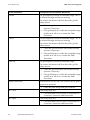
Fault indication
Description and Corrective Measures
Fac-Bfr
The grid frequency has left the allowable range. "Bfr" is
an internal message and has no meaning.
The inverter disconnects itself from the public grid for
safety reasons.
• Check the grid connection and contact the utility
operator if necessary.
• If the grid frequency is within the acceptable range
and the error still occurs, contact the SMA
Serviceline.
Fac-Srr
The grid frequency has left the allowable range. "Srr" is
an internal message and has no meaning.
The inverter disconnects itself from the public grid for
safety reasons.
• Check the grid connection and contact the utility
operator if necessary.
• If the grid frequency is within the acceptable range
and the error still occurs, contact the SMA
Serviceline.
FacFast
The grid frequency has left the allowable range.
The inverter disconnects itself from the public grid for
safety reasons.
• Check the grid connection and contact the utility
operator if necessary.
• If the grid frequency is within the acceptable range
and the error still occurs, contact the SMA
Serviceline.
Imax/Overcurrent
Overcurrent on the AC side. The current in the AC grid is
greater than specified.
K1-Close
Fault during relay test.
• Check the plant design and grid conditions.
• If this disturbance occurs often or several times in
succession, contact the SMA Serviceline.
K1-Open
Fault during relay test.
• If this disturbance occurs often or several times in
succession, contact the SMA Serviceline.
28
WB1100LV-IA-IEN104130
Installation Guide
SMA Solar Technology AG
9 Troubleshooting
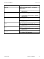
Fault indication
Description and Corrective Measures
MSD-Fac
Internal measurement comparison disturbance or
hardware defect.
• If this disturbance occurs frequently, contact the
SMA Serviceline.
MSD-Vac
Internal measurement comparison disturbance or
hardware defect.
• If this disturbance occurs frequently, contact the
SMA Serviceline.
MSD-Timeout
Internal measurement comparison disturbance or
hardware defect.
• If this disturbance occurs frequently, contact the
SMA Serviceline.
Offset
Fault in the acquisition of measurement data.
• If this disturbance occurs frequently, contact the
SMA Serviceline.
ROM
Problem accessing the memory.
• If this disturbance occurs frequently, contact the
SMA Serviceline.
Shut-Down
Temporary inverter disturbance.
• Contact the SMA Serviceline.
Installation Guide
WB1100LV-IA-IEN104130
29
9 Troubleshooting
SMA Solar Technology AG
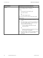
Fault indication
Description and Corrective Measures
Vac-Bfr
The grid voltage has left the allowable range. "Bfr" is an
internal message and has no meaning.
Causes:
• Disconnection from the public grid
• AC cable is broken
or
• AC cable is highly resistive
The inverter disconnects itself from the public grid for
safety reasons.
1. Check the grid current and grid connection on the
inverter.
2. If the grid voltage is outside the permissible range
due to local grid conditions, contact the utility
operator and ask the following:
– Can the voltage be adjusted to the grid
connection point?
or
– May the monitored operational limits "Vac-Min"
and "Vac-Max" be changed?
3. If the grid voltage is within the acceptable range
and the error still occurs, contact the SMA
Serviceline.
30
WB1100LV-IA-IEN104130
Installation Guide
SMA Solar Technology AG
9 Troubleshooting
Fault indication
Description and Corrective Measures
Vac-Srr
The grid voltage has left the allowable range. "Srr" is an
internal message and has no meaning.
Causes:
• Disconnection from the public grid
• AC cable is broken
or
• AC cable is highly resistive.
The inverter disconnects itself from the public grid for
safety reasons.
1. Check the grid current and grid connection on the
inverter.
2. If the grid voltage is outside the permissible range
due to local grid conditions, contact the utility
operator and ask the following:
– Can the voltage be adjusted to the grid
connection point?
or
– May the monitored operational limits "Vac-Min"
and "Vac-Max" be changed?
3. If the grid voltage is within the acceptable range
and the error still occurs, contact the SMA
Serviceline.
VpvMax
Overvoltage at DC input!
Overvoltage can destroy the inverter.
Disconnect the inverter from the public grid immediately:
1. Disconnect the inverter from voltage sources
(see section 7).
2. Check DC voltage.
3. If the DC voltage is above the maximum input
voltage, check the plant design.
4. If the DC is below the maximum input voltage,
connect the small wind turbine system
(see section 5.4).
5. If the message occurs again, contact the SMA
Serviceline.
Installation Guide
WB1100LV-IA-IEN104130
31
9 Troubleshooting
SMA Solar Technology AG
Fault indication
Description and Corrective Measures
Watchdog
Internal program run fault.
• If this disturbance occurs frequently, contact the
SMA Serviceline.
Watchdog-Srr
Internal program run fault.
• If this disturbance occurs frequently, contact the
SMA Serviceline.
32
WB1100LV-IA-IEN104130
Installation Guide
SMA Solar Technology AG
9 Troubleshooting
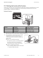
9.3 Checking the Function of the Varistors
Varistors are wear parts. Their functional efficiency diminishes with age or repeated strain as a result
of overvoltage. It is therefore possible that one of the thermally monitored varistors has lost its
protective function, and thus the red LED is lit.
Position of Varistors
Position
Description
Varistor connection
A
Outer terminal
With loop or crimp
B
Middle terminal
Without loop or crimp
C
Outer terminal
Without loop or crimp
1. Disconnect the inverter from the power supply (see section 7).
2. Use a multimeter to check all the varistors in their
installed state to ascertain whether there is a
conducting connection between the middle and
outer terminal.
☑ There is no conducting connection.
– The respective varistor is not working and must
be replaced. SMA Solar Technology AG
recommends that you replace both varistors.
✖ Is there a conducting connection?
There is probably a different fault in the inverter.
• Contact the SMA Serviceline.
Installation Guide
WB1100LV-IA-IEN104130
33
9 Troubleshooting
SMA Solar Technology AG
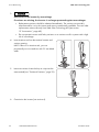
3.
Destruction of the inverter by overvoltage.
If varistors are missing, the inverter is no longer protected against overvoltages.
• Replacement varistors should be obtained immediately. The varistors are specially
manufactured for use in the inverter and are not commercially available. You can order
replacement varistors directly from SMA Solar Technology AG (see section
12 ”Accessories”, page 40).
• Do not operate inverters with faulty varistors or no varistors at all in systems with a high
risk of overvoltage.
4. Insert insertion tool into the terminal contact and
varistor opening.
HINT: If there is no insertion tool, you can
provisionally use a screwdriver with 3.5 mm blade
width.
5. Insert new varistor. Insert the loop or crimp into the
outer terminal (see ”Position of Varistors”, page 33).
6. Commission the inverter (see section 6).
34
WB1100LV-IA-IEN104130
Installation Guide
SMA Solar Technology AG
10 Decommissioning
10 Decommissioning
10.1 Dismantling the Inverter
Risk of injury due to the heavy weight of the inverter.
• Note the weight of the inverter (see section 11 ”Technical Data”, page 36).
1. Disconnect the inverter from the power supply (see section 7).
2. Close the lid:
– Create a PE connection to the enclosure cover.
– Place the lid onto the enclosure and secure with 4 screws.
3. Loosen the screw between the inverter and the wall mounting bracket.
4. Lift the inverter off the wall mounting bracket.
10.2 Packaging the Inverter
• Package the inverter in the original packaging if it is available.
• If the original packaging is not available, use a box that is suitable for the weight and
dimensions of the inverter.
10.3 Storing the Inverter
Requirements for the storage location:
☐ The storage location is dry.
☐ The ambient temperature is between − 25 °C and +60 °C.
10.4 Disposing of the Inverter
• Dispose of the inverter in accordance with the applicable disposal regulations for electronic
waste.
or
• Return the inverter to SMA Solar Technology AG, assuming shipping costs. When doing so,
label the packaging "ZUR ENTSORGUNG" ("FOR DISPOSAL").
Installation Guide
WB1100LV-IA-IEN104130
35
11 Technical Data
SMA Solar Technology AG
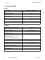
11 Technical Data
DC Input
Turbine control
Maximum DC power at cos ϕ = 1
Maximum DC voltage
Voltage range at AC nominal power
Polynomial characteristic curve
1 240 W
60 V
21 V ... 60 V
DC nominal voltage
25 V
Minimum DC voltage at 230 V AC
21 V
Start voltage, adjustable
21 V
Maximum input current
62 A
Maximum input current per input
62 A
AC Output
Nominal AC power at 230 V, 50 Hz
1 000 W
Maximum AC apparent power
1 000 VA
Nominal AC voltage
Nominal AC current at 230 V
Maximum AC current
Harmonic distortion of output current at
220 V/230 V/240 V
4.4 A
5A
≤ 3%
AC THD voltage < 2 %,
AC power > 0.5 nominal AC power
AC voltage range
AC side
160 V ... 260 V
50 Hz/60 Hz
Operating range at AC grid frequency 50 Hz
45.5 Hz … 54.5 Hz
Operating range at AC grid frequency 60 Hz
55.5 Hz … 64.5 Hz
cos ϕ at nominal AC power
1
Supply phases
1
Connection phases
1
Overvoltage category
III
36
WB1100LV-IA-IEN104130
Installation Guide
SMA Solar Technology AG
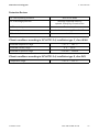
11 Technical Data
Protective Devices
DC reverse-polarity protection
DC overvoltage protection
Short circuit diode
Thermally monitored varistors/
optional: Windy Boy Protection Box
AC short circuit protection
Personnel protection
Galvanic isolation
Current control
Insulation monitoring: Riso > 1 M Ω
Available
Climatic conditions according to IEC 60721-3-4, installation type C, class 4K4H
Extended temperature range
Extended humidity range
Extended air pressure range
− 25 °C … +60 °C
0 % … 100 %
79.5 kPa … 106 kPa
Climatic conditions according to IEC 60721-3-4, installation type E, class 2K3
Temperature range
Installation Guide
− 25 °C … +70 °C
WB1100LV-IA-IEN104130
37
11 Technical Data
SMA Solar Technology AG
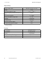
General Data
Width x height x depth
440 mm x 299 mm x 214 mm
Weight
29 kg
Operating temperature range
− 25 °C … +60 °C
Maximum operating altitude above mean sea
level
Noise emission (typical)
2 000 m
≤ 33 dB(A)
Internal consumption in night mode
0.1 W
Topology
LF transformer
Cooling concept
Convection
Electronics protection degree*
Connection area protection degree
IP 65
**
IP 65
* according to IEC 60529
according to IEC 62103
** Features
DC connection
Spring-type terminal
AC connection
AC plug connector
Display
LC text display
®
Bluetooth Wireless Technology
Optional
RS485, galvanically isolated
Standard
38
WB1100LV-IA-IEN104130
Installation Guide
SMA Solar Technology AG
11 Technical Data
Grid forms
IT grid
Suitable
TN-C grid
Suitable
TN-S grid
Suitable
TT grid, if UN_PE < 30 V
Suitable
Efficiency
Peak efficiency
European efficiency
Installation Guide
92 %
90.4 %
WB1100LV-IA-IEN104130
39
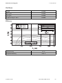
12 Accessories
SMA Solar Technology AG
12 Accessories
The following table contains the corresponding accessory and spare parts for your inverter. If
required, you can order these from SMA Solar Technology AG or your dealer.
Description
Brief description
SMA order number
Replacement varistors
2 thermally monitored varistors,
including insertion tool
SB-TV4
Installation tool for varistors
Tool for installing the varistors
SB-TVWZ
RS485 upgrade kit
RS485 interface
485PB-NR
Bluetooth upgrade kit
Bluetooth interface
BTPBINV-NR
40
WB1100LV-IA-IEN104130
Installation Guide
SMA Solar Technology AG
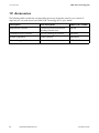
13 Contact
13 Contact
If you have technical problems concerning our products, contact the SMA Serviceline. We require the
following information in order to provide you with the necessary assistance:
• Type (see "Type/Model" on type label)
• Series number (see "Serial No." on the type label)
• Type of connected small wind turbine system
• Communication type
• Blink code or display message of the inverter
SMA Solar Technology AG
Sonnenallee 1
34266 Niestetal, Germany
www.SMA.de
SMA Serviceline
Inverters:
+49 561 9522 1499
Communication: +49 561 9522 2499
Fax:
+49 561 9522 4699
E-Mail:
[email protected]
Installation Guide
WB1100LV-IA-IEN104130
41
Notes
42
MA Solar Technology AG
WB1100LV-IA-IEN104130
Installation Guide
SMA Solar Technology AG
Legal Restrictions
The information contained in this document is the property of SMA Solar Technology AG. Publishing its content, either partially or
in full, requires the written permission of SMA Solar Technology AG. Any internal company copying of the document for the
purposes of evaluating the product or its correct implementation is allowed and does not require permission.
Exclusion of liability
The general terms and conditions of delivery of SMA Solar Technology AG shall apply.
The content of these documents is continually checked and amended, where necessary. However, discrepancies cannot be
excluded. No guarantee is made for the completeness of these documents. The latest version is available online at www.SMA.de
or from the usual sales channels.
Guarantee or liability claims for damages of any kind are excluded if they are caused by one or more of the following:
• Damages during transportation
• Improper or inappropriate use of the product
• Operating the product in an unintended environment
• Operating the product whilst ignoring relevant, statutory safety regulations in the deployment location
• Ignoring safety warnings and instructions contained in all documents relevant to the product
• Operating the product under incorrect safety or protection conditions
• Altering the product or supplied software without authority
• The product malfunctions due to operating attached or neighboring devices beyond statutory limit values
• In case of unforeseen calamity or force majeure
The use of supplied software produced by SMA Solar Technology AG is subject to the following conditions:
• SMA Solar Technology AG rejects any liability for direct or indirect damages arising from the use of software developed by
SMA Solar Technology AG. This also applies to the provision or non-provision of support activities.
• Supplied software not developed by SMA Solar Technology AG is subject to the respective licensing and liability agreements
of the manufacturer.
SMA Factory Warranty
The current guarantee conditions come enclosed with your device. These are also available online at www.SMA.de and can be
downloaded or are available on paper from the usual sales channels if required.
Trademarks
All trademarks are recognized even if these are not marked separately. Missing designations do not mean that a product or brand
is not a registered trademark.
The Bluetooth® word mark and logos are registered trademarks owned by Bluetooth SIG, Inc. and any use of such marks by SMA
Solar Technology AG is under license.
SMA Solar Technology AG
Sonnenallee 1
34266 Niestetal
Germany
Tel. +49 561 9522-0
Fax +49 561 9522-100
www.SMA.de
E-Mail: [email protected]
© 2004 to 2010 SMA Solar Technology AG. All rights reserved
Installation Guide
WB1100LV-IA-IEN104130
43
4."4PMBS5FDIOPMPHZ
XXX4."4PMBSDPN
4."4PMBS5FDIOPMPHZ"(
XXX4."EF
4.""NFSJDB--$
XXX4.""NFSJDBDPN
4."5FDIOPMPHZ"VTUSBMJB1UZ-UE
XXX4.""VTUSBMJBDPNBV
4."#FOFMVY413XXX4."#FOFMVYDPN
4."#FJKJOH$PNNFSDJBM$P-UE
XXX4."$IJOBDPN
4."$[FDI3FQVCMJDTSP
XXX4."$[FDIDPN
4."'SBODF4"4
XXX4."'SBODFDPN
4.")FMMBT"&
XXX4.")FMMBTDPN
4."*C©SJDB5FDOPMPHB4PMBS4-
XXX4."*CFSJDBDPN
4."*UBMJB4SM
XXX4."*UBMJBDPN
4."5FDIOPMPHZ,PSFB$P-UE
XXX4.",PSFBDPN