1
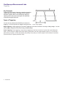
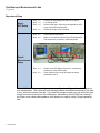
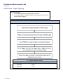
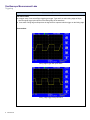
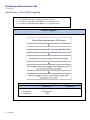
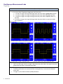
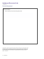
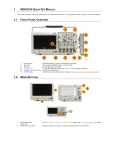
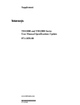
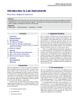
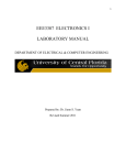
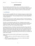
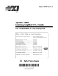
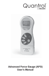
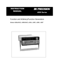
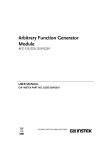
Oscilloscope Measurement Labs Triggering the Signal - Edge and Pulse Width Triggering This lab exercise teaches general oscilloscope triggering and how to use edge triggering and pulsewidth triggering, especially on a TDS2000 or TBS1000 Series oscilloscope. Objectives At the end of this laboratory session, you will be able to: Understand the basics of trigger systems / functions. Use edge trigger to capture a signal with rising or falling voltage Capture a signal when pulse width = or ≠ specified value Capture a signal when pulse width > or < specified value Equipment To carry out this experiment, you will need: Arbitrary Function Generator (Tektronix AFG3022 or equivalent) signal generator Oscilloscope (Tektronix TBS1022, TDS2002, or equivalent) 50Ω BNC cable 50Ω BNC feed-through terminator (optional) Theory To perform this experiment, you should be familiar with: Oscilloscope user manual – vertical system and amplitude measurement XYZs of Oscilloscopes – Page 27, section: Trigger System and Controls XYZs of Oscilloscopes – Page 29, section: Trigger Position XYZs of Oscilloscopes – Page 29, section: Trigger Sources XYZs of Oscilloscopes – Page 30, section: Trigger Modes 1 Lab Exercise Oscilloscope Measurement Labs Triggering Key Concepts: Triggering is the process of capturing a waveform based on various criteria you specify. The trigger makes repetitive waveforms appear static on the oscilloscope display by capturing at the same point in the signal and repeatedly overwriting the signal with itself. Types of Triggering: You can use any channel (Ch1/Ch2/Ext) as a source for triggering. You can only have one trigger at any given time. Figure 1. Edge Triggering Edge Triggering: Edge triggering is a process of triggering on the first occurrence of a rising or falling voltage. You can set the trigger voltage level and choose rising of falling voltage. Pulse Triggering. Pulse triggering, is a process of triggering on the first occurrence of a pulse with a specified pulse width. You can choose to trigger when pulse width is greater than, less than, approximately equal to, or not equal to a pulse width you specify. You can also specify the polarity of the pulse you want to capture, that is whether it is positive (rises then falls) or negative (falls then rises). 2 Lab Exercise Oscilloscope Measurement Labs Triggering Check Your Understanding Answer the following: 1. 2. 3. 4. 3 Triggering is required (Check all that apply) a. To make a signal appear clearly on the display b. To display a specific part of a signal on the display c. To make dynamic signal look static on the display d. To acquire a signal with specific characteristics Which of the following Trigger type is not present in TBS1000 or TDS2000 Series oscilloscope? a. Pulse width b. Glitch c. Edge d. Video If you have an oscilloscope that captures 10 horizontal divisions, and a signal is acquired with horizontal resolution of 50µS/div, what is the total duration of the acquired waveform? a. b. 500 µS 50 µS c. 5 µS d. 0.500 µS A sinusoid is acquired with a horizontal scale/resolution of 1mS/div. What would the frequency of this sine wave be if 3 cycles occupy 2.4 horizontal divisions? a. b. 125 Hz 1250 Hz c. 416.7 Hz d. 1k Hz Lab Exercise Oscilloscope Measurement Labs Triggering Experiment Setup Step 1: DUT Setup Step - 1.2 : Step - 1.3 : Step - 1.4 : Step - 1.5 : Connect the AFG/Signal Generator to AC power. Turn ON the AFG. Set the signal type, frequency and amplitude on AFG as per experiment requirements. Enable the output on AFG channel Step - 2.1 : Step - 2.2 : Power ON the oscilloscope. Make the connection between Signal Generator/AFG and oscilloscope as shown in the below picture. Step - 2.3 : Output of the AFG/Signal Generator is connected to Channel #1 of the oscilloscope* Press Autoset on the scope to display the signal generated by AFG Step 2: Measurement Setup Step - 2.4 : * Note: A 2 Vp-p setting on most signal generators will produce 4 Vp-p into the 1 MΩ inputs on most oscilloscopes. This is because most signal generators are calibrated assuming a 50Ω load. It won’t affect the outcome of the lab. If you want the settings to match, you can add a 50Ω feedthrough terminator to the input of the oscilloscope. Alternatively, the AFG3022 has a setting in the Output menu called Load Impedance, that allows you to specify a High Z (high impedance) load. 4 Lab Exercise Oscilloscope Measurement Labs Triggering Lab Exercise – Edge Triggering For the given signal: 1. To understand the basics of trigger systems / functions 2. To use edge trigger for capturing a signal when amplitude rises above / fall below a defined amplitude Procedure / Algorithm Signal Type Amplitude Frequency 5 Lab Exercise AFG / Signal Generator Setting Channel # 1 Square wave 2 Vp-p* 1 kHz Channel # 2 - Oscilloscope Measurement Labs Triggering Observations (Execution) We observe that: In trigger setup, if we select Edge triggering as trigger Type and if we select rising edge as Slope, then the signal trigger point will be on the Rising edge of the waveform. If we select Falling edge as Slope then the signal will be captured with the trigger on the falling edge. Screenshots: Rising edge trigger with pulse wave Falling edge trigger with pulse wave 6 Lab Exercise Oscilloscope Measurement Labs Triggering Rising edge trigger with sine wave Falling edge trigger with sine wave With this experiment, we learned: How to use the trigger function on the oscilloscope to trigger on the positive or negative edge of a signal. In real-life applications, we can use this concept: To analyze the seismic waves from the earth to for early detection of an earthquake To capture a stable waveform even with noisy / irregular wave shape. Oscilloscopes that are capable of advanced triggering are ideal for troubleshooting glitches, timing violations, overvoltage and dropouts in analogue and digital circuits. 7 Lab Exercise Oscilloscope Measurement Labs Triggering Lab Exercise – Pulse Width Triggering For the given signal: 1. To understand the basics of trigger systems / functions 2. To capture a signal when pulse width is = or ≠ specified value 3. To capture a signal when pulse width is > or < specified value Procedure / Algorithm AFG / Signal Generator Setting Signal Type Amplitude Frequency 8 Lab Exercise Channel # 1 Square wave 2 volt (pk-pk) 1 kHz Channel # 2 - Oscilloscope Measurement Labs Triggering Observations (Execution) We observe that: If we select Pulse Triggering as trigger type, and if we select 1. ‘>’ as when to trigger, then signal will trigger when the pulse width is greater than specified. 2. ‘<’ as when to trigger, then signal will trigger when the pulse width is less than specified. 3. ‘=’ as when to trigger, then signal will trigger when the pulse width is equal to (within 5%) specified. 4. ‘≠’ as when to trigger, then signal will trigger when the pulse width is not equal (not within 5%) to specified. Screenshots: a) Pulse width is greater than specified value b)Pulse width is less than specified value c) Pulse width is equal to specified value d) Pulse width is not equal to specified value With this experiment, we learned: How to use the trigger function to trigger a signal when the pulse width of the signal is less than, greater than and equal to a specified pulse width. In real-life applications, we can use this concept: To look for pulses those are narrower than the normal (glitches) on microcontroller data and control lines. To trigger on pulse width modulation (PWM) waveforms. 9 Lab Exercise Oscilloscope Measurement Labs Triggering Post-Lab Assessment Answer the following: 1. List the concepts you have learned doing this exercise. _____________________________________________ _____________________________________________ _ _ _ _ _ _ _ _ _ _ _ _ _ _ _ __ _ _ _ _ _ _ _ _ _ _ _ _ _ _ _ _ _ _ _ _ _ _ _ _ _ _ _ _ Copyright © 2013, Tektronix. All rights reserved. Tektronix products are covered by U.S. and foreign patents, issued and pending. Information in this publication supersedes that in all previously published material. Specification and price change privileges reserved. TEKTRONIX and TEK are registered trademarks of Tektronix, Inc.All other trade names referenced are the service marks, trademarks or registered trademarks of their respective companies. 04/2013 10 48W-29161-1 Lab Exercise