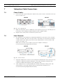
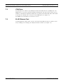
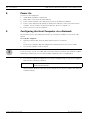
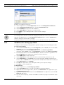
1
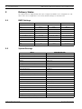
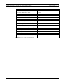
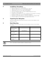
RAID Subsystem DVA-08K and DVA-16K
DVA-08K | DVA-16K
en
Quick Installation Guide
RAID Subsystem DVA-08K and DVA-16K | Quick Installation Guide
Table of Contents | en
3
Table of Contents
1
Precautions . . . . . . . . . . . . . . . . . . . . . . . . . . . . . . . . . . . . . . . . . . . . . . . . . . . . . . . . . . . . . . . . . . . . . . . 5
2
2.1
2.2
Delivery Status . . . . . . . . . . . . . . . . . . . . . . . . . . . . . . . . . . . . . . . . . . . . . . . . . . . . . . . . . . . . . . . . . . . . 6
RAID Settings . . . . . . . . . . . . . . . . . . . . . . . . . . . . . . . . . . . . . . . . . . . . . . . . . . . . . . . . . . . . . . . . . . . . . 6
System Settings . . . . . . . . . . . . . . . . . . . . . . . . . . . . . . . . . . . . . . . . . . . . . . . . . . . . . . . . . . . . . . . . . . . 6
3
Installation Procedures . . . . . . . . . . . . . . . . . . . . . . . . . . . . . . . . . . . . . . . . . . . . . . . . . . . . . . . . . . . . . . 8
4
Unpacking the Subsystem . . . . . . . . . . . . . . . . . . . . . . . . . . . . . . . . . . . . . . . . . . . . . . . . . . . . . . . . . . . . 8
5
Rack Mounting. . . . . . . . . . . . . . . . . . . . . . . . . . . . . . . . . . . . . . . . . . . . . . . . . . . . . . . . . . . . . . . . . . . . . 8
6
Drive Tray Installation . . . . . . . . . . . . . . . . . . . . . . . . . . . . . . . . . . . . . . . . . . . . . . . . . . . . . . . . . . . . . . . 9
7
7.1
7.2
7.3
7.4
Subsystem Cable Connections . . . . . . . . . . . . . . . . . . . . . . . . . . . . . . . . . . . . . . . . . . . . . . . . . . . . . .
Power Cables . . . . . . . . . . . . . . . . . . . . . . . . . . . . . . . . . . . . . . . . . . . . . . . . . . . . . . . . . . . . . . . . . . .
Host Channels . . . . . . . . . . . . . . . . . . . . . . . . . . . . . . . . . . . . . . . . . . . . . . . . . . . . . . . . . . . . . . . . . . .
COM Ports. . . . . . . . . . . . . . . . . . . . . . . . . . . . . . . . . . . . . . . . . . . . . . . . . . . . . . . . . . . . . . . . . . . . . .
RJ-45 Ethernet Port. . . . . . . . . . . . . . . . . . . . . . . . . . . . . . . . . . . . . . . . . . . . . . . . . . . . . . . . . . . . . . .
8
Power On . . . . . . . . . . . . . . . . . . . . . . . . . . . . . . . . . . . . . . . . . . . . . . . . . . . . . . . . . . . . . . . . . . . . . . . 12
9
Configuring the Host Computer via a Network . . . . . . . . . . . . . . . . . . . . . . . . . . . . . . . . . . . . . . . . . . . 12
10
10.1
10.2
Changing the Configuration via a Web Browser . . . . . . . . . . . . . . . . . . . . . . . . . . . . . . . . . . . . . . . . . . 13
Changing an IP Address . . . . . . . . . . . . . . . . . . . . . . . . . . . . . . . . . . . . . . . . . . . . . . . . . . . . . . . . . . . . 13
Guidelines for Setting Up a RAID . . . . . . . . . . . . . . . . . . . . . . . . . . . . . . . . . . . . . . . . . . . . . . . . . . . . . 14
11
11.1
11.2
11.3
Using Bosch RAIDWatch on the Host Computer . . . . . . . . . . . . . . . . . . . . . . . . . . . . . . . . . . . . . . . . . .
System requirements . . . . . . . . . . . . . . . . . . . . . . . . . . . . . . . . . . . . . . . . . . . . . . . . . . . . . . . . . . . . . .
Installing Bosch RAIDWatch on a Windows Platform . . . . . . . . . . . . . . . . . . . . . . . . . . . . . . . . . . . . . .
Changing Configuration. . . . . . . . . . . . . . . . . . . . . . . . . . . . . . . . . . . . . . . . . . . . . . . . . . . . . . . . . . . . .
16
16
17
18
12
12.1
12.2
12.3
Connecting a
Connecting a
Connecting a
Connecting a
19
19
21
23
Bosch Security Systems
.
.
.
.
.
Digital Video Recorder. . . . . . . . . . . . . . . . . . . . . . . . . . . . . . . . . . . . . . . . . . . . . . . . . . .
DiBos 8 . . . . . . . . . . . . . . . . . . . . . . . . . . . . . . . . . . . . . . . . . . . . . . . . . . . . . . . . . . . . . .
Divar . . . . . . . . . . . . . . . . . . . . . . . . . . . . . . . . . . . . . . . . . . . . . . . . . . . . . . . . . . . . . . . .
VIDOS NVR . . . . . . . . . . . . . . . . . . . . . . . . . . . . . . . . . . . . . . . . . . . . . . . . . . . . . . . . . . .
10
10
10
11
11
F.01U.027.800 | V1 | 2006.05
4
en | Table of Contents
F.01U.027.800 | V1 | 2006.05
RAID Subsystem DVA-08K and DVA-16K | Quick Installation Guide
Bosch Security Systems
RAID Subsystem DVA-08K and DVA-16K | Quick Installation Guide
1
Precautions | en
5
Precautions
•
The system is heavy even without disks installed. At least two (2) people will be required
to install the subsystem.
•
The rack cabinet into which this subsystem will be installed must support overcurrent
protection and must not be overloaded by the modules installed. Other requirements,
such as ventilation airflow, rack stabilizing features, electrical earth, and electrical distribution, must comply with the technical specifications listed in the documentation that
came with this product.
•
All subsystems must be mounted with and supported by the rails provided and secured in
position by the four screws in the front side flanges. In no instance is a subsystem to be
mounted by the front side flanges only as this will result in the deforming of the subsystems chassis causing unacceptably high pressures and/or /torques to be applied to
internal components resulting in various failure modes.
•
•
Equipment racks must be grounded.
System Integrators should ensure that any integrated storage solution that includes this
product has been tested and proved to meet government regulations and codes for subjects including safety, fire, and electrical.
•
Make sure you have a soft, clean surface to place your subsystem before working on it.
Placing the system on a rough surface during servicing may damage the chassis finish.
•
Do not remove any module or component item from its anti-static bag until you are ready
to install it. Pick up and hold modules by their edges or canister. Avoid touching PCBs
and connector pins.
•
Observe all standard ESD prevention methods, e.g., wear an anti-static wristband to prevent static electricity from damaging the electric components.
•
The RAID subsystem can be front- or rear-mounted in a variety of 19–inch-wide
(48.26 cm) racks. The slide rail mounting kits are optional.
•
Because hard drives are prone to damage due to shock and vibration during operation, all
equipment should be installed in an equipment rack prior to powering up any subsystems
or DVR's in the rack. If equipment is added, removed, or rearranged in an equipment rack
DVR's and subsystems should be power down prior to this work.
•
All disks should be removed from the subsystem prior to assembly in a rack. Only after all
equipment is installed in a rack should the disks be installed/reinstalled.
•
Hard drives must always be grasped on the drive carrier surfaces and not by the drive surfaces (it is most critical to avoid contact with the printed circuit board or rear connectors). Contacting the hard drive on the connector or PCB may result in ESD damage
which will yield various immediate or latent failures.
•
Drives must not be stacked on top of each other without their protective clamshells. Due
to the magnetic components within drives, stacking them directly on top of each other
can result in erasing the programmable ICs.
•
When replacing components insert them as gently as possible while assuring full engagement. Vibration or shock can damage hard drives in the affected unit or other units in the
rack. Hard drives are very sensitive to shock and vibration, especially while in operation
and should always be handled very carefully.
•
After all equipment is installed in a rack dress the power and data cables such that power
cables are not resting against data (SCSI, IP, RS232) cables.
Bosch Security Systems
F.01U.027.800 | V1 | 2006.05
6
2
en | Delivery Status
RAID Subsystem DVA-08K and DVA-16K | Quick Installation Guide
Delivery Status
The subsystems are shipped with drives pre-configured for RAID 5. The configuration is suitable for the most configurations. The factory default settings are shown below.
2.1
RAID Settings
DVA-08K
Number HDD
4
8
16
RAID
RAID 5
RAID 5
RAID 5
Spare
no
no
no
Stripe Size
16
16
16
Partitions
1
2
4
Size of Partition (est.)
1.5 TB
50% (1.7 TB)
25% (1.875 TB)
470000 MB
470000 MB
470000 MB
SCSI Channel
0
0
0
SCSI IDs
0
0, 1
0, 1, 2, 3
LUN
0
0, 0
0, 0, 0, 0
Assigned Disk Space
Table 2.1
2.2
DVA-16K
Factory Default settings DVA-08K/DVA-16K
System Settings
Menu
DVA-08K/DVA-16K
Configuration Parameters/Communication
LAN 0
Static IP Address
IP Address
10.11.12.13
Subnet
255.0.0.0
Configuration Parameters/Controller
Write-Back Cache
Enabled
Optimization
Sequential I/O
Sync Period (Sec.)
Disabled
SDRAM ECC
Enabled
Configuration Parameters/Host Side
Maximum Queued I/O Count
256
LUNs per Host SCSI ID
1
Maximum Concurrent Host-LUN Connection
Default (4)
Tags Reserved per Host-LUN Connection
Default (32)
Peripheral Device Type
Default 7F (no device present)
Peripheral Device Qualifier
Default (Connected)
Device Supports Removable Media
Default (Disable)
LUN Applicability
All Undefined LUNs
Cylinder/Head/Sector
Default (Variable/Variable/Variable)
Configuration Parameters/Drive Side
Disk Access Delay Time (Sec.)
Table 2.2
F.01U.027.800 | V1 | 2006.05
25
System settings DVA-08K/DVA-16K
Bosch Security Systems
RAID Subsystem DVA-08K and DVA-16K | Quick Installation Guide
Delivery Status | en
Menu
7
DVA-08K/DVA-16K
Drive Check Period (Sec.)
1
Auto-Assign Global Spare Drive
Enabled
SMART
Detect Only
Spindown Idle Delay Period (sec.)
Disabled
Drive Delayed Write
Enabled
Disk I/O Timeout (Sec.)
7
SAF-TE/SES Swap Device Check Period (Sec.) N/A
Drive Fail Swap Check Period (Sec.)
5
Maximum Tag Count
16
Drive Motor Spin Up
N/A
Configuration Parameters/Disk Array
Rebuild Priority
Normal
Write Verify on Normal Access
Disabled
Write Verify on LD Rebuild
Disabled
Write Verify on LD Initialization
Disabled
Maximum Drive Response Timeout (ms)
Disabled
AV Optimization
Disabled
Table 2.2 System settings DVA-08K/DVA-16K
Bosch Security Systems
F.01U.027.800 | V1 | 2006.05
8
en | Installation Procedures
3
RAID Subsystem DVA-08K and DVA-16K | Quick Installation Guide
Installation Procedures
To install the subsystem use the following steps:
4
1.
Unpack the Subsystem (see Section 4 Unpacking the Subsystem)
2.
Install the system in the rack (see Section 5 Rack Mounting)
3.
Install the Drive Tray (see Section 6 Drive Tray Installation)
4.
Connect the Subsystem Cable (see Section 7 Subsystem Cable Connections)
5.
Power On (see Section 8 Power On)
6.
Configure the Host Computer (see Section 9 Configuring the Host Computer via a Network)
7.
Change the IP Address (see Section 10.1 Changing an IP Address)
8.
Change the factory default settings (see Section 10.2 Guidelines for Setting Up a RAID)
9.
Connect the DVR (see Section 12 Connecting a Digital Video Recorder)
Unpacking the Subsystem
Check the included Unpacking Checklist and verify the model name and shipping contents
against the checklist.
5
Rack Mounting
Slide rails are required for rack mounting. For rack mounting use only one of the following
slide rail kits:
Slide rails for 533 mm to
DVA-08E and DVA-08K
DVA-16K
DVA-ASRK-28A
--
DVA-ASRK-36A
--
--
DVA-ASK-32A
--
DVA-ASK-35A
724 mm deep racks
(21" to 28.5")
Slide rails for 647 mm to
914 mm deep racks
(25.5" to 36")
Slide rails for 610 mm to
813 mm deep rack
(24" to 32")
Slide rails for 660 mm to
914 mm deep rack
(26" to 36")
Table 5.1
Slide rail kits
NOTICE!
i
Refer to Slide Rail Kit Installation Manual for detailed information.
F.01U.027.800 | V1 | 2006.05
Bosch Security Systems
RAID Subsystem DVA-08K and DVA-16K | Quick Installation Guide
6
Drive Tray Installation | en
9
Drive Tray Installation
The Bosch DVA subsystem is delivered with pre-configured, burned-in drives. The drives are
packed in separate boxes. The drives can be installed in any order.
CAUTION!
•
For expansion or replacement use Bosch drives only. Order DVA-ADTK-050A (drive tray
with mounted hard disk).
•
Handle hard drives with extreme care. Hard drives are very delicate. Dropping a drive
onto a hard surface (even from a short distance) and hitting or touching the circuits on
the drives with your tools may cause damage to the drives.
•
•
•
Insert drive trays as gently as possible.
Observe all ESD prevention methods when installing drives.
Only use screws supplied with the drive canisters. Longer screws may damage the drive.
To install a drive tray:
1.
Turn the key-lock to the unlocked position. The key-lock is unlocked if the groove on its
face is in a horizontal orientation.(See Figure 6.1)
Fig. 6.1 Drive Canister Front View
2.
Open the front flap on the drive tray by pushing the button on the front of the drive tray.
The button is easy to access. (See Figure 6.2)
Fig. 6.2 Opening Drive Tray Front Flap
3.
Line the drive tray up with the slot in which you wish to insert it. Make sure that it is resting on the rails inside the enclosure. Once the drive tray is lined up with the slot, gently
slide it in. This action should be done smoothly and gently.
4.
Close the front flap on the drive tray. Make sure the front flap is closed properly to
ensure that the SATA connector at the back of the drive tray is firmly connected to the
corresponding connector on the mid-plane board. If the front flap is not closed properly,
then the connection between the HDD and the subsystem will not be secure. To lock the
flap in place, turn the key-lock until the groove on its face is in a vertical orientation. (See
Figure 6.3)
Fig. 6.3 Drive Tray Key-Lock Rotation
Bosch Security Systems
F.01U.027.800 | V1 | 2006.05
10
en | Subsystem Cable Connections
RAID Subsystem DVA-08K and DVA-16K | Quick Installation Guide
7
Subsystem Cable Connections
7.1
Power Cables
1.
Connect the two (2) provided power cables to the power sockets on the back of the system (see Figure 7.1).
DVA-08K
Fig. 7.1
DVA-16K
Power Supply Module
2.
Make sure the power source is within the correct power range (100 to 240 VAC) prior to
3.
Plug the other end of power cords into the power source.
powering on. Auto-ranging is supported by the power supply modules.
7.2
Host Channels
1.
The subsystem comes with two (2) dual-stack VHDCI host connectors on the controller
module’s faceplate. One (the “In” port) can be connected to an external host computer
or DVR. Another (the “Out” port) can be used for Daisy Chain to connect another subsystem. (See Figure 7.2)
Make sure to use the correct cable for your host computer or DVR (see
Section 12 Connecting a Digital Video Recorder).
DVA-08K
Fig. 7.2
2.
DVA-16K
Controller Module
Attach the VHDCI SCSI connector to the subsystem and attach the other end to the host
computer or DVR. Note that the subsystem comes with a firmware terminator and
requires no additional terminators on the subsystem side.
3.
If two subsystems are cascaded, disable the firmware terminator setting on the subsystem which is connected in between the host and another subsystem (see
Section 12 Connecting a Digital Video Recorder).
F.01U.027.800 | V1 | 2006.05
Bosch Security Systems
RAID Subsystem DVA-08K and DVA-16K | Quick Installation Guide
7.3
Subsystem Cable Connections | en
11
COM Ports
The DVA-08K comes with one (1) COM port and the DVA-16K with two (2) COM ports. The
COM1 port is reserved for terminal emulation management. This port can be used to access
firmware’s embedded configuration utility. One (1) audio-jack to DB9 cable and a null modem
are provided to facilitate the connection of the COM1 port. (See Figure 7.2)
The COM2 port of DVA-16K is reserved. Do not use!
7.4
RJ-45 Ethernet Port
A shielded Ethernet cable can be used to connect the RJ-45 Ethernet port to a hub on a network, enabling you to manage your subsystem via the network. (See Figure 7.2)
Bosch Security Systems
F.01U.027.800 | V1 | 2006.05
12
en | Power On
8
RAID Subsystem DVA-08K and DVA-16K | Quick Installation Guide
Power On
To power on the subsystem:
1.
Install all the hardware components.
2.
Make all the connections described above.
3.
Power on the network connecting devices such as the Ethernet switches.
4.
Power on the subsystem by turning on both power switches on the rear panel of PSU
modules. For the location of the power switches, please see Figure 7.1.
5.
9
Power on servers or host computers.
Configuring the Host Computer via a Network
The first time you use the subsystem you have to set up your computer to access the subsystem.
To set up the computer:
1.
Attach a network cable from the DVA’s Ethernet port to a network.
or
Connect the computer with the subsystems’s Ethernet port via a cross-over cable.
2.
Access any computer on the network.
NOTICE!
i
If you do not use a cross over cable and connect the unit to a network, your network’s subnet
mask may not allow you to access this IP address without some re-configuration.
3.
To access the subsystem simply access a shell or a DOS prompt on your host computer,
and enter the following command:
Windows
route add 10.11.12.13 <workstation IP number>
mask 255.255.255.255
This procedure allows a connection to the subsystem even if your computer has different
network settings.
F.01U.027.800 | V1 | 2006.05
Bosch Security Systems
RAID Subsystem DVA-08K and DVA-16K | Quick Installation Guide
Changing the Configuration via a Web Browser | en
10
Changing the Configuration via a Web Browser
10.1
Changing an IP Address
13
The Bosch RAIDWatch application can be used to change the IP address of the subsystem. The
Bosch RAIDWatch application is pre-installed directly on the subsystems drive and can be
accessed with a common standard browser.
Alternatively the Bosch RAIDWatch application can be installed on a host PC (see
Section 11 Using Bosch RAIDWatch on the Host Computer).
NOTICE!
•
i
If the RAID is deleted or corrupted you need to re-install the Bosch RAIDWatch application on the system. Rerun the Bosch RAIDWatch setup from your CD, select Custom, and
then click Stand-alone (on Subsystem).
•
The Java Runtime Environment (JRE) 1.42 or higher is required. Using the web interface,
you have to install the JRE on your PC first. The setup for the JRE is on the CD included
with the product.
To change an IP address via a Web browser:
1.
Open the Web browser.
2.
Type the unit’s IP address in the address bar, and then click the Go button.
A Java Applet is loaded and the Bosch RAIDWatch application starts.
Fig. 10.1
Logon screen
3.
In the IP Address box, type or select the IP address.
4.
Select the Enable SSL check box if you want to use the Secure Sockets Layer (SSL) security option.
5.
In the Username list, click Configuration.
6.
In the Password box, type the password if needed (factory default: no password).
7.
Click OK.
The computer opens the Bosch RAIDWatch application.
Bosch Security Systems
F.01U.027.800 | V1 | 2006.05
14
en | Changing the Configuration via a Web Browser
Fig. 10.2
RAID Subsystem DVA-08K and DVA-16K | Quick Installation Guide
Bosch RAIDWatch application
8.
In the navigation tree, click Configuration, and then click Configuration Parameters
9.
In the Configuration Parameters pane, click the Communication tab.
10. In the IP Address box, type the new IP address.
11. In the Subnet Mask box, type the new subnet mask.
12. Click Apply to open a dialog box where you accept the changes.
13. Click OK.
NOTICE!
i
For security reasons we also recommend changing the passwords of the access levels for Configuration and Maintenance. In the Configuration Parameters pane, click the Password tab,
and then change the passwords accordingly.
The password for the access level Information is 1234 (default) and cannot be changed.
10.2
Guidelines for Setting Up a RAID
To change the factory default settings and the optional settings, use the following procedure.
To create a logical drive:
1.
Click the Windows Start button, point to All Programs, point to Bosch, and then click Bosch
RAIDWatch. The screen opens the log on dialog box.
2.
In the navigation tree, click Configuration, and then click Create Logical Drive.
Alternately: On the Action menu, click Configuration, and then click Create Logical Drive.
3.
Click the physical drives from the Front View pane, that are used in the Logical Drive. The
Selected Members pane displays the disk drives slot IDs and sizes.
4.
In the RAID Level list, click a raid level.
5.
In the Stripe Size list, click a stripe size. We recommend using a stripe size of 16k.
6.
In the Initialization list, click On-line if the storage should be available immediately for
the host. Or, click Off-line if the storage should be available after initialization is finished.
7.
In the Write Policy list, click Default.
8.
Click OK. The application opens a dialog box where you accept the changes.
9.
Click OK to create a logical drive.
To add partitions:
10. In the navigation tree, click Existing Logical Drive.
11. In the Logical Drives pane, select the logical drive you want to partition.
12. Right-click the selected logical drive, and then click Edit Partition. The application opens
the Edit Partition dialog box.
13. Right-click the partition bar, and then click Add Partition. The application opens the Partition Size dialog box.
14. Type the desired capacity, and then click OK. Some DVRs only support a maximum capacity of 2 TB.
F.01U.027.800 | V1 | 2006.05
Bosch Security Systems
RAID Subsystem DVA-08K and DVA-16K | Quick Installation Guide
Changing the Configuration via a Web Browser | en
15
15. Close the Edit Partition dialog box.
16. In the Write Policy list, click Default.
17. In the Password box, type the password if needed.
18. Click Apply.
NOTICE!
i
For Bosch DVRs it is not necessary to create Logical Volumes.
To add host LUN mapping:
19. In the navigation tree, click Host LUN Mapping.
20. Right-click the Host LUN Mapping pane, and then click Add LUN Map. The application
opens the Add new LUN to host dialog box.
21. In the Channel ID(s) box, select the Channel ID you want to use.
22. In the SCSI ID(s) box, select the SCSI ID you want to use.
23. In the LUN(s) box, select the LUNs you want to use.
24. In the Logical Drive(s)/Volume(s) for Primary pane, select the logical drive.
25. In the Logical Drive(s)/Volume(s) for Primary pane, select a partition.
26. Click MAP LUN.
NOTICE!
i
In the navigation tree you can check the drive status.
Click Information, and then click Task Under Process.
To remove a RAID:
1.
In the navigation tree, click Configuration, and then click Host LUN Mapping.
2.
In the Host LUN Mapping pane, select the configured LUN.
3.
Right click the selected LUN, and then click Remove LUN MAP. The application opens a
dialog box where you accept the changes.
4.
Click OK. The LUN Mapping is no longer listed in the Host LUN Mapping pane.
5.
In the navigation tree, click Existing Logical Drive.
6.
In the Logical Drives pane, select the logical drive you want to delete.
7.
Right-click the selected logical drive, then click Delete Logical Drive. The application
opens a dialog box where you can accept the changes.
8.
Click OK. The Logical Drive is no longer listed in the Logical Drives pane.
NOTICE!
i
Bosch Security Systems
For more information see Bosch RAIDWatch user manual.
F.01U.027.800 | V1 | 2006.05
16
en | Using Bosch RAIDWatch on the Host Computer
11
RAID Subsystem DVA-08K and DVA-16K | Quick Installation Guide
Using Bosch RAIDWatch on the Host Computer
Bosch RAIDWatch allows you to administrate multiple subsystems from your host computer.
We recommend the installation on a host computer if central management of multiple subsystems is required.
11.1
System requirements
Before starting the installation, read through the notes listed below:
•
TCP/IP must be installed and running with a valid IP address assigned to a server. The
server can either be used as a centralized management station, a remote client using a
browser to access the array, or directly attached with a RAID subsystem using the inband protocols.
•
Your system display must be running in 256 colors or a higher mode otherwise some configuration items may not be visible. Screen size of 1024 x 768 is recommended to avoid
any graphic transformation
•
Check to confirm that the RAID disk arrays and controllers are installed properly. For the
installation procedure, see the documentation included with the controller/subsystems.
Server Running Bosch RAIDWatch
•
Computer must be a Pentium or above PC-compatible running Windows 2000/XP and
Windows 2003 that supports Java Runtime 1.4.2 or higher.
•
•
256-color or higher mode management station monitor.
At least one available RS-232C port is required (if connection to the controller is through
the RS-232C).
Local Client Running Bosch RAIDWatch Manager
•
Computer must be Pentium or above PC-compatible running Windows 2000/XP and Windows 2003 (32-bit or 64-bit) that supports Java Runtime 1.4.2 or higher.
•
Remote station must be running Netscape 4.7X, Internet Explorer 6.0 or Mozilla 5.0 and
Java Runtime 1.4.2 (for a particular platform).
•
•
256-color or higher mode management station monitor.
At least one available RS-232C port is required (if connection to the controller is through
the RS-232C).
•
Windows Messaging (MAPI) for Windows 2000/XP/2003 if fax notification support is
needed.
•
Windows NetBEUI support for Windows 2000/XP/2003 must be enabled if network
broadcast support notification is needed. Please refer to your Windows documentation
for more information.
•
•
•
SNMP traps service for Windows if SNMP traps notification is desired.
TCP/IP with a valid IP assigned to each controller/subsystem.
A fax modem that supports Hayes AT command protocol is required if using the fax event
notification function. (Fax command class 2.0 and above.)
•
A GSM modem is required if using the SMS short message event notification function.
Bosch RAIDWatch currently supports two GSM modem models (not in the Bosch product
portfolio and not distributed by Bosch):
•
–
Siemens TC35
–
WAVECOM Fast Rack M1206
Under Windows 2000/XP/2003, the Java installation program, installshield.jar, only supports:
F.01U.027.800 | V1 | 2006.05
–
Netscape 4.5 (or above)
–
Microsoft Internet Explorer 4.0 (or above)
Bosch Security Systems
RAID Subsystem DVA-08K and DVA-16K | Quick Installation Guide
•
Using Bosch RAIDWatch on the Host Computer | en
17
Windows Messaging (MAPI) for Windows must be enabled if support for fax or email notification under NT is needed. Refer to your Windows documentation for more information.
•
Windows NetBEUI support for Windows must be enabled if network broadcast support
notification is needed. Refer to your Windows documentation for more information.
NOTICE!
i
Bosch RAIDWatch allows you to select several options during the installation process. However, it is recommended that all default combinations be retained. This installation guide only
describes the installation process using the default settings.
11.2
Installing Bosch RAIDWatch on a Windows Platform
To install Bosch RAIDWatch on your host computer:
1.
Before you initiate the installation process, close any other applications that are currently
running. This action minimizes the possibility of encountering system errors during setup.
2.
Insert the Bosch product CD or Bosch RAIDWatch installation CD into the system’s CD/
DVD drive.
The Bosch RAIDWatch installer program is included on the CD-ROM that came with your
subsystem. An auto-run screen provides a hot link to the installer program. (See
Figure 11.1)
Fig. 11.1
3.
Product Utility CD Initial Screen
Select the Bosch RAIDWatch check box, and then click Install RAIDWatch.
The computer launches the installation procedure and opens a welcome screen.
4.
To install Bosch RAIDWatch, click Next. The application opens the License Agreement
dialog box.
5.
Click Accept If you agree with the specified terms. The application opens a new dialog
box with two installation options.
6.
Click Typical. Selecting this option (default) allows you to install the Bosch RAIDWatch
software, RAID agent, and necessary drivers on the host computer. The installation procedures described in this Quick Installation Guide are based on this selection.
Click Browse and select a different directory or create a new directory. Then click Next.
Bosch Security Systems
F.01U.027.800 | V1 | 2006.05
18
en | Using Bosch RAIDWatch on the Host Computer
RAID Subsystem DVA-08K and DVA-16K | Quick Installation Guide
NOTICE!
i
Please refer to the Bosch RAIDWatch User's Manual for details on the Custom option.
The installer program starts copying the application files to your system. You receive a
successful installation message if the software installation procedure is successful.
7.
Click Finish, to complete the process and exit the installation menu.
Bosch RAIDWatch is installed on your host computer.
11.3
Changing Configuration
After installing Bosch RAIDWatch on your host computer you can change the configuration.
To change configuration:
1.
Click the Windows Start button, point to All Programs, point to Bosch, and then click Bosch
RAIDWatch. The screen displays the log on dialog box.
2.
Change the configuration. See Section 10.1 Changing an IP Address and
Section 10.2 Guidelines for Setting Up a RAID.
F.01U.027.800 | V1 | 2006.05
Bosch Security Systems
RAID Subsystem DVA-08K and DVA-16K | Quick Installation Guide
12
Connecting a Digital Video Recorder | en
19
Connecting a Digital Video Recorder
These instructions explain how to connect to the following Digital Video Recorders (DVR):
•
•
•
12.1
DiBos 8
Divar
VIDOS NVR
Connecting a DiBos 8
The following hardware is required to connect a DiBos:
•
If you have not ordered a DiBos 8:
Include DB EK 021 in your order. The DiBos 8 is delivered with an pre-installed SCSI host
bus adapter and a 3 m (10 ft.) SCSI cable.
•
If you already have a DiBos 8, but without a SCSI host bus adapter:
You must order DB EK 061. The upgrade kit includes a SCSI host bus adapter and a 3 m
(10 ft.) SCSI cable for field upgrade.
•
If you already have a DiBos 8 with installed host bus adapter, but no SCSI cable is available:
Order the DVA-ACON-HD68A cable.
•
If you want to expand an existing system (DiBos and subsystem) with an additional subsystem:
Order the DVA-ACON-VD680A cable (0.5 m/20 in.) or DVA-ACON-VD68A cable (1 m/
40 in.).
To connect the DiBos 8:
1.
Connect DiBos 8 with the subsystem. Note, switch the DiBos 8 and subsystem off.
Take care of proper connection and tighten the screws of the plug.
NOTICE!
i
•
Two and more subsystems: Make the SCSI connection after you have changed the SCSI
ID of the second and the further subsystems.
•
Due to SCSI 3 specifications, we do not recommend to daisy chain more than three subsystems (cable length: maximum 12 m (39.4 ft.).
Fig. 12.1
Connecting DiBos 8
1
DiBos
5
CH0-OUT
2
RAID subsystem(s)
6
DVA-ACON-HD68A or cable supplied
3
SCSI port
7
4
CH0-IN
with DiBos
DVA-ACON-VD68A or
DVA-ACON-VD680A
(SCSI connection)
2.
For daisy chaining several subsystems, you must switch off the termination of channel
CH0/1-OUT of all subsystems except the last.
Bosch Security Systems
F.01U.027.800 | V1 | 2006.05
20
en | Connecting a Digital Video Recorder
RAID Subsystem DVA-08K and DVA-16K | Quick Installation Guide
Expand the configuration tree -> click Configuration -> Channel -> Channel 0 or
Channel 1 -> ID Tab -> Termination: Disabled -> Apply.
3.
Click Configuration -> Configuration Parameters -> System tab -> Reset the Controller > Apply. The subsystem is reset.
4.
For daisy chaining, change the CH0/1-OUT SCSI channel ID of the second subsystem.
Expand the configuration tree -> click Configuration -> Channel -> Channel 0 or
Channel 1 -> Parameters Tab -> for DVA-08K: clear the 0 and 1 check boxes and select
the 2 and 3 check boxes; for DVA-16K: clear the 0, 1, 2, and 3 check boxes and select the
4, 5, 6 and 8 check boxes -> Apply.
5.
Click Configuration -> Configuration Parameters -> System tab -> Reset the Controller > Apply. The subsystem resets.
6.
7.
Click Configuration -> Host LUN Mapping and change to the new ID.
Switch on the subsystem and then the DiBos. The power switches of the subsystem are
located on the rear side of the unit.
To configure the DiBos 8:
8.
In DiBos, log on as Administrator but do not start the DiBos application.
Refer to DiBos Installation Manual for more information.
9.
Click the Windows Start button, and then click Control Panel.
10. In Control panel, double-click Administrative Tools.
11. In Administrative Tools, double-click Computer Management.
12. In Computer Management, click Disk Management. All drives are shown.
13. Select the drive you want to assign to store video data.
14. On the Action menu, point to All Tasks, and then click Format to open the Format dialog
box.
15. In the File system box, click NTFS, and then click OK. The drive is formatted as NTFS.
16. Make sure that the drives are available. To check the availability, open the Windows
Explorer and click the drives you assigned before.
17. On the Start menu, point to All Programs, and then click DiBos. DiBos Explorer opens.
18. In the System menu, click Configuration to open DiBos configuration.
19. In the navigation tree, click Drives and select the drives that store the video data.
20. Click Save.
F.01U.027.800 | V1 | 2006.05
Bosch Security Systems
RAID Subsystem DVA-08K and DVA-16K | Quick Installation Guide
12.2
Connecting a Digital Video Recorder | en
21
Connecting a Divar
The following hardware is required to connect a Divar:
•
•
To connect a Divar with the first subsystem you need the DVA-ACON-HD50A SCSI cable.
To expand an existing system (Divar and subsystem) with an additional subsystem, you
must order the DVA-ACON-VD680A (0.5 m/20 in.) SCSI cable.
To connect the Divar:
1.
Connect the Divar with the subsystem. You must switch the Divar and the subsystem off.
Take care of proper connection and tighten the screws of the plug.
NOTICE!
i
•
Two subsystems: Make the SCSI connection after you have changed the SCSI ID of the
second subsystem.
•
Due to SCSI specifications, do not daisy chain more than two subsystems.
CAUTION!
•
The internal disks of a Divar must be disabled when using a disk array in RAID mode. Otherwise if the internal disk of Divar fails, all data is lost (even on the subsystem).
Fig. 12.2
2.
Connecting Divar
1
Divar
5
CH0-OUT
2
RAID subsystem
6
DVA-ACON-HD50A SCSI cable
3
SCSI port
7
DVA-ACON-VD680A SCSI cable
4
CH0-IN
For daisy chaining several subsystems, you must switch off the termination of channel
CH0/1-OUT of all subsystems except the last.
Expand the configuration tree -> click Configuration -> Channel -> Channel 0 or
Channel 1 -> ID Tab -> Termination: Disabled -> Apply.
3.
Click Configuration -> Configuration Parameters -> System tab -> Reset the Controller > Apply. The subsystem is reset.
4.
For daisy chaining, change the CH0/1-OUT SCSI channel ID of the second subsystem.
Expand the configuration tree -> click Configuration -> Channel -> Channel 0 or
Channel 1 -> Parameters Tab -> for DVA-08K: clear the 0 and 1 check boxes and select
the 2 and 3 check boxes -> Apply.
5.
Click Configuration -> Configuration Parameters -> System tab -> Reset the Controller > Apply. The subsystem is reset.
6.
Click Configuration -> Host LUN Mapping and change to new ID.
7.
Switch on the subsystem and then the Divar. The power switches of the subsystem are
located on the rear side of the unit.
To configure the Divar:
(Use the control elements on the front panel)
Bosch Security Systems
F.01U.027.800 | V1 | 2006.05
22
en | Connecting a Digital Video Recorder
RAID Subsystem DVA-08K and DVA-16K | Quick Installation Guide
8.
After the Divar has booted, press ALT+
9.
In the Main menu, use the arrow key (down) and move to Disk Manager. Then press to
. The Divar opens the Main menu.
open the Disk Manager menu.
10. Use the arrow key (down) and move to STORAGE SETUP. Then press to open the Disk
Menu with the external drives and their SCSI IDs.
11. Use the arrow key (down) and move to the requested drive. Then press .
12. Use the arrow key (up/down) and activate YES. Then press .
13. Assign all drives in this way.
14. Press ESC. If the drive configuration has changed, the Divar opens the Restart Menu.
15. To accept the changes and to restart the system, use the arrow key (left) and move to
YES. Then press .
NOTICE!
i
Alternatively you can use the Divar Control Center Software to change drive configuration.
Please refer to your Divar manual for more information.
F.01U.027.800 | V1 | 2006.05
Bosch Security Systems
RAID Subsystem DVA-08K and DVA-16K | Quick Installation Guide
12.3
Connecting a Digital Video Recorder | en
23
Connecting a VIDOS NVR
To connect a VIDOS NVR
1.
Connect a VIDOS NVR with the subsystem. You must switch the VIDOS NVR and the subsystem off.
Take care of proper connection and tighten the screws of the plug.
NOTICE!
i
•
Two and more subsystems: Make the SCSI connection after you have changed the SCSI
ID of the second and the further subsystems.
•
Due to SCSI 3 specifications, we do not recommend to daisy chain more than three subsystems (cable length: maximum 12 m (39.4 ft.)
Fig. 12.3
2.
Connecting VIDOS NVR
1
VIDOS NVR
5
CH0-OUT
2
RAID subsystem
6
DVA-ACON-VD68A or
3
SCSI port
4
CH0-IN
DVA-ACON-VD680A
For daisy chaining several subsystems, you must switch off the termination of channel
CH0/1-OUT of all subsystems except the last.
Expand the configuration tree -> click Configuration -> Channel -> Channel 0 or
Channel 1 -> ID Tab -> Termination: Disabled -> Apply.
3.
Click Configuration -> Configuration Parameters -> System tab -> Reset the Controller > Apply. The subsystem is reset.
4.
For daisy chaining, change the CH0/1-OUT SCSI channel ID of the second subsystem.
Expand the configuration tree -> click Configuration -> Channel -> Channel 0 or
Channel 1 -> Parameters Tab -> for DVA-08K: clear the 0 and 1 check boxes and select
the 2 and 3 check boxes; for DVA-16K: clear the 0, 1, 2, and 3 check boxes and select the
4, 5, 6 and 8 check boxes -> Apply.
5.
Click Configuration -> Configuration Parameters -> System tab -> Reset the Controller > Apply. The subsystem is reset.
6.
Click Configuration -> Host LUN Mapping and change to new ID.
7.
Switch on the subsystem and then the VIDOS NVR. The power switches of the subsystem
are located on the rear side of the unit.
Bosch Security Systems
F.01U.027.800 | V1 | 2006.05
24
en | Connecting a Digital Video Recorder
RAID Subsystem DVA-08K and DVA-16K | Quick Installation Guide
To configure a VIDOS NVR:
NOTICE!
i
Before you proceed make sure that the VIDOS NVR service is stopped or has not been
installed. For installing a VIDOS NVR and assigning drives, refer to your VIDOS NVR manual.
The drive letter can only be assigned upon the first installation of the VIDOS NVR. The VIDOS
NVR setup must rerun if the drive letter has changed.
8.
Click the Windows Start button, and then click Control Panel.
9.
In Control panel, double-click Administrative Tools.
10. In Administrative Tools, double-click Computer Management.
11. In Computer Management, click Disk Management. All drives are shown.
If the subsystem is properly connected, the Disk Manager will start the Initialize and
Convert Disk Wizard.
12. Click Next to open the following dialog box.
13. Select the appropriate check boxes of the disks you want to initialize, and then click Next
to open the next dialog box.
F.01U.027.800 | V1 | 2006.05
Bosch Security Systems
RAID Subsystem DVA-08K and DVA-16K | Quick Installation Guide
Connecting a Digital Video Recorder | en
25
14. Do not select any check box. Click Next to open the Completing the Initialize and Convert Disk Wizard dialog box.
15. Click Finish. The system opens the following dialog box with unallocated drive space.
16. Right-click the first unallocated disk, and then click Convert to Dynamic Disk to open the
following dialog box.
17. Select the appropriate check boxes of the drives, and then click OK to open the following
dialog box.
Bosch Security Systems
F.01U.027.800 | V1 | 2006.05
26
en | Connecting a Digital Video Recorder
RAID Subsystem DVA-08K and DVA-16K | Quick Installation Guide
18. Right-click the first disk, and then click New Volume. The system opens the New Volume
Wizard dialog box.
19. Click Next to open the Select Volume Type dialog box.
20. Click Striped, and then click Next.
21. Select your previous converted disk, and then click Next.
NOTICE!
i
If you use disks with different sizes, the size of the smallest disk will be used.
F.01U.027.800 | V1 | 2006.05
Bosch Security Systems
RAID Subsystem DVA-08K and DVA-16K | Quick Installation Guide
Connecting a Digital Video Recorder | en
27
22. Click Assign the following drive letter, click F to assign this letter to the selected drive,
and then click Next.
NOTICE!
i
You can use another drive letter instead of F. This depends on the VIDOS NVR installation. The
VIDOS NVR allows to use one drive letter only upon installation.
23. Click Format this volume with the following settings, and in the File system box click
NTFS. Click the Perform a quick format check box, and then click Next.
24. Click Finish. The drive is formatted as NTFS.
25. Make sure that the drives are available. To check the drives, open the Windows Explorer
and click the drives you assigned before.
26. Install VIDOS NVR service or restart the service if already installed.
27. To verify the proper installation open the browser, type the IP address (http://
<NVRserver>/status) in the address bar, and then click GO. The browser opens the following dialog box.
28. Make sure that the disks are proper assigned and recording has started. You can see it on
the status screen.
Bosch Security Systems
F.01U.027.800 | V1 | 2006.05
28
en | Connecting a Digital Video Recorder
F.01U.027.800 | V1 | 2006.05
RAID Subsystem DVA-08K and DVA-16K | Quick Installation Guide
Bosch Security Systems
Bosch Security Systems
Robert-Koch-Straße 100
D-85521 Ottobrunn
Germany
Telefon
+49 (89) 6290-0
Fax
+49 (89) 6290-1020
www.bosch-securitysystems.com
© Bosch Security Systems, 2006