1
BlinkRC™
802.11b/g WiFi Servo Controller with Analog
Feedback
BlinkRC User Manual
21 December 2010
Hardware Version 1.1
Manual Version 2.0
Copyright © 2010, Blink Gear LLC. All rights reserved.
http://blinkgear.com
THIS DOCUMENT IS PROVIDED BY BLINK GEAR LLC AND CONTRIBUTORS "AS IS" AND
ANY EXPRESS OR IMPLIED WARRANTIES, INCLUDING, BUT NOT LIMITED TO, THE IMPLIED
WARRANTIES OF MERCHANTABILITY AND FITNESS FOR A PARTICULAR PURPOSE ARE
DISCLAIMED. IN NO EVENT SHALL BLINK GEAR LLC BE LIABLE FOR ANY
DIRECT, INDIRECT, INCIDENTAL, SPECIAL, EXEMPLARY, OR CONSEQUENTIAL DAMAGES
(INCLUDING, BUT NOT LIMITED TO, PROCUREMENT OF SUBSTITUTE GOODS OR SERVICES;
LOSS OF USE, DATA, OR PROFITS; OR BUSINESS INTERRUPTION) HOWEVER CAUSED AND
ON ANY THEORY OF LIABILITY, WHETHER IN CONTRACT, STRICT LIABILITY, OR TORT
(INCLUDING NEGLIGENCE OR OTHERWISE) ARISING IN ANY WAY OUT OF THE USE OF THIS
DOCUMENT, EVEN IF ADVISED OF THE POSSIBILITY OF SUCH DAMAGE.
Introduction
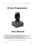
Thank you for purchasing BlinkRC! BlinkRC is a RC vehicle WiFi receiver, that's not just a WiFi receiver.
You see, BlinkRC has an open messaging protocol for interfacing its three PWM outputs and two analog inputs.
That means, you can write your own code to control BlinkRC. Any scripting or programming language that supports UDP messaging will suffice!
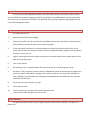
Quick Start
It’s as easy as B-G-1-2-3!
1.
Remove the board from the packaging.
2.
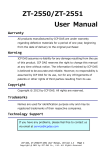
Take the cover off of your RC car. Remove all the PWM connectors from your Electronic Speed Control
(ESC). Generally, there will be either two or three connections.
3.
If one of the above connections is a dedicated power connection, plug that into the first slot on the
board, with the black wire facing the outside. If neither are dedicated power, plug the wire coming from
the motor into the first slot.
4.
Plug the remaining wires (motor and/or steering) into the second and third slots. Always make sure the
black wire faces the outside.
5.
Turn on your iPhone
6.
Go to Settings. Turn on Airplane Mode. This will prevent calls from interrupting your driving.
7.
Go to Wi-Fi. Find your device's wireless network-- BlinkGearXX, where XX represent the two digits at the
end of your device's MAC address. Configure the network to be Static. Give yourself an IP address between 192.168.1.2 ans 192.168.1.255, excluding 192.168.1.88 (the device's default IP). Give yourself a
Netmask of 255.255.255.0
8.
Exit to the main screen and start your app.
9.
You're ready to drive!
10.
If you're not driving, you might need to switch which channels
control throttle and steering on the second screen.
iPhone Controller
To obtain the iPhone controller, log into Apple's App Store and search for “BlinkRC”. The app is completely free.
Python Sample Code
The following Python code causes all PWM output channels to move to either extreme (-100 to 100) for
five iterations. It will simultaneously print out the incoming analog data from the board’s two analog inputs.
import sys, struct
from socket import *
#setup a listening UDP socket
udp_rx_sock = socket(AF_INET, SOCK_DGRAM)
udp_rx_sock.bind(('', 8088))
udp_rx_sock.settimeout(0.02) #20 ms timeout
#setup a transmit UDP socket
host = '192.168.1.88'
port = 8088
addr = (host, port)
udp_tx_sock = socket(AF_INET, SOCK_DGRAM)
udp_tx_sock.connect(addr)
#setup version number and send a servo command message (id = 0x40)
version = 0x01
msgId = 0x40
for runs in range(5):
for val in range(-100, 100):
#valid range for servo positions include [-100, 100] w/ 0 at center
ch1 = val
ch2 = val
ch3 = val
#pack the data into a string with the BG magic word header
data = 'BG%s' % struct.pack('>BBbbb', version, msgId, ch1, ch2, ch3)
#send the data
udp_tx_sock.sendto(data, addr)
#wait for a2d reply
try:
rxdata, addr = udp_rx_sock.recvfrom(16)
except:
pass
else:
print rxdata, addr, '\r',
Android Controller
Coming soon. Feel free to make your own and sell it in the Droid App Store!
Blackberry Controller
Coming soon. Feel free to make your own and sell it in Balckberry App World!
Messaging Protocol
The BlinkRC is controlled via UDP messages. Each message begins with the characters “BG” followed by
a single byte for the message version and a single byte for the message code. For example, the message code to
control the servos is 0x40 and it has three bytes of data. Since the character “B” is 66 in ASCII (0x42 in hexadecimal) and the character “G” is 71 in ASCII (0x47 in hexadecimal) and the message version is one, the first four
bytes of a servo control message would be 0x42 0x47 0x01 0x40. If the three bytes of data being sent in the
servo are 0x7 0x8 0x9, then the total servo control message would be 0x42 0x47 0x01 0x40 0x07 0x08 0x09.
The BlinkRC will respond to any valid BlinkGear message listed below with an Analog-to-Digital (ADC)
Message. The ADC Message follows the same format as the various control messages.
All messages are message version one unless otherwise stated.
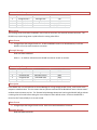
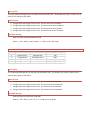
Servo Control Message
BYTES
2
1
1
1
1
1
TYPE
unsigned char*
unsigned char
unsigned char
char
char
char
Description
DESCRIPTION
message start
message version
command code
channel 1 percent
channel 2 percent
channel 3 percent
VALUE RANGE
"BG"
0x01
0x40
[-100:100]
[-100:100]
[-100:100]
This message controls the signal sent to the three servo control pins.
Data Format
a. Signed byte ranging from -100 to 100. Determines the effort of the servo or speed controller connected
to servo channel 1
b. Signed byte ranging from -100 to 100. Determines the effort of the servo or speed controller connected
to servo channel 2
c. Signed byte ranging from -100 to 100. Determines the effort of the servo or speed controller connected
o servo channel 3
Example Message
0x42 0x47 0x01 0x40 0xCE 0x00 0x32
where a = -50 = 0xCE, b = 0 = 0x00, and c = 50 = 0x32
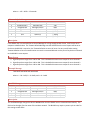
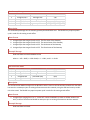
Analog-to-Digital Message
BYTES
2
1
1
1
1
1
TYPE
unsigned char*
unsigned char
unsigned char
unsigned char
unsigned char
unsigned char
DESCRIPTION
message start
message version
command code
channel 1 analog
channel 2 analog
temperature
VALUE RANGE
"BG"
0x01
0x06
[1:255]
[1:255]
[1:255]
Description
This is message gives the values of the analog-to-digital input pins. The BlinkRC sends this message in response
to any valid BlinkGear message it receives.
Data Format
a. Unsigned byte ranging from 1 to 255. Describes the voltage measured on ADC pin 1
b. Unsigned byte ranging from 1 to 255. Describes the voltage measured on ADC pin 2
c. Unsigned byte ranging from 1 to 255. Describes the voltage measured on the on-board microcontroller's internal temperature sensor.
Example Message
0x42 0x47 0x01 0x06 0x0A 0x14 0x28
where a = 10 = 0x0A, b = 20 = 0x14, and c = 40 = 0x28
Antenna Mode Message
BYTES
2
1
1
1
TYPE
unsigned char*
unsigned char
unsigned char
unsigned char
DESCRIPTION
message start
message version
command code
use external
VALUE RANGE
"BG"
0x01
0x0D
[0:1] (false:true)
Description
This message controls whether the BlinkRC uses its built in antenna or the external antenna connector. The
BlinkRC may require being power cycled before this setting takes effect.
Data Format
a. Unsigned byte that ranges from 0 to 1. 0 tells the BlinkRC to use its on-board antenna, 1 tells the
BlinkRC to use the external antenna connector.
Example Message
0x42 0x47 0x01 0x0D 0x00
where a = 0 = 0x00 to indicate that the BlinkRC should use its built-in antenna.
Timeout Delay Message
BYTES
2
1
1
1
TYPE
unsigned char*
unsigned char
unsigned char
unsigned char
DESCRIPTION
message start
message version
command code
50 per second delay
VALUE RANGE
"BG"
0x01
0x35
[0:250]
Description
If the BlinkRC has not received a Servo Control Message for a long enough period of time, it will set the servo
outputs to a default value. This is to ensure that any device connected to the BlinkRC will enter a known state if
wireless communications are lost. The Timeout Delay Message determines how long the BlinkRC will go without
receiving a Servo Control before setting the servo outputs to their default values. Each time the BlinkRC is
turned on the Timeout Delay is set to one second.
Data Format
a. Unsigned byte that ranges from 0 to 250. Each tick is two hundredths of a second.
Example Message
0x42 0x47 0x01 0x35 0x7D
where a = 125 = 0x7D = 2.5 seconds
Timeout Default Message
BYTES
2
1
1
1
1
1
TYPE
unsigned char*
unsigned char
unsigned char
char
char
char
DESCRIPTION
message start
message version
command code
channel 1
channel 2
channel 3
VALUE RANGE
"BG"
0x01
0x34
[-100:0]
[-100:0]
[-100:0]
Description
If the BlinkRC has not received a Servo Control Message for a long enough period of time, it will set the servo
outputs to a default value. The Timeout Default Message sets the defaults that the servo ouputs will be set to.
Each time the BlinkRC is turned on, the Timeout Defaults are set to all zeros. Be very careful when setting
Timeout Defaults as loss of communication can result in unwanted behavior on the part of any device connected
to the BlinkRC's servo outputs.
Data Format
a. Signed byte that ranges from -100 to 100. This is the default timeout servo output for servo channel 1
b. Signed byte that ranges from -100 to 100. This is the default timeout servo output for servo channel 2
c. Signed byte that ranges from -100 to 100. This is the default timeout servo output for servo channel 3
Example Message
0x42 0x47 0x01 0x34 0xEC 0x00 0x00
where a = -20 = 0xEC, b = 0 = 0x00, and c = 0 = 0x00
Set SSID Message
BYTES
2
1
1
32
TYPE
unsigned char*
unsigned char
unsigned char
unsigned char*
DESCRIPTION
message start
message version
command code
ssid
VALUE RANGE
"BG"
0x01
0x0E
[alphanumeric]
Description
The Set SSID Message changes the Service Set IDentifier that the BlinkRC uses to communicate wirelessly. The
SSID can be thought of as the name of the wireless network. The BlinkRC may require a power cycle in order for
this setting to take effect.
Data Format
a. 32 single-byte character string that is the new SSID. All 32 bytes must be sent. Unused bytes should be
set to zero.
Example Message
0x42 0x47 0x01 0x0E 0x42 0x6C 0x69 0x6E 0x47 0x65 0x61 0x72 0x00 0x00 0x00 0x00 0x00 0x00 0x00
0x00 0x00 0x00 0x00 0x00 0x00 0x00 0x00 0x00 0x00 0x00 0x00 0x00 0x00 0x00 0x00
where a = “BlinkGear” = 0x42 0x6C 0x69 0x6E 0x47 0x65 0x61 0x72 and the remaining 23 bytes are 0x00
Set Network Key Message
BYTES
2
1
1
32
TYPE
unsigned char*
unsigned char
unsigned char
unsigned char*
DESCRIPTION
message start
message version
command code
network key
VALUE RANGE
"BG"
0x01
0x0F
[alphanumeric]
Description
The Set Network Key Message sets the security key or pass-phrase that the BlinkRC uses to connect to secured
wireless networks. The BlinkRC is able to connect to networks that use 128-bit WEP encryption or WPA or
WPA2 encryption. The BlinkRC may require a power cycle in order for this setting to take effect.
Data Format
a. 32 single-byte character string that is the key or pass-phrase. All 32 bytes must be sent. Unused bytes
should be set to zero.
Example Message
0x42 0x47 0x01 0x0F 0x70 0x61 0x73 0x73 0x70 0x68 0x72 0x61 0x73 0x65 0x00 0x00 0x00 0x00 0x00
0x00 0x00 0x00 0x00 0x00 0x00 0x00 0x00 0x00 0x00 0x00 0x00 0x00 0x00 0x00 0x00 0x00
where a = “passphrase” = 0x70 0x61 0x73 0x73 0x70 0x68 0x72 0x61 0x73 0x65 and the remaining 22
bytes are 0x00
Set IP Address Message
BYTES
2
1
1
4
TYPE
unsigned char*
unsigned char
unsigned char
unsigned char*
DESCRIPTION
message start
message version
command code
ip address
VALUE RANGE
"BG"
0x01
0x10
[1:255][1:255][1:255][1:255]
Description
The Set IP Address Message sets the IP address that the BlinkRC uses. The BlinkRC may require a power cycle in
order for this setting to take effect.
Data Format
a.
b.
c.
d.
Unsigned byte that ranges from 0 to 255.
Unsigned byte that ranges from 0 to 255.
Unsigned byte that ranges from 0 to 255.
Unsigned byte that ranges from 0 to 255.
The first octet of the IP address.
The second octet of the IP address.
The third octet of the IP address.
The fourth octet of the IP address.
Example Message
0x42 0x47 0x01 0x10 0xC0 0xA8 0x01 0x58
where a = 192 = 0xC0, b = 168 = 0xA8, c = 1 = 0x01, and d = 88 = 0x58
Set Netmask Message
BYTES
2
1
1
4
TYPE
unsigned char*
unsigned char
unsigned char
unsigned char*
DESCRIPTION
message start
message version
command code
netmask address
VALUE RANGE
"BG"
0x01
0x11
[1:255][1:255][1:255][1:255]
Description
The Set Netmask Message sets the netmask that the BlinkRC uses. The BlinkRC may require a power cycle in
order for this setting to take effect.
Data Format
a.
b.
c.
d.
Unsigned byte that ranges from 0 to 255.
Unsigned byte that ranges from 0 to 255.
Unsigned byte that ranges from 0 to 255.
Unsigned byte that ranges from 0 to 255.
The first octet of the Netmask
The second octet of the Netmask
The third octet of the Netmask
The fourth octet of the Netmask
Example Message
0x42 0x47 0x01 0x11 0xFF 0xFF 0x00 0x00
where a = 255 = 0xFF, b = 255 = FF, c = 0 = 0x00, and d = 0 = 0x00
Set Gateway Message
BYTES
2
1
1
4
TYPE
unsigned char*
unsigned char
unsigned char
unsigned char*
DESCRIPTION
message start
message version
command code
gateway address
VALUE RANGE
"BG"
0x01
0x12
[1:255][1:255][1:255][1:255]
Description
The Set Gateway Message sets the network gateway that the BlinkRC uses. The BlinkRC may require a power
cycle in order for this setting to take effect.
Data Format
a.
b.
c.
d.
Unsigned byte that ranges from 0 to 255.
Unsigned byte that ranges from 0 to 255.
Unsigned byte that ranges from 0 to 255.
Unsigned byte that ranges from 0 to 255.
The first octet of the Gateway
The second octet of the Gateway
The third octet of the Gateway
The fourth octet of the Gateway
Example Message
0x42 0x47 0x01 0x12 0xC0 0xA8 0x01 0x01
where a = 192 = 0xC0, b = 168 = 0xA8, c = 1 = 0x01, and d = 1 = 0x01
Set Connection Mode
BYTES
2
1
1
1
TYPE
unsigned char*
unsigned char
unsigned char
unsigned char
DESCRIPTION
message start
message version
command code
infrastructure/adhoc
VALUE RANGE
"BG"
0x01
0x13
[0:1]
Description
The Set Connection Mode message tells the BlinkRC to either create an Ad-Hoc wireless network with the SSID it
has saved or to attempt to join an existing Infrastructure wireless network, using the SSID and security credentials it has saved. The BlinkRC may require a power cycle in order for this setting to take effect.
Data Format
a. Unsigned byte ranging from 0 to 1. A value of 1 causes the BlinkRC to create an Ad-Hoc wireless network, a value of 0 causes the BlinkRC to attempt to join an existing Infrastructure wireless network.
Example Message
0x42 0x47 0x01 0x13 0x01
where a = 1, indicating that the BlinkRC should create its own Ad-Hoc wireless network
Network Reset Message
BYTES
2
1
1
TYPE
unsigned char*
unsigned char
unsigned char
DESCRIPTION
message start
message version
command code
VALUE RANGE
"BG"
0x01
0x0C
Description
The Network Reset Message causes the BlinkRC to power cycle its onboard wifi module.
Data Format
None
Example Message
0x42 0x47 0x01 0x0C
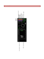
Hardware Reset
You can apply a hardware reset by shorting the reset jumper contacts together before applying power.
Then keeping them shorted, apply power to the BlinkRC board and the LED will slowly flash red as it performs
the necessary operations. After approximately 6 seconds, the LED will turn green and all settings including WiFi
SSID will be reset to the factory defaults.
Hardware Specification