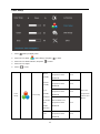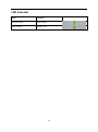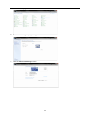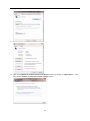
1
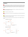
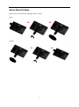
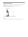
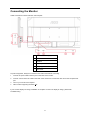
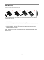
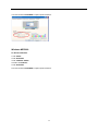
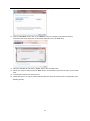
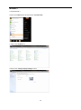
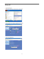
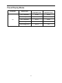
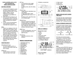
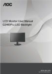
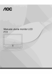
s
Safety........................................................................................................................................................................ 3
National Conventions......................................................................................................................................... 3
Power ................................................................................................................................................................ 4
Installation ......................................................................................................................................................... 5
Cleaning ............................................................................................................................................................ 6
Other.................................................................................................................................................................. 7
Setup ........................................................................................................................................................................ 8
Contents of the Box ........................................................................................................................................... 8
Setup Stand & Base .......................................................................................................................................... 9
Adjusting Viewing Angle .................................................................................................................................. 10
Connecting the Monitor.................................................................................................................................... 11
System requirement......................................................................................................................................... 12
Wall Mounting .................................................................................................................................................. 13
Adjusting ................................................................................................................................................................. 14
Setting Optimal Resolution .............................................................................................................................. 14
Windows Vista .......................................................................................................................................... 14
Windows XP ............................................................................................................................................. 16
Windows ME/2000 .................................................................................................................................... 17
Windows 8 ................................................................................................................................................ 18
Hotkeys............................................................................................................................................................ 20
OSD Setting..................................................................................................................................................... 21
Luminance (3D function disable) .............................................................................................................. 22
Luminance (3D function enable) ............................................................................................................... 22
Color Setup............................................................................................................................................... 24
OSD Setup ............................................................................................................................................... 26
Extra ......................................................................................................................................................... 28
LED Indicator ................................................................................................................................................... 30
Driver ...................................................................................................................................................................... 31
Monitor Driver .................................................................................................................................................. 31
Windows 8 ................................................................................................................................................ 31
Windows 7 ................................................................................................................................................ 35
Windows Vista .......................................................................................................................................... 39
Windows XP ............................................................................................................................................. 41
Windows 2000 .......................................................................................................................................... 44
Windows ME ............................................................................................................................................. 44
Troubleshoot ........................................................................................................................................................... 45
Specification............................................................................................................................................................ 46
General Specification....................................................................................................................................... 46
Preset Display Modes ...................................................................................................................................... 47
Plug and Play .................................................................................................................................................. 49
Regulation............................................................................................................................................................... 50
FCC Notice ...................................................................................................................................................... 50
WEEE Declaration ........................................................................................................................................... 51
Service .................................................................................................................................................................... 52
EU WARRANTY FOR AOC MONITORS ......................................................................................................... 52
Warranty Statement for North & South America (excluding Brazil) ........................................................... 54
2
Safety
National Conventions
The following subsections describe notational conventions used in this document.
Notes, Cautions, and Warnings
Throughout this guide, blocks of text may be accompanied by an icon and printed in bold type or in italic type.
These blocks are notes, cautions, and warnings, and they are used as follows:
NOTE: A NOTE indicates important information that helps you make better use of your computer system.
CAUTION: A CAUTION indicates either potential damage to hardware or loss of data and tells you how to avoid the
problem.
WARNING: A WARNING indicates the potential for bodily harm and tells you how to avoid the problem. Some
warnings may appear in alternate formats and may be unaccompanied by an icon. In such cases, the specific
presentation of the warning is mandated by regulatory authority.
3
Power
The monitor should be operated only from the type of power source indicated on the label. If you are not sure
of the type of power supplied to your home, consult your dealer or local power company.
The monitor is equipped with a three-pronged grounded plug, a plug with a third (grounding) pin. This plug
will fit only into a grounded power outlet as a safety feature. If your outlet does not accommodate the three-wire
plug, have an electrician install the correct outlet, or use an adapter to ground the appliance safely. Do not defeat
the safety purpose of the grounded plug.
Unplug the unit during a lightning storm or when it will not be used for long periods of time. This will protect
the monitor from damage due to power surges.
Do not overload power strips and extension cords. Overloading can result in fire or electric shock.
To ensure satisfactory operation, use the monitor only with UL listed computers which have appropriate
configured receptacles marked between 100 - 240V ~, Min. 5A
The wall socket shall be installed near the equipment and shall be easily accessible.
For use only with the attached power adapter (input:100-240V~, 50/60Hz Output 19Vdc,3.42A) which have
UL,CSA, cTUVus listed license (Only for monitors with power adapter).
Manufacturer:
TPV ELECTRONICS(FUJIAN) CO., LTD Model : ADPC1965
4
Installation
Do not place the monitor on an unstable cart, stand, tripod, bracket, or table. If the monitor falls, it can injure a
person and cause serious damage to this product. Use only a cart, stand, tripod, bracket, or table recommended by
the manufacturer or sold with this product. Follow the manufacturer’s instructions when installing the product and
use mounting accessories recommended by the manufacturer. A product and cart combination should be moved
with care.
Never push any object into the slot on the monitor cabinet. It could damage circuit parts causing a fire or
electric shock. Never spill liquids on the monitor.
Do not place the front of the product on the floor.
If you mount the monitor on a wall or shelf, use a mounting kit approved by the manufacturer and follow the kit
instructions.
Leave some space around the monitor as shown below. Otherwise, air-circulation may be inadequate hence
overheating may cause a fire or damage to the monitor.
See below the recommended ventilation areas around the monitor when the monitor is installed on the wall or on
the stand:
5
Cleaning
Clean the cabinet regularly with cloth.
You can use soft-detergent to wipe out the stain, instead of
strong-detergent which will cauterize the product cabinet.
When cleaning, make sure no detergent is leaked into the product. The cleaning cloth should not be too
rough as it will scratch the screen surface.
Please disconnect the power cord before cleaning the product.
6
Other
If the product is emitting a strange smell, sound or smoke, disconnect the power plug IMMEDIATELY and
contact a Service Center.
Make sure that the ventilating openings are not blocked by a table or curtain.
Do not engage the LCD monitor in severe vibration or high impact conditions during operation.
Do not knock or drop the monitor during operation or transportation.
7
Setup
Contents of the Box
Monitor
CD Manual
Power Cable
USB Cable
Stand
Wire holder
DP
Not all signal cables (Audio,Analog, DVI, DP, USB and HDMI cables) will be provided for all countries and
regions. Please check with the local dealer or AOC branch office for confirmation.
8
Setup Stand & Base
Please setup or remove the base following the steps as below.
Setup:
Remove:
9
Adjusting Viewing Angle
For optimal viewing it is recommended to look at the full face of the monitor, then adjust the monitor's angle to your
own preference.
Hold the stand so you will not topple the monitor when you change the monitor's angle.
You are able to adjust the monitor's angle from -5° to 20 °.
NOTE:
Do not touch the LCD screen when you change the angle. It may cause damage or break the LCD screen.
10
Connecting the Monitor
Cable Connections In Back of Monitor and Computer:
1
USB2.0 + fast charging
2
USB2.0
3
USB3.0
4
USB input
5
Display port
6
DC Power
To protect equipment, always turn off the PC and LCD monitor before connecting.
1
Connect the power cable to the AC port on the back of the monitor.
2
Connect one end of the DP cable to the back of the monitor and connect the other end to the computer’s DP
port.
3
Turn on your monitor and computer.
4
Video content supporting resolution: DP.
If your monitor displays an image, installation is complete. If it does not display an image, please refer
Troubleshooting.
11
System requirement
1. G-system function:
Compatible Graphics Card: GeForce GTX 650 Ti Boost or higher (for a list of compatible graphics cards, please
visit www.nvidia.com/G-sync)
Driver: GeForce 331.58 or higer
OS: Windows 7/8/8.1
2. 3D function:
The G-Sync monitor is NVIDIA 3D Vision Ready monitor. To enable 3D function, NVIDIA 3D version kit is required.
NVIDIA 3D version kit requirement for stereoscopic 3D experience for a list of compatible graphics cards, please
visit www.nvidia.com/3DVisionG-sync
12
Wall Mounting
Preparing to Install An Optional Wall Mounting Arm.
This monitor can be attached to a wall mounting arm you purchase separately. Disconnect power before this
procedure. Follow these steps:
1
Remove the base.
2
Follow the manufacturer's instructions to assemble the wall mounting arm.
3
Place the wall mounting arm onto the back of the monitor. Line up the holes of the arm with the holes in the
back of the monitor.
4
Insert the 4 screws into the holes and tighten.
5
Reconnect the cables.
Refer to the user's manual that came with the optional wall mounting arm for
instructions on attaching it to the wall.
Noted :
VESA mounting screw holes are not available for all models, please check with the dealer or official
department of AOC.
13
Adjusting
Setting Optimal Resolution
Windows Vista
For Windows Vista:
1 Click START.
2 Click CONTROL PANEL.
3 Click Appearance and Personalization.
4 Click Personalization
14
5 Click Display Settings.
6 Set the resolution SLIDE-BAR to Optimal preset resolution.
15
Windows XP
For Windows XP:
1 Click START.
2 Click SETTINGS.
3 Click CONTROL PANEL.
4 Click Appearance and Themes.
5 Double click DISPLAY.
16
6 Click SETTINGS.
7 Set the resolution SLIDE-BAR to Optimal preset resolution.
Windows ME/2000
For Windows ME/2000:
1 Click START.
2 Click SETTINGS.
3 Click CONTROL PANEL.
4 Double click DISPLAY.
5 Click SETTINGS.
6 Set the resolution SLIDE-BAR to Optimal preset resolution.
17
Windows 8
For Windows 8:
1.
Right click and click All apps at the bottom-right of the screen.
2.
Set the “View by” to “Category”.
3.
Click Appearance and Personalization.
18
4.
Click DISPLAY.
5.
Set the resolution SLIDE-BAR to 1920x1080.
19
Hotkeys
1
(Dialpoint OFF\ON) / Exit
2
Dialpoint selection menu / <
3
ULMB / >
4
Menu / Enter
5
Power
(Dialpoint Off\On) / Exit
When the OSD is closed, press (Dialpoint OFF\ON) button will be on or off Dialpoint type. When the OSD is not
closed,press Exit button to save user data.
< Dialpoint Selection Menu
Press the Dialpoint selection menu key to active the Dialpoint menu . Press < or > button to choose a different
Frosshair type.
> ULMB (Ultra Low Motion Blur)
When there is no OSD, Press ULMB button to active ULMB off/on bar, Press < or > button to active ULMB mode .
NVIDIA ULMB is a technology that eliminates virtually all motion blur associated with LCD displays. When playing a
game using ULMB, moving images will be perfectly sharp, without the blurring seen on a traditional LCD monitor.
ULMB can be a big advantage in gaming. In First Person Shooters you can spot an enemy faster. In top view
scrolling games, you can read text without stopping to identify a treasure. Try ULMB on your game whenever you
have a high FPS, for amazing results.
Menu/Enter
Press to display the OSD or confirm the selection.
Power
Press the Power button, the monitor will go into standby mode. After 12minutes, the monitor will turn off
automatically.
20
OSD Setting
Basic and simple instruction on the control keys.
MENU-button to activate the OSD window.
1)
Press the
2)
Press < or > to navigate through the functions. Once the desired function is highlighted, press the
MENU-button to activate it . press < or > to navigate through the sub-menu functions. Once the desired
function is highlighted, press
3)
MENU-button to activate it.
Press < or > to change the settings of the selected function. Press
any other function, repeat steps 2-3.
21
AUTO to exit.
If you want to adjust
Luminance (3D function disable)
Luminance (3D function enable)
Contrast
@
NVIDIA LightBoost
Gamma
Luminance
50
Color Setup
tm
Gamma 1
OSD Setup
Off
Extra
Overdrive
1.
Press
(Menu) to display menu.
2.
Press < or > to select
3.
4.
Press < or > to select submenu, and press
Press < or > to adjust.
5.
Press
(Luminance), and press
to enter.
to exit.
22
to enter.
Backlight
Adjustment
Brightness
Each step will
increase /
Recall
0-100
Brightness
Value 90
decrease value
by 1
Contrast from
Recall
Digital-register.
Luminance
Each step will
Contrast
increase /
0-100
decrease value
Contrast
by 1
Value 50
Gamma
Overdrive
Gamma
Gamma1 (2.2)
Adjustment
Gamma2 (2.0)
Recall
Gamma3 (2.4)
Gamma1
Value
adjust the
response time
Strong/Medium/Light/Weak/Off
Note: When the 3D function starts brightness options are replaced by NVIDIA Light Boost options. default
value is 90. The maximum value show “MAX”,the minimum value
bar.
23
show “OFF”. There is not number
Color Setup
1.
Press
(Menu) to display menu.
2.
Press < or > to select
3.
Press < or > to select submenu, and press
4.
Press < or > to adjust.
5.
Press
to enter.
to exit.
Recall Warm Color
Warm
Temperature from
(6500K)
Recall Normal Color
Temperature from
(7300K)
Setup
N/A
EEPROM.
Recall Cool Color
Cool
Color Temp
N/A
EEPROM.
Normal
Color
to enter.
(Color Setup), and press
Temperature from
(9300K)
N/A
EEPROM.
Recall sRGB Color
with
Temperature from
sRGB
EEPROM.
Warm.
N/A
function)
Recall User Color
User
Temperature from
EEPROM.
24
Temperature
will be set to
sRGB(for
the model
The Color
N/A
Red gain from
Red
Digital-register.
N/A
Each step will increase
0-100
R/G/B
/ decrease value by 1
Green
N/A
Green gain from
0-100
Digital-register.
reset
Blue gain from
N/A
Each step will increase
/ decrease value by 1
Note: (1) In the sRGB color temperature, brightness, contrast is not adjustable
(2)
OSD menu color will change with the picture color change
25
is 50) will
modified by
/ decrease value by 1
Blue
value(default
not be
Each step will increase
Digital-register.
The User
function in
0-100
user mode.
OSD Setup
1.
Press
(Menu) to display menu.
2.
Press < or > to select
3.
4.
Press < or > to select submenu, and press
Press < or > to adjust.
5.
Press
(OSD Setup), and press
to enter.
to enter.
to exit.
English
Français
Español
Português
Deutsch
Italiano
OSD
Setup
Language
No need
to recall
language
while
press
“RESET”.
Set OSD display
Nederlands
language to English.
Svenska
If
(English is default
Suomi
customer
setting)
Polski
have
Čeština
different
Русский
request,
한국어
please
繁体中文
refer to
简体中文
日本语
26
customer
request
Adjust the OSD
timeout.
Timeout
Each step will increase /
5-120
Recall 10
Value
decrease value by 5
Adjust the horizontal
H. Position
position of the OSD.
Each step will increase /
0-100
Recall
100 Value
decrease value by 25
Adjust the vertical
V. Position
position of the OSD.
Each step will increase /
0-100
Recall 0
Value
decrease value by 5
Adjust the OSD
Transparence
transparent each step
will increase/decrease
Recall 25
0-100
Value
value by 25
Break
Reminder
Break Reminder if the
user continuely work
for mare than 1 hurs
Recall
ON/OFF
OFF
Value
Note:
1) If turn on, a time break reminder message is generated for each hour (1, 2, 3 ……24 hours, > 24 hours), the
message will be showed for 10 sec. Also, the message will disappear when press any function key.
2)The message location is at the default screen center position and cannot change via OSD.
3)When power on/off, DC on/off, or enter/exit power saving mode, the working time is to clear and recalculate.
4)OSD time out can save data.
27
Extra
1.
Press
(Menu) to display menu.
2.
Press < or > to select
3.
Press < or > to select submenu, and press
4.
Press < or > to adjust.
5.
Press
(Extra), and press
to enter.
to enter.
to exit.
28
Clear each old status of
Auto-configuration and
set the color temperature
YES
to Warm
N/A
Reset
Do not execute reset,
return to main menu.
Extra
G_sync
NO
function
disable and timing V
freq >=85hz
On
Off
ULMB
G_sync
function
enable or display card
do not support G_sync
Off
function
Note :
1)
2)
The OSD language is not be reseted.
ULMB mode cannot be adjusted when G_sync function enable or display card do not support G_sync
function.
29
LED Indicator
Status
LED Color
Full Power Mode
Green or Blue
Active-off Mode
Orange or red
30
Driver
Monitor Driver
Windows 8
1.
Start Windows® 8
2.
Right click and click All apps at the bottom-right of the screen.
3.
Click on the “Control panel” icon
4.
Set the “View by” to “Large icons” or “Small icons”.
31
5.
Click on the “Display” icon.
6.
Click on the “Change display settings” button.
7.
Click the “Advanced Settings” button.
32
8.
Click the “Monitor” tab and then click the “Properties” button.
9.
Click the “Driver” tab.
10. Open the “Update Driver Software-Generic PnP Monitor” window by clicking on “Update Driver... “ and
then click the "Browse my computer for driver software" button.
33
11. Select "Let me pick from a list of device drivers on my computer".
12. Click the “Have Disk” button. Click on the “Browse” button and navigate to the following directory:
X:\Driver\module name (where X is the drive letter designator for the CD-ROM drive).
13. Select the "xxx.inf" file and click the “Open” button. Click the “OK” button.
14. Select your monitor model and click the “Next” button. The files will be copied from the CD to your hard disk
drive.
15. Close all open windows and remove the CD.
16. Restart the system. The system will automatically select the maximum refresh rate and corresponding Color
Matching Profiles.
34
Windows 7
1.Start Windows® 7
2.Click on the 'Start' button and then click on 'Control Panel'.
3. Click on the 'Display' icon.
4.Ckick on the “Change display settings” button.
35
5.Click the “Advanced Settings” button.
6.Click the “Monitor” tab and then click the “Properties” button.
7.Click the “Driver” tab.
36
8. Open the "Update Driver Software-Generic PnP Monitor" window by clicking on “Update Driver... “and then
click the "Browse my computer for driver software" button.
9. Select "Let me pick from a list of device drivers on my computer".
10. Click the “Have Disk” button. Click on the “Browse” button and navigate to the following directory:
X:\Driver\module name
(where X is the drive letter designator for the CD-ROM drive).
37
11. Select the "xxx.inf" file and click the “Open” button. Click the “OK” button.
12. Select your monitor model and click the “Next” button. The files will be copied from the CD to your hard disk
drive.
13. Close all open windows and remove the CD.
14. Restart the system. The system will automatically select the maximum refresh rate and corresponding Color
Matching Profiles.
38
Windows Vista
1. Click "Start " and "Control Panel". Then, double-click on "Appearance and Personalization".
2. Click "Personalization" and then "Display Settings".
3. Click "Advanced Settings...".
39
4. Click "Properties" in the "Monitor" tab. If the "Properties" button is deactivated, it means the configuration for your
monitor is completed. The monitor can be used as is.
If the message "Windows needs..." is displayed, as shown in the figure below, click "Continue".
5. Click "Update Driver..." in the "Driver" tab.
6. Check the "Browse my computer for driver software" checkbox and click "Let me pick from a list of device drivers
on my computer".
7. Click on the 'Have disk...' button, then click on the 'Browse...' button and then select the appropriate drive
F:\Driver (CD-ROM Drive).
8. Select your monitor model and click on the 'Next' button.
9. Click "Close" → "Close" → "OK" → "OK" on the following screens displayed in sequence.
40
Windows XP
1. Start Windows® XP
2. Click on the 'Start' button and then click on 'Control Panel'.
3. Select and click on the category ‘Appearance and Themes’
4. Click on the 'Display' Item.
41
5. Select the 'Settings' tab then click on the 'Advanced' button.
6. Select 'Monitor' tab
- If the 'Properties' button is inactive, it means your monitor is properly configured. Please stop installation.
- If the 'Properties' button is active, click on 'Properties' button.
Please follow the steps below.
7. Click on the 'Driver' tab and then click on 'Update Driver...' button.
42
8. Select the 'Install from a list or specific location [advanced]' radio button and then click on the 'Next' button.
9. Select the 'Don't Search. I will choose the driver to install' radio button. Then click on the 'Next' button.
10. Click on the 'Have disk...' button, then click on the 'Browse...' button and then select the appropriate drive F:
(CD-ROM Drive).
11. Click on the 'Open' button, then click the 'OK' button.
12. Select your monitor model and click on the 'Next' button.
- If you can see the 'has not passed Windows® Logo testing to verify its compatibility with Windows® XP' message,
please click on the 'Continue Anyway' button.
13. Click on the 'Finish' button then the 'Close' button.
14. Click on the 'OK' button and then the 'OK' button again to close the Display Properties dialog box.
43
Windows 2000
1. Start Windows® 2000
2. Click on the 'Start' button, point to 'Settings', and then click on 'Control Panel'.
3. Double click on the 'Display' Icon.
4. Select the 'Settings' tab then click on 'Advanced...'.
5. Select 'Monitor'
- If the 'Properties' button is inactive, it means your monitor is properly configured. Please stop installation.
- If the 'Properties' button is active. Click on 'Properties' button. Please follow the steps given below.
6. Click on 'Driver' and then click on 'Update Driver...' then click on the 'Next' button.
7. Select 'Display a list of the known drivers for this device so that I can choose a specific driver', then click on 'Next'
and then click on 'Have disk...'.
8. Click on the 'Browse...' button then select the appropriate drive F: ( CD-ROM Drive).
9. Click on the 'Open' button, then click on the 'OK' button.
10. Select your monitor model and click on the 'Next' button.
11. Click on the 'Finish' button then the 'Close' button.
If you can see the 'Digital Signature Not Found' window, click on the 'Yes' button.
Windows ME
1. Start Windows® Me
2. Click on the 'Start' button, point to 'Settings', and then click on 'Control Panel'.
3. Double click on the 'Display' Icon.
4. Select the 'Settings' tab then click on 'Advanced...'.
5. Select the 'Monitor' button, then click on 'Change...' button.
6. Select 'Specify the location of the driver(Advanced)' and click on the 'Next' button.
7. Select 'Display a list of all the drivers in a specific location, so you can choose the driver you want', then click on
'Next' and then click on 'Have Disk...'.
8. Click on the 'Browse...' button, select the appropriate drive F: ( CD-ROM Drive) then click on the 'OK' button.
9. Click on the 'OK' button, select your monitor model and click on the 'Next' button.
10. Click on 'Finish' button then the 'Close' button.
44
Troubleshoot
Problem & Question
Possible Solutions
Power LED Is Not ON
Make sure the power button is ON and the Power Cord is properly connected
to a grounded power outlet and to the monitor.
Is the power cord connected properly?
Check the power cord connection and power supply.
Is the cable connected correctly?
(Connected using the DP cable)
No images on the screen
If the power is on, reboot the computer to see the initial screen (the login
screen), which can be seen.
If the initial screen (the login screen) appears, boot the computer in the
applicable mode (the safe mode for Windows ME/XP/2000) and then change
the frequency of the video card.
(Refer to the Setting the Optimal Resolution)
If the initial screen (the login screen) does not appear, contact the Service
Center or your dealer.
Can you see "Input Not Supported" on the screen?
You can see this message when the signal from the video card exceeds the
maximum resolution and frequency that the monitor can handle properly.
Adjust the maximum resolution and frequency that the monitor can handle
properly.
Make sure the AOC Monitor Drivers are installed.
Picture Is Fuzzy & Has
Ghosting Shadowing Problem
Adjust the Contrast and Brightness Controls.
Press to auto adjust.
Make sure you are not using an extension cable or switch box. We
recommend plugging the monitor directly to the video card output connector
on the back .
Picture Bounces, Flickers Or
Wave Pattern Appears In The
Picture
Move electrical devices that may cause electrical interference as far away
from the monitor as possible.
Use the maximum refresh rate your monitor is capable of at the resolution
your are using.
Monitor Is Stuck In Active
Off-Mode"
The Computer Power Switch should be in the ON position.
The Computer Video Card should be snugly fitted in its slot.
Make sure the monitor's video cable is properly connected to the computer.
Inspect the monitor's video cable and make sure no pin is bent.
Make sure your computer is operational by hitting the CAPS LOCK key on
the keyboard while observing the CAPS LOCK LED. The LED should either
turn ON or OFF after hitting the CAPS LOCK key.
Missing one of the primary
colors (RED, GREEN, or
BLUE)
Inspect the monitor's video cable and make sure that no pin is damaged.
Make sure the monitor's video cable is properly connected to the computer.
Picture has color defects
(white does not look white)
Adjust RGB color or select desired color temperature.
45
Specification
General Specification
Panel
Model name
G2460PG
Driving system
TFT Color LCD
Viewable Image Size
61.0 cm diagonal
Pixel pitch
0. 27675 mm(H) x 0. 27675 mm(V)
Video
DP Interface
Separate Sync.
H/V TTL
Display Color
16.7M Colors
Dot Clock
325.08MHz
Horizontal scan range
30kHz~160kHz
Horizontal scan Size(Maximum) 531.36 mm
Resolution
Vertical scan range
30Hz~150Hz
Vertical scan Size(Maximum)
298.89 mm
Optimal preset resolution
1920 x 1080 (144Hz)
Plug & Play
VESA DDC2B™
Input Connector
DP
Input Video Signal
DP
Output Connector
NA
Power Source
19Vdc,3.42A
Active 33 W (typical)
Power Consumption
Standby < 0.5 W (after 15 minutes of no signal monitor will
go into standby mode)
Physical
Characteristics
Off timer
0~24 hrs
Speakers
NA
Connector Type
Signal Cable Type
Temperature
Environmental
Humidity
DP
Detachable
Operating
0° to 40°
Non-Operating
-25°to 55°
Operating
10% to 85% (non-condensing)
Non-Operating
5% to 93% (non-condensing)
46
Preset Display Modes
STANDARD
HD
HORIZONTAL
VERTICAL
FREQUENCY(kHZ)
FREQUENCY(Hz)
1920×1080@60Hz
67.500
60.000
1920×1080@100Hz
113.300
100
1920×1080@85Hz
96.513
84.884
1920×1080@120Hz
137.260
119.982
1920×1080@144Hz
158.110
144
RESOLUTION
47
20-Pin Color Display Signal Cable
Pin No.
Signal Name
Pin No.
1
ML_Lane 3 (n)
11
GND
2
GND
12
ML_Lane 0 (p)
3
ML_Lane 3 (p)
13
CONFIG1
4
ML_Lane 2 (n)
14
CONFIG2
5
GND
15
AUX_CH(p)
6
ML_Lane 2 (p)
16
GND
7
ML_Lane 1 (n)
17
AUX_CH(n)
8
GND
18
Hot Plug Detect
9
ML_Lane 1 (p)
19
Return DP_PWR
10
ML_Lane 0 (n)
20
DP_PWR
48
Signal Name
Plug and Play
Plug & Play DDC2B Feature
This monitor is equipped with VESA DDC2B capabilities according to the VESA DDC STANDARD. It allows the
monitor to inform the host system of its identity and, depending on the level of DDC used, communicate additional
information about its display capabilities.
49
Regulation
FCC Notice
FCC Class B Radio Frequency Interference Statement WARNING: (FOR FCC CERTIFIED MODELS)
NOTE: This equipment has been tested and found to comply with the limits for a Class B digital device, pursuant to
Part 15 of the FCC Rules. These limits are designed to provide reasonable protection against harmful interference
in a residential installation. This equipment generates, uses and can radiate radio frequency energy, and if not
installed and used in accordance with the instructions, may cause harmful interference to radio communications.
However, there is no guarantee that interference will not occur in a particular installation. If this equipment does
cause harmful interference to radio or television reception, which can be determined by turning the equipment off
and on, the user is encouraged to try to correct the interference by one or more of the following measures:
Reorient or relocate the receiving antenna.
Increase the separation between the equipment and receiver.
Connect the equipment into an outlet on a circuit different from that to which the receiver is connected.
Consult the dealer or an experienced radio/TV technician for help.
NOTICE :
The changes or modifications not expressly approved by the party responsible for compliance could void the user's
authority to operate the equipment.
Shielded interface cables and AC power cord, if any, must be used in order to comply with the emission limits.
The manufacturer is not responsible for any radio or TV interference caused by unauthorized modification to this
equipment. It is the responsibilities of the user to correct such interference. It is the responsibility of the user to
correct such interference.
50
WEEE Declaration
Disposal of Waste Equipment by Users in Private Household in the European Union.
This symbol on the product or on its packaging indicates that this product must not be disposed of with your other
household waste.Instead, it is your responsibility to dispose of your waste equipment by handing it over to a
designated collection point for the recycling of waste electrical and electronic equipment.The separate collection
and recycling of your waste equipment at the time of disposal will help to conserve natural resources and ensure
that it is recycled in a manner that protects human health and the environment. For more information about where
you can drop off your waste equipment for recycling, please contact your local city office, your household waste
disposal service or the shop where you purchased the product .
This symbol on the product or on its packaging indicates that this product must not be disposed of with your other
household waste. Instead it is your responsibility to dispose of your waste equipment by handing it over to a
designated collection point for the recycling of waste electrical and electronic equipment. The separate collection
and recycling of your waste equipment at the time of disposal will help to conserve natural resources and ensure
that it is recycled in a manner that protects human health and the environment.
For more information about where you can drop off your waste equipment for recycling in India please visit the
below web link.
www.aocindia.com/ewaste.php.
51
Service
EU WARRANTY FOR AOC MONITORS
LIMITED THREE-YEAR WARRANTY*
For AOC LCD Monitors sold within Europe, AOC International (Europe) B.V. warrants this product to be free from
defects in material and workmanship for a period of Three (3) years after the original date of consumer purchase.
During this period, AOC International (Europe) B.V. will, at its option, either repair the defective product with new or
rebuilt parts, or replace it with a new or rebuilt product at no charge except as *stated below. In the absent of the
proof of purchase, the warranty will start 3 months after the date of manufacturing indicated on the product.
If the product appears to be defective, please contact your local dealer or refer to the service and support section
on www.aoc-europe.com for warranty instructions. Deliver the product freight pre-paid, along with the dated proof
of purchase, to the AOC Certified or Authorized Service Center under the following condition:
•
Make sure the LCD Monitor is packed in a proper carton box (AOC prefers the original carton box to
protects your monitor well enough during transport).
•
Put the RMA number on the address label
•
Put the RMA number on the shipping carton
AOC International (Europe) B.V. is not responsible for any damaged during transport due to improper packing. AOC
International (Europe) B.V. will pay the return shipping charges within one of the countries specified within this
warranty statement. AOC International (Europe) B.V. is not responsible for any costs associated with the
transportation of product across international borders. This includes the international border within the European
Union. If the LCD Monitor is not available for collection when the currier attends, you will be charged a collection
fee.
* This limited warranty does not cover any losses or damages that occur as a result of: •
Improper installation or maintenance
•
Misuse
•
Neglect
•
Any cause other than ordinary commercial or industrial application
•
Adjustment by non-authorized source
•
Repair, modification, or installation of options or parts by anyone other than an AOC Certified or
Authorized Service Center
•
Improper environments like humidity and dusts
•
Damaged by violence
•
Excessive or inadequate heating or air conditioning or electrical powers failures, surges, or other
irregularities
52
All AOC LCD Monitors are produced according to the ISO 9241-307 Class 1 pixel policy standards.
ALL EXPRESS AND IMPLIED WARRANTIES FOR THIS PRODUCT (INCLUDING THE WARRANTIES OF
MERCHANTABILITY AND FITNESS FOR A PARTICULAR PURPOSE) ARE LIMITED IN DURATION TO A
PERIOD OF THREE (3) YEARS FOR PARTS AND LABOR FROM THE ORIGINAL DATE OF CONSUMER
PURCHASE. NO WARRANTIES (EITHER EXPRESSED OR IMPLIED) APPLY AFTER THIS PERIOD. AOC
INTERNATIONAL (EUROPE) B.V. OBLIGATIONS AND YOUR REMEDIES HEREUNDER ARE SOLELY AND
EXCULSIVELY AS STATED HERE. AOC INTERNATIONAL (EUROPE) B.V. LIABILITY, WHETHER BASED ON
CONTRACT, TORT, WARRANTY, STRICT LIABILITY, OR OTHER THEORY, SHALL NOT EXCEED THE PRICE
OF THE INDIVIDUAL UNIT WHOSE DEFECT OR DAMAGE IS THE BASIS OF THE CLAIM. IN NO EVENT
SHALL AOC INTERNATIONAL (EUROPE) B.V. BE LIABLE FOR ANY LOSS OF PROFITS, LOSS OF USE OR
FACILITIES OR EQUIPMENT, OR OTHER INDIRECT, INCIDENTAL, OR CONSEQUENTIAL DAMAGE. SOME
STATES DO NOT ALLOW THE EXCLUSION OR LIMITATION OF INCIDENTAL OR CONSEQUENTIAL
DAMAGES, SO THE ABOVE LIMITATION MAY NOT APPLY TO YOU. ALTHOUGH THIS LIMITED WARRANTY
GIVES YOU SPECIFIC LEGAL RIGHTS, YOU MAY HAVE OTHER RIGHTS, WHICH MAY VARY FROM
COUNTRY TO COUNTRY. THIS LIMITED WARRANTY IS ONLY VALID FOR PRODUCTS PURCHASED IN THE
MEMBER COUNTRIES OF THE EUROPEAN UNION.
53
Warranty Statement for North & South America (excluding Brazil)
WARRANTY STATEMENT
for AOC Color Monitors
Including those Sold within North America as Specified
Envision Peripherals, Inc. warrants this product to be free from defects in material and workmanship for a period of
three (3) years for parts & labor and one (1) year for CRT Tube or LCD Panel after the original date of consumer
purchase. During this period, EPI ( EPI is the abbreviation of Envision Peripherals, Inc. ) will, at its option, either
repair the defective product with new or rebuilt parts, or replace it with a new or rebuilt product at no charge except
as *stated below. The parts or product that are replaced become the property of EPI.
In the USA to obtain service under this limited warranty, call EPI for the name of the Authorized Service Center
closest to your area. Deliver the product freight pre-paid, along with the dated proof of purchase, to the EPI
Authorized Service Center. If you cannot deliver the product in person:
Pack it in its original shipping container (or equivalent)
Put the RMA number on the address label
Put the RMA number on the shipping carton
Insure it (or assume the risk of loss/damage during shipment)
Pay all shipping charges
EPI is not responsible for damage to inbound product that was not properly packaged.
EPI will pay the return shipment charges within one of the countries specified within this warranty statement. EPI is
not responsible for any costs associated with the transportation of product across international borders. This
includes the international borders of the countries within this warranty statements.
In the United States and Canada contact your Dealer or EPI Customer Service, RMA Department at the toll free
number (888) 662-9888. Or you can request an RMA Number online at www.aoc.com/na-warranty.
* This limited warranty does not cover any losses or damages that occur as a result of:
Shipping or improper installation or maintenance
Misuse
Neglect
Any cause other than ordinary commercial or industrial application
Adjustment by non-authorized source
Repair, modification, or installation of options or parts by anyone other than an EPI Authorized Service Center
Improper environment
Excessive or inadequate heating or air conditioning or electrical power failures, surges, or other irregularities
This three-year limited warranty does not cover any of the product's firmware or hardware that you or any third
party have modified or altered; you bear the sole responsibility and liability for any such modification or alteration.
54
ALL EXPRESS AND IMPLIED WARRANTIES FOR THIS PRODUCT (INCLUDING THE WARRANTIES OF
MERCHANTABILITY AND FITNESS FOR A PARTICULAR PURPOSE) ARE LIMITED IN DURATION TO A
PERIOD OF THREE (3) YEARS FOR PARTS AND LABOR AND ONE (1) YEAR FOR CRT TUBE OR LCD PANEL
FROM THE ORIGINAL DATE OF CONSUMER PURCHASE. NO WARRANTIES (EITHER EXPRESSED OR
IMPLIED) APPLY AFTER THIS PERIOD. IN THE UNITED STATES OF AMERICA, SOME STATES DO NOT
ALLOW LIMITATIONS ON HOW LONG AN IMPLIED WARRANTY LASTS, SO THE ABOVE LIMITATIONS MAY
NOT APPLY TO YOU.
EPI OBLIGATIONS AND YOUR REMEDIES HEREUNDER ARE SOLELY AND EXCLUSIVELY AS STATED HERE.
EPI’ LIABILITY, WHETHER BASED ON CONTRACT, TORT. WARRANTY, STRICT LIABILITY, OR OTHER
THEORY, SHALL NOT EXCEED THE PRICE OF THE INDIVIDUAL UNIT WHOSE DEFECT OR DAMAGE IS THE
BASIS OF THE CLAIM. IN NO EVENT SHALL ENVISION PERIPHERALS, INC. BE LIABLE FOR ANY LOSS OF
PROFITS, LOSS OF USE OR FACILITIES OR EQUIPMENT OR OTHER INDIRECT, INCIDENTAL, OR
CONSEQUENTIAL DAMAGE. IN THE UNITED STATES OF AMERICA, SOME STATES DO NOT ALLOW THE
EXCLUSION OR LIMITATION OF INCIDENTAL OR CONSEQUENTIAL DAMAGES. SO THE ABOVE LIMITATION
MAY NOT APPLY TO YOU. ALTHOUGH THIS LIMITED WARRANTY GIVES YOU SPECIFIC LEGAL RIGHTS.
YOU MAY HAVE OTHER RIGHTS WHICH MAY VARY FROM STATE TO STATE.
In the United States of America, this limited warranty is only valid for Products purchased in the Continental United
States, Alaska, and Hawaii.
Outside the United States of America, this limited warranty is only valid for Products purchased in Canada.
Information in this document is subject to change without notice.
For more details, please visit:
USA: http://us.aoc.com/support/warranty
ARGENTINA: http://ar.aoc.com/support/warranty
BOLIVIA: http://bo.aoc.com/support/warranty
CHILE: http://cl.aoc.com/support/warranty
COLOMBIA: http://co.aoc.com/warranty
COSTA RICA: http://cr.aoc.com/support/warranty
DOMINICAN REPUBLIC: http://do.aoc.com/support/warranty
ECUADOR: http://ec.aoc.com/support/warranty
EL SALVADOR: http://sv.aoc.com/support/warranty
GUATEMALA: http://gt.aoc.com/support/warranty
HONDURAS: http://hn.aoc.com/support/warranty
NICARAGUA: http://ni.aoc.com/support/warranty
PANAMA: http://pa.aoc.com/support/warranty
PARAGUAY: http://py.aoc.com/support/warranty
PERU: http://pe.aoc.com/support/warranty
URUGUAY: http://pe.aoc.com/warranty
VENEZUELA: http://ve.aoc.com/support/warranty
IF COUNTRY NOT LISTED: http://latin.aoc.com/warranty
55