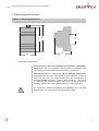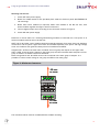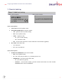
1
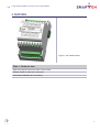
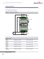
USER MANUAL
Longo programmable controller
LPC-2.DO6 module
Version 8
SMARTEH d.o.o. / Trg tigrovcev 1 / 5220 Tolmin / Slovenia / Tel.: +386(0) 388 44 00 / e-mail: [email protected] / www.smarteh.si
Longo programmable controller LPC-2.DO6 module
Written by SMARTEH d.o.o.
Copyright © 2005-2012, SMARTEH d.o.o.
User Manual
Document Version: 008
July 1, 2012
i
Longo programmable controller LPC-2.DO6 module
STANDARDS AND PROVISIONS: Standards, recommendations, regulations
and provisions of the country in which the devices will operate, must
be considered while planning and setting up electrical devices. Work
on 230 VAC network is allowed for authorized personnel only.
DANGER WARNINGS: Devices or modules must be protected from
moisture, dirt and damage during transport, storing and operation.
WARRANTY CONDITIONS: For all modules LONGO LPC-2 – if no
modifications are performed upon and are correctly connected by
authorized personnel – in consideration of maximum allowed
connecting power, we offer warranty for 24 months from date of sale
to end buyer. In case of claims within warranty time, which are based
on material malfunctions the producer offers free replacement. The
method of return of malfunctioned module, together with description,
can be arranged with our authorized representative. Warranty does
not include damage due to transport or because of unconsidered
corresponding regulations of the country, where the module is
installed.
This device must be connected properly by the provided connection
scheme in this manual. Misconnections may result in device damage,
fire or personal injury.
Hazardous voltage in the device can cause electric shock and may
result in personal injury or death.
NEVER SERVICE THIS PRODUCT YOURSELF!
This device must not be installed in the systems critical for life (e.g.
medical devices, aircrafts, etc.).
If the device is used in a manner not specified by the manufacturer,
the degree of protection provided by the equipment may be impaired.
Waste electrical and electronic equipment (WEEE) must be collected
separately!
LONGO LPC-2 complies to the following standards:
• EMC:EN 61000-6-2 (EN 50082), EN 61000-6-4 (EN 50081)
• LVD: IEC 61131-2
• Vibrations and climatic-mechanical: EN 60068-2-6, EN 60068-2-27,
EN 60068-2-29
Smarteh d.o.o. operates a policy of continuous development.
Therefore we reserve the right to make changes and improvements to
any of the products described in this manual without any prior notice.
MANUFACTURER:
SMARTEH d.o.o.
Trg tigrovcev 1
5220 Tolmin
Slovenia
ii
Longo programmable controller LPC-2.DO6 module
Longo programmable controller LPC-2.DO6 module
1 DESCRIPTION...................................................................................1
2 FEATURES.......................................................................................2
3 INSTALLATION..................................................................................3
3.1 Connection scheme....................................................................3
3.2 Mounting instructions.................................................................5
3.3 Module labeling........................................................................7
4 TECHNICAL SPECIFICATIONS..................................................................8
5 CHANGES .......................................................................................9
6 NOTES..........................................................................................10
iii
Longo programmable controller LPC-2.DO6 module
1 DESCRIPTION
LPC-2.DO6 is an eight relay digital output module with make contacts (NO). It can be used in a wide
range of applications, but is not suitable to be use with heavy inductive loads (reflectors,
contractors, motors etc...).
While using inductive loads it is recommended to use standard suppression circuits or in worse cases
use another type of digital output (e.g. triac module like LPC-2.DO9).
LEDs indicate each relay's contacts state. If a LED is on, the module's connection pins for the
correspondent relay are shorted (refer to the Table 5).
Module is powered from internal BUS.
NOTE: For proper system configuration and data allocation please refer to LPC Composer software
help menu.
1
Longo programmable controller LPC-2.DO6 module
2 FEATURES
Figure 1: LPC-2.DO6 module
Table 1: Technical data
Eight relay digital output with make contacts (NO)
Flexible output for wide use of operation
Standard DIN EN50022-35 rail mounting
2
Longo programmable controller LPC-2.DO6 module
3 INSTALLATION
3.1 Connection scheme
Figure 2: Connection scheme
LOAD
LED5 - LED8
K1
K2
LED1 - LED4
U
LOAD
Table 2: OUT1
1
OUT1.1
OUT1.2
Voltage free contacts
Make contacts (NO)
OUT2.3
OUT2.4
Voltage free contacts
Make contacts (NO)
OUT3.5
OUT3.6
Voltage free contacts
Make contacts (NO)
OUT4.7
OUT4.8
Voltage free contacts
Make contacts (NO)
OUT5.9
OUT5.10
Voltage free contacts
Make contacts (NO)
Wires connected to the module must have cross sectional area at least 0.75 mm 2. Minimum temperature rating of wire
insulation must be 85 °C.
3
Longo programmable controller LPC-2.DO6 module
Table 2: OUT
OUT6.11
OUT6.12
Voltage free contacts
Make contacts (NO)
OUT7.13
OUT7.14
Voltage free contacts
Make contacts (NO)
OUT8.15
OUT8.16
Voltage free contacts
Make contacts (NO)
Data & DC power supply
Connection to I/O module
Data & DC power supply
Connection to I/O module
Table 3: K1
Internal BUS
Table 4: K2
Internal BUS
Table 5: LED1 – LED8
Status
Digital
output
state
On: Output voltage present between OUT1.1 to OUT1.2 up to
Output voltage present between OUT8.15 to OUT8.16
Off: Output voltage not present between OUT1.1 to OUT1.2 up to
Output voltage not present between OUT8.15 to OUT8.16
4
Longo programmable controller LPC-2.DO6 module
3.2 Mounting instructions
36
60
53
•
95
90
Figure 3: Housing dimensions
Dimensions in millimeters.
EXTERNAL SWITCH OR CIRCUIT-BREAKER AND EXTERNAL OVERCURRENT
PROTECTION: The unit is allowed to be connected to installation with
over current protection that has nominal value of 16 A or less.
RECOMMENDATION ON SWITCH OR CIRCUIT-BREAKER PROTECTION:
There should be two poles main switch in the installation in order to
switch off the unit. The switch should meet the requirements of
standard IEC60947 and have a nominal value at least 6 A. The switch
or circuit-breaker should be within easy reach of the operator. It
should be marked as the disconnecting device for the equipment.
All connections, module attachments and assembling must be done
while module is not connected to the main power supply.
5
Longo programmable controller LPC-2.DO6 module
Mounting instructions:
1. Switch OFF main power supply.
2. Mount LPC-2.DO6 module to the provided place inside an electrical panel (DIN EN50022-35
rail mounting).
3. Mount other LPC-2 modules (if required). Mount each module to the DIN rail first, then
attach modules together through K1 and K2 connectors.
4. Connect digital output wires according to the connection scheme in Figure 2.
5. Switch ON main power supply.
Dismount in reverse order. For mounting/dismounting modules to/from DIN rail a free space of at
least one module must be left on the DIN rail.
NOTE: LPC-2.MC3 main control module should be powered separately from other electrical appliance
connected to LPC-2 system. Signal wires must be installed separately from power and high voltage
wires in accordance with general industry electrical installation standard.
Outputs OUT1..OUT4 on the lower side of module form one group and outputs on the upper side,
OUT5..OUT8, forms the other. Outputs in the same group are basic insulated while outputs from one
group to another are double/reinforced insulated.
Mains voltage 230 V and 48 V SELV must not be connected in the same group of outputs. It is
possible to connect mains voltage in one group and SELV in the other group.
Figure 4: Minimum clearances
60 mm
or more
60 mm
or more
The clearances above must be considered before module mounting.
6
Longo programmable controller LPC-2.DO6 module
3.3 Module labeling
Figure 5: Labels on housing
Label 1 (MC3 sample):
Label 2 (MC3 sample):
Label 1 description:
1. LPC-2.MC3 is the full product name.
2. P/N:225MC3040001001 is the part number.
•
225 – general code for product family,
•
MC3 – short product name,
•
04001 – sequence code,
•
•
04 – year of code opening
•
001 – derivation code
001 – version code (reserved for future HW and/or SW firmware upgrades).
3. D/C:16/05 is the date code.
•
16 – week and
•
05 – year of production.
Label 2 description:
1. S/N:MC3-S9-0500000190 is the serial number.
•
MC3 – short product name,
•
S9 – user code (test procedure, e.g. Smarteh person xxx),
•
0500000190 – year and current stack code,
•
05 – year (last two cyphers)
•
00000190 – current stack number; previous module would have the stack number
00000189 and the next one 00000191.
7
Longo programmable controller LPC-2.DO6 module
4 TECHNICAL SPECIFICATIONS
Table 6: Technical specifications
Power supply
from internal BUS
Power consumption
2.75 W
Output
8 relay make contacts (NO),
non-protected
Max. switching power per channel2
(resistive load)
AC: 230 V, 3 A
Min. permitted load per channel
100 mA at 5 VDC
Connection type
screw type connector for stranded wire 0.75 to
2.5 mm2
Dimensions (L x W x H)
90 x 53 x 60 mm
Weight
140 g
Ambient temperature
0 to 50 °C
Ambient humidity
max. 95 %, no condensation
Maximum altitude
2000 m
Mounting position
vertical
Transport and storage temperature
-20 to 60 °C
Pollution degree
2
Over voltage category
II
Electrical equipment
Class II (double insulation)
Protection class
IP 30
DC: 48 V, 1 A
30 V, 3 A
* NOTE: Inductive loads are influencing the relay contacts by shortening their working life period. It
is recommended to use standard suppression circuits or in worse cases use another type of digital
output (e.g. triac).
2 This specification is valid only for products with serial number within 564.. 593 and all greater than 865.
For products with different serial No. specification are: AC: 230V, 0.5A; DC 30V 1A
8
Longo programmable controller LPC-2.DO6 module
5 CHANGES
The following table describes all the changes to the document.
Date
V.
Description
1.7.2012
008
CGP General update and technical data update.
11.5.2010
007
Updated warranty permanence.
19.12.2009
006
Changed specification for the max. switching capability
13.6.2007
005
- improved output functioning in heavier conditions (noise, inductive
loads)
23.2.2006
004
- Added output isolation description
- Added output protection type description
- Pollution degree changed to 2
30.6.2005
003
The initial version, issues as LPC-2.DO6 module UserManual.
9
Longo programmable controller LPC-2.DO6 module
6 NOTES
10