1
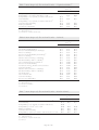
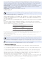
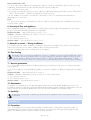
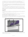
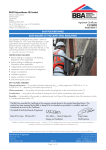
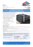
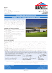
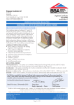
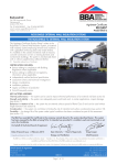
BASF Polyurethanes UK Ltd
APPROVAL
INSPECTION
TESTING
CERTIFICATION
Alfreton Trading Estate
Wimsey Way
Somercotes
Alfreton
Derbyshire DE55 4NL
Tel: 01773 601166 Fax: 01773 602089
TECHNICAL APPROVALS FOR CONSTRUCTION
Agrément Certificate
11/4816
e-mail: [email protected]
website: www.walltite.basf.co.uk
Product Sheet 1
BASF POLYURETHANES
WALLTITE
PRODUCT SCOPE AND SUMMARY OF CERTIFICATE
This Certificate relates to WALLTITE, a spray-applied
expanding polyurethane foam, for use as an in-situ
thermal insulation system for roofs, ground floors and
external walls of new and existing domestic or similar
buildings. It is for use in timber frame cavities, between
and under timber rafters, and to the internal surface of
masonry walls and concrete ground floors.
AGRÉMENT CERTIFICATION INCLUDES:
• factors relating to compliance with Building
Regulations where applicable
• factors relating to additional non-regulatory
information where applicable
• independently verified technical specification
• assessment criteria and technical investigations
• design considerations
• installation guidance
• regular surveillance of production
• formal three-yearly review.
KEY FACTORS ASSESSED
Practicability of installation — the product must only be installed by contractors trained and approved by the
Certificate holder (see section 4).
Thermal performance — when installed at an appropriate thickness, the product can enable elements to meet or
improve on U values specified for notional and existing buildings (see section 5).
Condensation risk — the product has a water vapour resistivity of approximately 306 MN·s·g–1·m–1 but the risk of
interstitial condensation will depend on the construction and should be assessed for each project (see section 6).
Behaviour in relation to fire — roof, floor and wall systems using this product can be designed to meet UK
requirements (see section 7).
Durability — the durability of the product is satisfactory and will have a life equivalent to that of the structure in which it
is incorporated (see section 13).
The BBA has awarded this Agrément Certificate to the company named above for the product described
herein. The product has been assessed by the BBA as being fit for its intended use provided it is installed, used
and maintained as set out in this Certificate.
On behalf of the British Board of Agrément
Date of First issue: 21 February 2011
Simon Wroe
Head of Approvals — Physics
Greg Cooper
Chief Executive
The BBA is a UKAS accredited certification body — Number 113. The schedule of the current scope of accreditation for product certification is
available in pdf format via the UKAS link on the BBA website at www.bbacerts.co.uk
Readers are advised to check the validity and latest issue number of this Agrément Certificate by either referring to the BBA website or contacting the BBA direct.
British Board of Agrément
Bucknalls Lane
Garston, Watford
Herts WD25 9BA
©2011
Page 1 of 16
tel: 01923 665300
fax: 01923 665301
e-mail: [email protected]
website: www.bbacerts.co.uk
Regulations
In the opinion of the BBA WALLTITE, if used in accordance with the provisions of this Certificate, will meet or
contribute to meeting the relevant requirements of the following Building Regulations:
The Building Regulations 2010 (England and Wales)
Requirement: A1
Loading
Comment:
Requirement: C2(c)
Resistance to moisture
Masonry floors incorporating the product can meet this Requirement. See section 10 of this Certificate.
Comment:
The risk of interstitial condensation must be assessed for each construction. The product can adequately
limit the risk of surface condensation. See sections 6.1 and 6.7 of this Certificate.
Requirement: L1(a)(i)
Conservation of fuel and power
Comment:
Requirement: Regulation 7
Materials and workmanship
Comment:
The product is an acceptable material. See section 13 and the Installation part of this Certificate.
The product can contribute to meeting this Requirement. See sections 5.1 and 5.2 of this Certificate.
The Building (Scotland) Regulations 2004 (as amended)
Regulation:
8(1)
Regulation:
Standard:
9
1.1(a)(b)
3.15
6.1(b)
6.2
Carbon dioxide emissions
Building insulation envelope
The product can contribute to a roof, floor or wall satisfying these Standards, with reference to clauses,
or parts of, 6.1.1(1), 6.1.2(2), 6.1.3(1), 6.1.6(1), 6.2.1(1)(2), 6.2.3(1), 6.2.4(2), 6.2.5(2), 6.2.6(1), 6.2.7(1),
6.2.8(1)(2) to 6.2.11(1)(2), 6.2.12(2) and 6.2.13(1)(2). See sections 5.1 and 5.2 of this Certificate.
Comment:
Regulation:
Condensation
The risk of interstitial condensation must be assessed for each construction. The product can adequately
limit the risk of surface condensation, with reference to clauses 3.15.1(1)(2), 3.15.3(1)(2), 3.15.4(1)(2),
3.15.5(1)(2), 3.15.6(1)(2) and 3.15.7(1)(2). See sections 6.1 and 6.8 of this Certificate.
Comment:
Standard:
Standard:
Building Standards — construction
Structure
Masonry floors incorporating the product can meet this Standard, with reference to clause 1.1.1(1)(2). See
section 10 of this Certificate.
Comment:
Standard:
Fitness and durability of materials and workmanship
The product can contribute to a construction satisfying this Regulation. See section 13 and the Installation
part of this Certificate.
Comment:
12
Building standards — conversions
All comments given for these products under Regulation 9, also apply to this Regulation, with reference to
clause 0.12.1(1) and Schedule 6(1).
Comment:
(1) Technical Handbook (Domestic).
(2) Technical Handbook (Non-Domestic).
The Building Regulations (Northern Ireland) 2000 (as amended)
Regulation:
B2
Fitness of materials and workmanship
Comment:
Regulation:
C5
Condensation
Comment:
Regulation:
D1
Stability
Comment:
Regulation:
Regulation:
F2(a)(i)
F3(2)
Conservation measures
Target carbon dioxide Emissions Rate
Comment:
The product is acceptable. See section 13 and the Installation part of this Certificate.
The risk of interstitial condensation must be assessed for each construction. See section 6.1 of this Certificate.
Masonry floors incorporating the product can meet this Regulation. See section 10 of this Certificate.
The product can contribute to meeting these Regulations. See sections 5.1 and 5.2 of this Certificate.
Construction (Design and Management) Regulations 2007
Construction (Design and Management) Regulations (Northern Ireland) 2007
Information in this Certificate may assist the client, CDM co-ordinator, designer and contractors to address their
obligations under these Regulations.
See sections:
2 Delivery and site handling (2.1 to 2.3) and 14 Precautions (14.1 to 14.6) of this Certificate.
Non-regulatory Information
NHBC Standards 2011
NHBC accepts the use of WALLTITE, when installed and used in accordance with this Certificate, in relation to
NHBC Standards, Chapter 5.1 Substructure and ground bearing floors Chapter 5.2 Suspended ground floors,
Chapter 6.1 External masonry walls, Chapter 6.2 External timber framed walls, Chapter 7.1 Flat roofs and balconies
and Chapter 7.2 Pitched roofs.
Page 2 of 16
General
WALLTITE is a registered trademark of BASF Polyurethanes UK Ltd.
Technical Specification
1 Description
1.1 WALLTITE comprises a spray applied HFC blown, rigid polyurethane foam which can be applied to pitched
timber roofs, including hybrid(1) roofs, flat timber roofs, concrete ground-floor constructions, timber-frame stud walling
and the internal surfaces of external masonry walls.
(1) Hybrid roofs contain both sloping and horizontal insulation.
1.2 The foam is prepared by mixing two liquid components, (one part by volume of isocyanate to one part by volume
of resin) within the nozzle of the spray gun during the spraying process. The thermal insulation system is built up in
layers not exceeding 20 mm in thickness, until the required thickness is achieved. It is fully cured within two hours.
1.3 Quality control arrangements on site include checks on density and appearance.
1.4 Ancillary items used with the product, but outside the scope of this Certificate include:
• BASF rafter slides — corrugated cardboard used to create a 50 mm ventilation gap between the bitumen felt/
sarking board and WALLTITE
• BASF ventilator – a polyvinyl chloride ventilator, used at the eaves and/or ridge to create a 50 mm ventilation gap
between the bitumen felt/sarking board and WALLTITE. It also keeps the eaves clear of WALLTITE.
2 Delivery and site handling
2.1 The two components are delivered to site in drums (up to 250 kg capacity) bearing the product name, batch
number and the BBA identification mark incorporating the number of this Certificate.
2.2 Drums should be stored in a well-ventilated area, ideally above 10°C and away from possible ignition sources.
The drums must be protected from frost.
2.3 The isocyanate component is classified as ‘harmful’, under The Chemicals (Hazard Information and Packaging for
Supply) Regulations 2009 (CHIP4) and drums bear the appropriate hazard warning sign. When cured, the product
does not constitute a health hazard.
Assessment and Technical Investigations
The following is a summary of the assessment and technical investigations carried out on WALLTITE.
Design Considerations
3 General
3.1 WALLTITE is satisfactory for use as an insitu thermal insulation system to reduce the thermal transmittance (U value)
of roofs, floors and walls in new or existing domestic, or similar buildings.
3.2 The product can be used:
• between timber rafters only
• between and under timber rafters
• as a combination between and under timber rafters and between ceiling joists in a non-habitable roof (hybrid roof,
which contain both sloping and horizontal insulation)
• between timber joists in flat roofs
• Concrete ground floors
• between the studs of conventional timber-frame external wall constructions
• between the void created by timber battens on the internal face of external masonry(1) walls, and lined with plasterboard.
(1) Masonry constructions include clay and calcium silicate bricks, concrete blocks, and natural and reconstituted stone blocks. It is essential that
such walls are constructed having regard to the local wind-driven rain index.
3.3 New constructions must be designed in accordance with
• BS 5250 : 2002
• BS 5534 : 2003
• BS 8102 : 2009
• BS 8103-3 : 1996
• BS 8215 : 1991
• BS 8000-3 : 2001
• BS EN 1996-1-1 : 2005
• BS EN 1996-1-2 : 2005
the relevant recommendations of:
• BS 5628-3 : 2005
• BS 6229 : 2003
• BS 8204-1 : 2003
• BS 8204-2 : 2003
• BS 8000-9 : 2003
• BS EN 1995-1-1 : 2004
• BS EN 1996-2 : 2006 • BS EN 1996-3 : 2006.
(1) Further information is given in BRE Report (BR 262 : 2002) Thermal insulation : avoiding risks.
Page 3 of 16
3.4 Existing constructions must be in a good state of repair with no evidence of rain penetration or damp. Defects
must be made good prior to installation.
3.5 If present, mould or fungal growth must be treated prior to the application of the product.
3.6 The product must not come into direct contact with flue pipes, chimneys or other heat producing appliances (see
section 8).
3.7 It is essential that construction elements are designed and constructed to incorporate normal precautions against
moisture ingress before the application of the product.
3.8 The product forms a strong bond with clean and dry substrates. This should be taken into account when specifying
the product or anticipating future alterations.
3.9 The product can contribute to the airtightness of the building envelope.
3.10 To satisfy the requirements of NHBC, a vapour control layer (VCL) of a type specified in their Standards must be
applied behind the plasterboard lining in roof and wall applications, and the product must only be applied to a roof
construction incorporating a breathable roof tile underlay.
Pitched roofs, including hybrid roofs tiled or slated to BS 5534 : 2003
3.11 The product can be applied directly to breathable roof tile underlays, or to the BASF rafter slides and BASF
ventilators which create a ventilation gap between the insulation and the bitumen felt/sarking board. Additionally, the
product is applied to plasterboard, between ceiling joists to create a hybrid roof.
3.12 Care must be taken to ensure the integrity of the roof tile underlay drape when spraying the product (see section 15.4).
3.13 Pitched roofs are defined for the purpose of this Certificate as those roofs having a pitch in excess of 15°.
Concrete ground floor constructions
3.14 The product must not be used where it may come into contact with moisture from the ground.
3.15 Ground-supported concrete floors incorporating the product must include a suitable damp-proof membrane (dpm)
laid in accordance with the relevant clauses of CP 102 : 1973, BS 8102 : 1990 and/or BS 8215 : 1991.
3.16 Concrete ground floors incorporating the product must include a dpm or suitable ventilation of the sub-floor as
appropriate.
3.17 The overlay should be:
• a cement-based floor screed, laid in accordance with the relevant clauses of BS 8204-1 : 2003 and/or BS 8204-2 :
2003, and BS 8000-9 : 2003, or
• a concrete slab in accordance with BS 8204-1 : 2003 and BS 8204-2 : 2003.
External masonry walls (insulated dry lining)
3.18 Insulated dry lining systems require careful detailing during installation around doors and windows to achieve
a satisfactory surface for finishing. In addition, every attempt should be made to minimise the risk of thermal bridging
at reveals and where heavy separating walls are attached to the external wall. New work must be designed to
accommodate the thickness of the dry lining, particularly at reveals, heads, sills and in relation to ceiling height. Where
the dimensions of fixtures are critical (eg bathrooms) these should be checked before installation.
3.19 It is recommended that services which penetrate the dry lining, eg, light switches, power outlets, are kept to a
minimum to limit damage to vapour checks.
External walls (timber-frame)
3.20 Constructions incorporating a masonry outer leaf (such as masonry units and natural stone blocks) should be
in accordance with BS EN 1996-1-1 : 2005, BS EN 1996-1-2 : 2005, BS EN 1996-2 : 2006, BS EN 1996-3 :
2006, BS 5628-3 : 2005 and BS 8000-3 : 2001. The designed residual cavity width should be 50 mm wide.
3.21 It is recommended that services which penetrate the dry lining, eg, light switches, power outlets, are kept to a
minimum to limit damage to vapour checks. In addition, any penetrations should be either enclosed in plasterboard or
stone mineral wool or suitably tested proprietary fire-rated systems in order to preserve the fire resistance of the wall.
3.22 Installation must not be carried out until the moisture content of the timber frame is less than 20%.
4 Practicability of installation
The product must only be installed by contractors trained and approved by the Certificate holder in accordance with
the Certificate holder’s Installation Manual.
5 Thermal performance
5.1 Calculations of the thermal transmittance (U value) should be carried out in accordance with
BS EN ISO 6946 : 2007 and BRE Report (BR 443 : 2006) Conventions for U-value calculations using the
thermal conductivity values in Table 1. Example U values for pitched roofs, flat roofs, floors and walls are given
in Tables 2 to 4 and typical design roof, floor and wall U values in Tables 5 to 7. Fortuitous air infiltration in hybrid
roofs increases the heat loss from the loft void and should be accounted for by adding a 10% correction factor to the
calculated roof U value (see Table 3).
Page 4 of 16
Table 1 Thermal conductivity
Insulation thickness
(mm)
Thermal conductivity
(W·m–1·K–1)
<80
0.027
80 to 120
0.026
>120
0.025
Table 2 U values (1) for pitched and flat roofs and timber frame walls
Element type
Timber dimensions (mm)
WALLTITE insulation (mm) and location
with respect to rafter/joist/batten or stud
Existing sloping
roof with ventilated
space below
underlay
Rafters = 50 x 150
at 400 centres
Battens (inside) = 47 x 100
at 600 centres
New sloping roof
with LR underlay
Rafters = 47 x 200
at 600 centres
Flat timber roof
Joists = 50 x 150
at 400 centres
Timber frame wall
(1)
(2)
(3)
(4)
(5)
U value
(W·m–2·K–1)
inside
between
100
50
0.20
(2)
26
141
161
185
200
0.20
0.18
0.16
0.13
7(3)
20(2)
50(4)
150
150
150
0.20
0.18
0.15
32(5)
92
102
121
140(3)
140
0.30
0.28
0.25
0.22
0.19
Studs = 38 x 140
at 600 centres
Plasterboard taken as 12.5 mm at 0.25 W·m–1·K–1 and all timber % taken from BR 443.
Timber batten = 47 mm x 30 mm at 600 mm centres.
Timber batten = 47 mm x 22 mm at 600 mm centres.
Timber batten = 47 mm x 60 mm at 600 mm centres.
Timber batten = 47 mm x 32 mm at 600 mm centres.
Table 3 Hybrid pitched roof U values including a 10% correction factor, calculated to section 8
of BR 443 : 2006 (Insulation at rafter level – flat ceiling)
Roof pitch (θ):
U value
(W·m–2·K–1)
20
30
40
50
60
0.18
0.18
0.19
0.20
0.22
Note: Assuming construction of roof (external to internal):
• 100 mm WALLTITE (91.6% )/100 mm deep timber rafters
• loft void air cavity resistance 0.16 m2·K·W–1
• 100 mm WALLTITE (91.6%)/timber ceiling joists
• plasterboard – 12.5 mm.
Table 4 Slab on ground support U values (1)(2)
P/A (perimeter/area)
Insulation thickness
(mm)
Construction U value
(W·m–2·K–1)
0.20
50
0.20
0.25
50
0.22
0.30
50
0.24
0.25
75
0.18
0.30
75
0.20
0.45
75
0.22
0.70
75
0.25
0.35
120
0.15
0.90
120
0.18
(1) Edge insulation not included.
(2) Wall thickness (w) 0.3 m.
Page 5 of 16
Table 5 Mean design roof, floor and wall U values — England and Wales (1)
Construction
U value
(W·m–2·K–1)
Existing building – new or replaced floor or wall
Existing building – renovated or retained floor or wall
Existing building – new, replaced, renovated or retained roof(2)
Notional dwelling
Existing building – new, replaced, renovated or retained roof(3)
Notional non-domestic building
Dwelling new-build limit
Non-domestic new-build limit
Roof
Floor
Wall
—
—
0.16
0.16
0.18
0.18
0.20
0.25
0.22
0.25
––
0.25
—
0.22
0.25
0.25
0.28
0.30
––
0.35
—
0.26
0.30
0.35
(1) Flexible approaches on existing buildings are given in the Approved Documents.
(2) Hybrid pitched roof.
(3) Pitched roof – insulation at rafter level.
Table 6 Mean design roof, floor and wall U values – Scotland (1)
Construction
U value
(W·m–2·K–1)
Notional dwelling
New dwelling simplified method
Conversion unheated building (into dwellings)(2)
Extension to dwelling(2)
Conversion of unheated building (into dwellings)(3)
Extension to dwelling(3)
Alterations and reconstructions to a dwelling(2)
Stand-alone building < 50 m2 to a dwelling(2)
New non-dwellings limit for shell and fit out
Conversion of unheated building
Non-domestic extension, alterations and reconstructions
Notional non-dwelling(4)
Alterations and reconstructions to a dwelling(3)
Stand-alone building < 50 m2 to a dwelling(3)
New dwelling limit
New non-domestic limit
Notional non-dwelling(3)
Conversion of heated building
(1)
(2)
(3)
(4)
Roof
Floor
Wall
0.13
0.13
0.13
0.13
0.15
0.15
0.15
0.15
0.15
0.15
0.15
0.16
0.18
0.18
0.18
0.20
0.25
0.25
0.15
0.15
0.15
0.15
0.15
0.15
0.18
0.18
0.20
0.20
0.20
0.25
0.18
0.18
0.20
0.22
0.25
0.25
0.19
0.19
0.19
0.19
0.19
0.19
0.22
0.22
0.23
0.25
0.25
0.30
0.22
0.22
0.25
0.27
0.30
0.30
Flexible approaches on existing buildings are given in the Technical Handbooks.
Hybrid pitched roof.
All other roof insulation.
Pitched roof.
Table 7 Mean design roof, floor and wall U values – Northern Ireland (1)
Construction
U value
(W·m–2·K–1)
Existing building – new, replaced, renovated or retained roof
Notional dwelling
Existing building – new, replaced, renovated or retained roof (3)
Existing building – new roof (4), floor or wall
Building new-build limit
Notional non-domestic building
Existing building – replaced, renovated or retained roof (4), floor or wall
(2)
Roof
Floor
Wall
0.16
0.16
0.20
0.20
0.25
0.25
0.25
––
0.25
—
0.22
0.25
0.25
0.25
––
0.35
—
0.30
0.35
0.35
0.35
(1) Flexible approaches on existing buildings are given in the Technical Booklets.
(2) Hybrid pitched roof.
(3) Pitched roof – insulation at rafter level.
(4) Flat roof.
Page 6 of 16
5.2 The product can maintain, or contribute to maintaining, continuity of thermal insulation at junctions between
elements and openings. Default psi values in BRE Information Paper IP1/06 Assessing the effects of thermal bridging
at junctions and around openings, Table 3 may be used in carbon emission calculations in Scotland and Northern
Ireland. Detailed guidance for other junctions and on limiting heat loss by air infiltration can be found in:
England and Wales — Approved Documents to Part L and for new thermal elements to existing buildings, Accredited
Construction Details (version 1.0). See also SAP 2009 Appendix K and the iSBEM User Manual for new-build
Scotland — Accredited Construction Details (Scotland)
Northern Ireland — Accredited Construction Details (version 1.0).
6 Condensation risk
Interstitial condensation
6.1 Roofs, floors and walls should be designed and constructed in accordance with the relevant parts of
BS 5250 : 2002 and Annex D, and BRE Report (BR 262 : 2002) for roofs and floors in England and Wales,
including a well-sealed ceiling for the roof application, or BS EN 15026 : 2007, using the approximate water
vapour resistivity value of 306 MN·s·g–1·m–1 for the product.
6.2 It is essential that roof, floor or wall design, construction and maintenance not only limits opportunities for vapour
migration by diffusion but also by convection through gaps, cracks and laps in air/vapour control layers and through
penetrations. This is particularly important for roofs which include layers of high resistance to vapour diffusion on both
sides of the insulation layer.
6.3 Care should be taken to provide adequate ventilation, particularly in rooms expected to experience high humidity.
Roofs
6.4 Dynamic simulations to BS EN 15026 : 2007 indicate that the VCL properties (with sealed laps) detailed in
Table 8 are acceptable in roofs with no penetrations. The suitability of other constructions may be assessed by using an
appropriate dynamic modelling package, see section 16.2.
Table 8 Vapour control layer properties
VCL equivalent air layer
thickness sd
(m)
VCL water vapour
resistance
(MN·s·g–1)
Roof type
10
50
Flat roof
10
50
Hybrid pitched roof
6.5 If the product is installed in roofs with bitumen felt/sarking board, a ventilation gap, minimum 50 mm from eaves
to ridge must be provided to the underside of the roof tile underlay and the upper face of the insulation, unless a
vapour permeable underlay is used.
6.6 Inadvertent air infiltration in hybrid roofs contributes to reducing the risk of interstitial condensation.
Surface condensation
6.7 Roofs, floors and walls will adequately limit the risk of surface condensation where the thermal transmittance
(U value) does not exceed 0.7 W·m–2·K–1 for walls and floors and 0.35 W·m–2·K–1 for roofs at any point and
the junctions are designed in accordance with Limiting thermal bridging and air leakage : Robust construction
details for dwellings and similar buildings TSO 2002, BRE Information Paper IP1/06 or section 5.2 of this Certificate.
6.8 Roofs, floors and walls designed to BS 5250 : 2002, Section 8, will adequately limit the risk of surface
condensation where the thermal transmittance (U value) does not exceed 1.2 W·m–2·K–1 at any point. Guidance
may by obtained from, BRE Report (BR 262 : 2002) and section 5.2 of this Certificate.
7 Behaviour in relation to fire
7.1 The internal face of the installed product achieved a Class 1 surface spread of flame rating when tested in
accordance with BS 476-7 : 1997.
7.2 The product must be protected from naked flames and other ignition sources during and after installation (see also
sections 9.1, 9.2 and 14.5).
7.3 When installed, the product will be contained by a suitable lining board, eg 12.5 mm plasterboard, with all
joints fully sealed and supported by rafters, noggins or battens. Therefore, it will not contribute to the development
stages of a fire until the lining is compromised. Alternatively, the rafters and the insulation foam in the pitched roof
application may remain exposed after conducting a condensation risk analysis in accordance with section 6. Although
the insulation foam has a class 1 surface spread of flame rating to BS 476-7 : 1997, it could contribute to the
development stages of a fire, however to a limited extent in the early stages of the fire.
7.4 Elements must incorporate cavity barriers at edges, around openings, at junctions with fire resisting elements and
in cavities in accordance with the relevant provisions of the national Building Regulations and relevant purpose group.
The design and installation of cavity barriers must take into account any anticipated differential movement.
Page 7 of 16
External timber frame walls
7.5 The product can be added to the void between studwork, or used as a substitute for glass mineral wool, in any
loadbearing, timber-framed inner leaf to a double leaf wall system providing that:
• the outer leaf is masonry, and
• the existing inner leaf system has been shown to satisfy the loadbearing capacity performance criterion of BS 476-21 :
1987 or BS EN 1365-1 : 1999 for the required fire resistance period.
7.6 The suitability of constructions other than those described in section 7.5 should be demonstrated by an
appropriate test or assessment.
Roofs
7.7 The use of the product in a tiled pitched roof does not affect it’s external rating when evaluated by assessment or
test to BS 476-3 : 2004.
8 Proximity of flues and appliances
When installing the product in close proximity to certain flue pipes and/or heat producing appliances, the relevant
provisions of the national Building Regulations are applicable:
England and Wales — Approved Document J, sections 1 to 4
Scotland — Mandatory Standard 3.19, clauses 3.19.1(1)(2) to 3.19.9(1)(2)
(1) Technical Handbook (Domestic).
(2) Technical Handbook (Non-Domestic).
Northern Ireland — Technical Booklet L, sections 1 to 4.
9 Materials in contact — Wiring installations
9.1 De-rating of electric cables should be considered in areas where the product restricts the flow of air. Where the
foam is likely to bond to electric cables, suitable conduit or trunking must be used.
9.2 Recessed lighting must not be used with this form of insulation.
10 Floor loading
The product, when covered with a suitable floor covering, is capable of resisting a uniformly distributed load of
< 1.5 kN·m–2 and a concentrated load of < 1.4 kN for category A1 and type A situations for domestic and
residential activities as defined in NA to BS EN 1991-1-1 : 2002, Tables NA.2 and BS 6399-1 : 1996,
Table 1 respectively. Further assessment is necessary in the case of duty walkways and floors subject to physical activities.
11 Moisture penetration
11.1 The product must be used above the dpm and must not be used where it may come into contact with moisture
from the ground.
11.2 For floors subject to national Building Regulations, construction should be as detailed or designed in accordance
with:
England and Wales — Approved Document C, Section 4
Scotland — Mandatory Standard 3.4, clauses 3.4.2(1)(2) to 3.4.4(1)(2) and 3.4.6(1)(2)
(1) Technical Handbook (Domestic).
(2) Technical Handbook (Non-Domestic).
Northern Ireland — Technical Booklet C, Section 1.
12 Maintenance
The product once installed does not require any regular maintenance and has suitable durability (see section 13),
provided the waterproof layers are inspected and maintained at regular intervals. In pitched roof applications when the
foam is exposed, any accidental damage that occurs can easily be rectified by the Certificate holder.
13 Durability
The durability of the product is satisfactory and will have a life equivalent to that of the structure in which it is
incorporated.
Installation
14 Precautions
14.1 The installation process may produce a build-up of harmful vapours, and ventilation must be provided. It is
required that all personnel in the area for treatment wear the correct protective clothing, breathing equipment and
gloves. The Certificate holder’s instructions must be followed at all times.
Page 8 of 16
14.2 Vapours given off by certain components, ie 4,4’ diphenylmethane diisocyanate (MDI), are generally heavier
than air and will tend to move to lower parts of the building. These parts should be suitably ventilated.
14.3 If vapour levels need to be measured, methods should be those recommended by the Health and Safety
Executive. Certain applications, ie confined roofs, require the use of extractor fans as recommended by the Certificate
holder.
14.4 To comply with the requirements of Section 4 of the Health and Safety at Work Act 1974, it is essential that
there is an exchange of information between the client and the installer before spray operations commence on any site.
Existing health hazards and those brought into the premises by the installer should be discussed and measures agreed
to deal with them effectively.
14.5 After installation in loft voids, fire warning labels must be placed in prominent positions if the foam is to be left
exposed. The foam is a combustible material; adequate precautions should be taken to avoid ignition at all times.
14.6 To prevent the product from entering the occupied space, the loft hatch/cover must be kept closed during the
spraying process. Protective covers must be placed over water tanks to prevent contamination and blockage during
application, and should not be removed until sufficient time has elapsed for potentially harmful vapours to be ventilated
from the roof space.
15 Procedure
General
15.1 Building elements to be insulated must be assessed for suitability and any necessary repairs carried out. Elements
must be weather tight before the application of the product. The positioning and access to services should also be
considered.
15.2 Access boards and lighting should be positioned in the roof void.
15.3 Where there is no provision made for ventilation of the space, care should be taken to ensure that ingress of
moisture vapour from the dwelling space below is restricted (see also sections 6.1 and 6.2).
Between rafters application — breathable roof tile underlay (see Figure 1)
15.4 The product should be spray applied to clean and dry substrates in a flash coat, <10 mm thick. Care must be
taken to ensure the integrity of the roof tile underlay drape. Subsequent coats not exceeding 20 mm thick are applied
once the foam reaction has occurred, and within 10 minutes of the previous coat being applied, until the required total
thickness is achieved.
Figure 1 Typical pitched roof application
roof tile underlay
Walltite
plasterboard
VCL
15.5 Where additional insulation to that provided in sections 15.4, 15.6 and 15.7 is required, insulation can be
placed between the horizontal ceiling joists in the form of mineral wool or WALLTITE, after conducting a condensation
risk analysis in accordance with section 6.
Page 9 of 16
Between rafters application – bitumen felt/sarking board
15.6 BASF ventilator spacers are tightly fitted at the eaves to fully fill the space between the rafters (see Figure 2).
BASF rafter slides are then stapled to the internal face of the rafters, leaving a minimum 25 mm of rafter exposed below
the edges of the BASF rafter slides for the foam to adhere to (see Figure 3). A 50 mm deep ventilated void (minimum
of 25 mm at the centre of the underlay drape and the BASF ventilator spacers/BASF rafter slides) must be maintained.
The foam is spray applied to the depth of the rafters as in section 15.4.
Figure 2 BASF ventilator spacer detailing
BASF rafter slide
Walltite
BASF ventilator spacer
Figure 3 BASF rafter slide detailing
BASF rafter slide
Walltite
BASFventilator spacer
roof tile underlay
Between and below rafters
15.7 The foam is applied by spray to the depth of the rafters as shown in section 15.4. Cross-battens are then
mechanically fixed to the rafters. The battens must be of sufficient width and spacing (up to 600 mm) to provide
adequate support to which the plasterboard can be mechanically fixed. Filling then resumes in 20 mm thick layers.
Page 10 of 16
Flat roofs
15.8 The product is sprayed directly to the underside of the roof deck, as described in section 15.4.
Ground Floors
15.9 All concrete floor surfaces should be smooth, level and flat to within 5 mm when measured with a 2 m straightedge. Irregularities greater than this must be removed, whilst minor irregularities (up to 10 mm deep) may be levelled
with mortar or thin screed.
15.10 In ground-supported concrete floors, the concrete floor slab over which the product is spray applied should
be left for as long as possible to maximise drying out and dissipation of construction moisture, in accordance with
BS 8203 : 2001, Section 3.1.2.
15.11 Where the product is used over ground-supported concrete floor slabs a suitable dpm in accordance with
CP 102 : 1973, Section 11 and BS 8204-1 : 2003 or BS 8204-2 : 2003 should be laid to resist moisture from the
ground. If a liquid-type dpm is applied to the slabs, it should be of a type compatible with the product and be allowed
to dry out fully prior to installation of the product.
15.12 Ground floors with a hardcore base must be compacted and blinded with a thin layer of sand before laying
the dpm, product and concrete slab.
15.13 The product can be used on beam and block suspended concrete floors, that are the subject of a current
Agrément Certificate and installed in accordance with, and within the limitations imposed by that Certificate. It may
also be used on designed and installed precast concrete floors with general loading codes, which have been assessed
as suitable.
15.14 When a screed or concrete slab is to be laid over the product, vertical spray applied insulation should be
provided and be of sufficient depth to fully separate the screed or slab from the wall and provide a minimum thermal
resistance of 0.75 m2·K·W–1.
15.15 To limit the risk of damage from condensation and other sources of dampness, the product should only be
spray applied after the construction is made substantially weathertight, eg after glazing. During construction the product
must also be protected from water spillage, plaster droppings and traffic.
15.16 The foam is spray applied to the required depth as in section 15.4.
Cement-based screed overlay (see Figure 4)
15.17 The foam is spray applied to the wall, around the floor perimeter edges, to provide edge insulation. If required
a polythene VCL, minimum 0.125 mm thick, is laid over the product with 150 mm laps. A compacted screed is then
poured over to a depth of 65 mm for a domestic dwelling and 75 mm for others. The relevant clauses of BS 8204-1 :
2003 or BS 8204-2 : 2003 should be followed and BRE Report 460 : 2003 BRE building elements: floors and
flooring — performance, diagnosis, maintenance, repair and the avoidance of defects, Chapter 4.2, should be
consulted.
Figure 4 Typical ground floor application
dpm
Page 11 of 16
Walltite
Concrete slab overlay (ground-bearing only)
15.18 The foam is spray applied to the wall, around the floor perimeter edges, to provide edge insulation. If required
a VCL, minimum 0.125 mm thick, is laid over the boards with 150 mm laps. The concrete slab is laid to the required
thickness in accordance with BS 8000-9 : 2003 and BS 8204-1 : 2003.
Timber-frame walls (see Figure 5)
15.19 The product is sprayed into the cavity formed by the studs as in section 15.4.
15.20 Where required, a VCL with lapped and sealed joints is placed over the stud face before applying the
internal finish.
Figure 5 Typical timber-frame application
Walltite
VCL
plasterboard
Masonry external walls
15.21 Installation should be in accordance with good dry lining practice and the relevant parts of the Certificate
holder’s literature.
15.22 Before fixing the product, sufficient time must be allowed for damp-proofing treatments, where applied, to dry
out the wall (see also, BS 6576 : 2005 for dry lining in conjunction with a chemical dpc application).
15.23 This system may be used on any stable, dry wall capable of taking the fixings for the timber battens.
15.24 Wallpaper, skirting, picture rails, gloss paint and projecting window boards are removed.
15.25 Pre-treated timber battens of sufficient thickness are mechanically fixed to the wall substrate at maximum 600 mm
centres. Vertical battens are then fitted, with additional battens used around openings and to support heavy horizontal
items.
15.26 The product is sprayed into the cavity formed by the battens as in section 15.4. To avoid thermal bridging, the
product should be applied to window reveals.
15.27 An effective VCL with lapped and sealed joints is placed over the timber battens before applying the internal
finish, unless an assessment to BS 5250 : 2002 indicates that it is not necessary.
15.28 Jointing and finishing of the plasterboard lining is carried out in the appropriate manner applying plasterer’s
scrim to all joints and a thin coat of plaster. Timber skirting can be fixed into the horizontal batten at floor level.
Page 12 of 16
Technical Investigations
16 Investigations
16.1 Results of independent test data relating to WALLTITE were assessed in relation to:
• thermal conductivity
• behaviour in relation to fire
• water vapour permeability
• closed cell content
• dimensional stability under specified temperature and humidity conditions
• compressive strength
• compressive creep
• tensile adhesion strength.
16.2 A series of dynamic computer simulations to BS EN 15026 : 2007 were carried out on a range of roof
constructions to asses the risk of interstitial condensation. The simulations included building humidity class 4,
meteorological data for solar irradiation (direct and indirect) and rainfall for standard reference years, material moisture
storage functions, porosity, specific heat capacity and long term projections of material moisture contents.
16.3 The methods adopted for quality control, relating to incoming materials and the installed product, were
examined and found to be satisfactory.
Page 13 of 16
Bibliography
BS 476-3 : 2004 Fire tests on building materials and structures — Classification and method of test for external fire
exposure to roofs
BS 476-7 : 1997 Fire tests on building materials and structures — Method of test to determine the classification of the
surface spread of flame of products
BS 476-21 : 1987 Fire tests on building materials and structures — Methods for determination of the fire resistance of
loadbearing elements of construction
BS 5250 : 2002 Code of practice for control of condensation in buildings
BS 5534 : 2003 Code of practice for slating and tiling (including shingles)
BS 5628-3 : 2005 Code of practice for the use of masonry — Materials and components, design and workmanship
BS 6229 : 2003 Flat roofs with continuously supported coverings — Code of practice
BS 6399-1 : 1996 Loading for buildings — Code of practice for dead and imposed loads
BS 6576 : 2005 Code of practice for diagnosis of rising damp in walls of buildings and installation of chemical
damp-proof courses
BS 8000-3 : 2001 Workmanship on building sites — Code of practice for masonry
BS 8000-9 : 2003 Workmanship on building sites — Cementitious levelling screeds and wearing screeds — Code of
practice
BS 8102 : 1990 Code of practice for protection of structures against water from the ground
BS 8102 : 2009 Code of practice for protection of below ground structures against water from the ground
BS 8103-3 : 1996 Structural design of low-rise buildings — Code of practice for timber floors and roofs for housing
BS 8203 : 2001 Code of practice for installation of resilient floor coverings
BS 8204-1 : 2003 Screeds, bases and in-situ floorings — Concrete bases and cement sand levelling screeds to
receive floorings — Code of practice
BS 8204-2 : 2003 Screeds, bases and in-situ floorings — Concrete wearing surfaces — Code of practice
BS 8215 : 1991 Code of practice for design and installation of damp-proof courses in masonry construction
BS EN 1365-1 : 1999 Fire resistance tests for loadbearing elements — Walls
NA to BS EN 1991-1-1 : 2002 UK National Annex to Eurocode 1 : Actions on structures — General actions—
Densities, self-weight, imposed loads for buildings
BS EN 1995-1-1 : 2004 Eurocode 5 : Design of timber structures — General — Common rules and rules for buildings
BS EN 1996-1-1 : 2005 Eurocode 6 : Design of masonry structures — General rules for reinforced and unreinforced
masonry structures
BS EN 1996-1-2 : 2005 Eurocode 6 : Design of masonry structures — General rules — Structural fire design
BS EN 1996-2 : 2006 Eurocode 6 : Design of masonry structures — Design considerations, selection of materials and
execution of masonry
BS EN 1996-3 : 2006 Eurocode 6 : Design of masonry structures : Simplified calculation methods for unreinforced
masonry structures
BS EN 15026 : 2007 Hygrothermal performance of building components and building elements — Assessment of
moisture transfer by numerical simulation
BS EN ISO 6946 : 2007 Building components and building elements — Thermal resistance and thermal transmittance
— Calculation method
CP 102 : 1973 Code of practice for protection of buildings against water from the ground
Page 14 of 16
Conditions of Certification
17 Conditions
17.1 This Certificate:
• relates only to the product/system that is named and described on the front page
• is granted only to the company, firm or person named on the front page — no other company, firm or person may
hold or claim any entitlement to this Certificate
• is valid only within the UK
• has to be read, considered and used as a whole document — it may be misleading and will be incomplete to be
selective
• is copyright of the BBA
• is subject to English law.
17.2 Publications and documents referred to in this Certificate are those that the BBA deems to be relevant at the date
of issue or re-issue of this Certificate and include any: Act of Parliament; Statutory Instrument; Directive; Regulation;
British, European or International Standard; Code of Practice; manufacturers’ instructions; or any other publication or
document similar or related to the aforementioned.
17.3 This Certificate will remain valid for an unlimited period provided that the product/system and the manufacture
and/or fabrication including all related and relevant processes thereof:
• are maintained at or above the levels which have been assessed and found to be satisfactory by the BBA
• continue to be checked as and when deemed appropriate by the BBA under arrangements that it will determine
• are reviewed by the BBA as and when it considers appropriate.
17.4 In granting this Certificate, the BBA is not responsible for:
• the presence or absence of any patent, intellectual property or similar rights subsisting in the product/system or any
other product/system
• the right of the Certificate holder to manufacture, supply, install, maintain or market the product/system
• individual installations of the product/system, including the nature, design, methods and workmanship of or related
to the installation
• the actual works in which the product/system is installed, used and maintained, including the nature, design,
methods and workmanship of such works.
17.5 Any information relating to the manufacture, supply, installation, use and maintenance of this product/system
which is contained or referred to in this Certificate is the minimum required to be met when the product/system is
manufactured, supplied, installed, used and maintained. It does not purport in any way to restate the requirements
of the Health & Safety at Work etc Act 1974, or of any other statutory, common law or other duty which may exist
at the date of this Certificate; nor is conformity with such information to be taken as satisfying the requirements of the
1974 Act or of any statutory, common law or other duty of care. In granting this Certificate, the BBA does not accept
responsibility to any person or body for any loss or damage, including personal injury, arising as a direct or indirect
result of the manufacture, supply, installation, use and maintenance of this product/system.
Page 15 of 16
British Board of Agrément
Bucknalls Lane
Garston, Watford
Herts WD25 9BA
©2011
Page 16 of 16
tel: 01923 665300
fax: 01923 665301
e-mail: [email protected]
website: www.bbacerts.co.uk