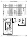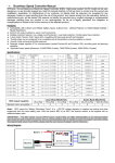
1
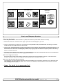
SE 40/125 S IP Ignition Protected thruster assembly SIDE-POWER Thruster Systems is rd th a p bo ee n K al o u an m ! SLEIPNER MOTOR AS P.O. Box 519 N-1612 Fredrikstad Norway Tel: +47 69 30 00 60 Fax: +47 69 30 00 70 w w w. s i d e - p o w e r. c o m s i d e p o w e r @ s l e i p n e r. n o © Sleipner Motor AS 2015 Made in Norway Installation and user manual Contents Technical specifications.............................................................. 2 Planning & important precautions.............................................. 3 Stern thruster installation considerations................................... 3 Bolt on installation ..................................................................... 4 Mould on installation .................................................................. 5 Gearhouse and motorbracket..................................................... 6 Oil tank & propellers.................................................................. 7 Electromotor IP assembly........................................................... 8 Electrical installation .................................................................. 9 Control panel and control-leads............................................... 10 Visual wiring diagram............................................................... 11 Technical wiring diagram ......................................................... 12 Electrical installation of stern thruster systems ........................12 Checklist................................................................................... 13 Important user precautions....................................................... 14 How to use Sidepower thrusters.............................................. 15 Maintenance............................................................................. 16 Troubleshooting........................................................................ 17 Warranty statement ................................................................. 18 Parts list.................................................................................... 19 Service centres ........................................................................ 20 DECLARATION OF CONFORMITY We, Sleipner Motor AS P.O. Box 519 N-1612 Fredrikstad, Norway declare that this product with accompanying standard remote control systems complies with the essential health and safety requirements according to the Directive 89/336/EEC of 23 May 1989 amended by 92/31/EEC and 93/68/EEC. Technical specifications Motor: Custom made reversible DC-motor. Gearhouse: Seawater resistant bronze. Ballbearing at propellershaft; combination of ballbearing and slide bearing at driveshaft. Motor bracket: Seawaterresistant aluminium. Ignition protection: Conforms to ISO 8846 Propeller: 5-blade Skew-back design "Q-prop" propeller, reinforced composite. Batteries: Minimum recommended battery capacity (cold crank capacity by DIN standard) SE40/125S-12V : 300 CCA DIN/570 CCA SAE Max. use: S2 = 3 min. or appr. 7-10% within a limited time frame. All electromotors are protected against overheating. Safety: Electronic time-lapse device protects against sudden change of drive direction. Electric thermal cut-off switch in electromotor protects against over heating (auto reset when electro motor cools down). Shearpin between electro-motor and driveshaft protects electromotor and gearsystem if propeller gets jammed. If original Side-Power panel is used, the panel shuts off automatically 6 minutes after last use. Integrated microprocessor monitors solenoids, reducing wear and risk of solenoid lock-in. Auto-stop of thruster in case of accidental solenoid lock-in or if run signal is continuous for more than 3 minutes. SE 40/125 S IP B Thrust at 10.5V/ 21V* (kg • lbs) A Thrust at 12V/ 24V* (kg • lbs) Typical boat size (ft • m) Tunnel I.D. (mm • in) Propulsion system Power at 10.5V/ 21V* (kw • Hp) For DC system (V) Weight (kg • lbs) Rec. CCA (DIN** 12/24V) Item Code 12V Item Code 24V Item Code 12V PRO* Item Code 24V PRO* 40 • 88 48 • 105 26’ - 34’ • 8 - 10.5 125 • 4.92’’ Single 2.2 • 3 12 10 • 22 300 Waterline III Responsible installer must consider and facilitating enough space and access regarding installation, service and maintenance of the thruster. IV II SE40/125S(-IP) V VI E SEP40/125S(-IP) D I Stern thruster I II IIIminIVmax V VI Tunnel (mm • in) Length SE40/125S IP 226 • 8.9 190 • 7.48 135 • 5.31 14 • 0.55160 • 6.3217 • 8.5 197 • 7.76 SE 40/125S ignition protected thruster assembly version 1.5 - 2015 2 Planning and important precautions Prior to installation, it is important that the installer reads this guide to ensure necessary acquaintance with this product. The electromotor assembly must be handled carefully. Do not put it down on the driveshaft. Beware to keep installation within advised measurements. We advice to paint the gear leg and propellers with antifouling. PS! Do not paint the zinc anodes, sealings or propellershafts. Do not finish the inside of the tunnel with a layer of gelcoat / topcoat or similiar. It is only room for a thin layer of primer and two layers of anti-fouling between the tunnel and the props. With the boat on land, only run the thruster for a fraction of a second, as without resistance it will accelerate very fast to a damaging rpm. Also, while the thruster is in air, make sure to avoid direction changes while the thruster is still running, as it might cause damage to the thruster. This manual is intended to support educated / experienced staff and is therefore not sufficient in all details for the correct installation. The thruster IP assembly has been tested to be fully ignition protected so that it can be installed in an area with the possibility of explosive gases in accordance to ISO 8846. Do not install the thruster in a position where you need to cut a stiffener/stringer/support for the hull integrity without checking with the boatbuilder that this can be safely done. When installed in boats approved or classified according to international or special national rules, the installer is responsible for following the demands in accordance with these regulations / classification rules. The instructions in this guide can not be guaranteed to comply with all different regulations / classification rules. NB ! Faulty installation of the tunnel, thruster or panel will render all warranty given by Sleipner Motor AS void. Stern thruster installation considerations To achieve maximum effect, reliability and durability from your Sidepower stern thruster, a correct installation is very important. Please follow the instructions carefully, and make sure that all checkpoints are carefully controlled. Additional considerations for positioning of the stern thruster Make sure that the stern-tunnel does not disturb the waterflow under the hull Ensure that when installed the thruster does not foul existing equipment inside the boat like steerage links etc. Make sure that the water flow from the thruster are not interfered too much by sterndrives, trimtabs etc. as this will reduce the thrust considerably. It is possible to mount the tunnel off the boat’s centre line if necessary. If the stern thickness is to much for the thruster in question you can easily remove hull material in the necessary area to fit the thruster. You only have to reduce the stern thickness down to the max. thickness measurement in the drawing. SE 40/125S ignition protected thruster assembly version 1.5 - 2015 3 Fig. 1 SEALANT Fig. 2 WASHERS LOCKNUT OR DOUBLE NUTS SEALANT Bolt on installation of the stern tunnel 1. Make sure that there are enough space both inside and outside the transom of the boat. 2. Once the place for the installation has been decided, hold the tunnel in place in the horizontal position and mark the bolt holes. Remove the tunnel and it is then possible to calculate and mark the centre. 3. It is important that the tunnel flange sits flush on the transom. If this is not so, then the area on the transom will have to be flattened to ensure a snug fit. PS ! Take care with grinders as it is very easy to remove to much in fibreglass At this time, cut out the centre hole and the transom to the same internal diameter as the tunnel flange and drill the bolt holes. Before bolting on the stern tunnel, the prepared area must be sealed with a gelcoat or similar to ensure there is no water ingress into the hull. If a bow thruster is also installed, we strongly advice to use separate battery banks for the two thrusters to avoid extreme voltage drop if both thrusters are to be used at the same time. Refer to the thruster manuals for advised battery capacity and cable sizes for each thruster. Also ensure that you do not have direct connections of both + and - if you have built together controls for both thrusters to avoid current leakage between separate battery banks. If you are installing the standard Side-Power dual joystick panel this is already secured. 4. Before fitting the tunnel to the transom, fit the lower gear leg to the tunnel as described on page 6. 5. When fitting the tunnel, ensure that there is ample sealant (Sikaflex or similar) in the sealing tracks of the tunnel flange and around the bolts to make a water tight fitting (Fig. 1/2). Bolts, washers and nuts are not included as they will wary depending on the transom thickness We recommend A4 stainless with A4 lock nuts and A4 washers of a large diameter on both outside and inside. Bolts diameter: ø 10mm or 3/8” stainless steel 6. Refer to the installation manual for the recommended thruster fitting. SE 40/125S ignition protected thruster assembly version 1.5 - 2015 4 Fig. 1 6 Fig. 2 5 4 3 2 1 D D 5 C C Bolt tightening forces: Bolts (2x) holding gearhouse to bracket: 17 Nm (12,4 lb/ft) 5 B B Designed by Date Material Type R. Hansen A Copyright All rights reserved SLEIPNERMOTORAS Drawing nr 13.09.2011 SM-101539 Weight Part nr N/A 6 5 4 3 Tolerance NS-ISO 2768-1 A Title 2 Size A3 Scale Edition 1 1 Sheet 1/1 Fitting gearhouse gearhouse and and motor motor bracket bracket Fitting 1. Try Try the the lower-unit lower-unit in the tunnel (remove the zinc anode) firstusing by using the gasket inside the tunnel. Trythe on propeller the propeller to make 1. anode) first by the gasket inside the tunnel. Try on to make suresure it is it is centred in the tunnel and turn freely with same clearance from each blade the tunnel (Fig. centred in the tunnel and turn freely with thethe same clearance from each blade toto the tunnel (Fig. 1).1). 2. Apply a thin thin layer layer of sealant sealant on both sides of the gasket gasket (5) and place it carefully on the gearhouse, making sure no sealant gets into 2. the oil or boltonholes on the gearhouse into theholes bolt holes the gearhouse (Fig 1). (Fig 1). 3. Push the the gearhouse gearhouse through through the the main main hole hole in in the thetunnel tunneland andpush pushthe thegearhouse gearhouseand andmotor-bracket motor-bracketgently gentlytogether. together. 3. 4. Screw the lower unit and the motor 4. motor bracket bracket together togetherwith withthe thetwo twoprovided providedbolts. bolts.Tighten Tightenwith with17 17Nm Nm/ /12,4 12,4lb/ft lb/ft(Fig. (Fig.2). 2). SE 40/125S - 2015 SP55S2iignition ignitionprotected protectedthruster thrusterassembly assembly version 1.1 - 1.5 2006 56 Fig. 1 1 2 4 3 Thread glue Fitting propellers 1. Push the propeller on to the shaft and turn until the internal spline in the propeller hub aligns with the external spline on the propeller shaft. 2. Push the propeller onto the shaft with the track for the drivepin in an horizontal position (same direction as you set the drivepin), all the way in. There should be almost no gap between the propeller hub and the gearhouse. 3. Place the washer (4) on the propeller shaft and then tighten the lock-nut (3) on the propeller shaft. 4. Place the anode (2) in its designated position and tighten the anode holding screw (1). Apply a thread glue (Loctite or similar) to ensure that the anode holding screw does not un-screw itself from the propellers rotation. Parts description: 1 : Screw for anode 2 : Anode 3 : Propeller lock nut 4 : Washer SE 40/125S ignition protected thruster assembly version 1.5 - 2015 6 D Fig. 2 Fig. 1 6 5 4 3 2 1 D C C B B Designed by Copyright All rights reserved A SLEIPNERMOTORAS 5 4 3 Date Material Type R. Hansen 6 Drawing nr 13.09.2011 SM-101539 Tolerance NS-ISO 2768-1 Designed by R. Hansen Title SLEIPNERMOTORAS Weight Part nr 5 N/A 2 Size 4A3 Scale Edition 1 1 Date Material Type A Copyright All rights reserved Sheet Drawing nr 13.09.2011 SM-101539 Weight Part nr 1 / 31 N/A 2 Fitting the electromotor IP assembly 1. Remove the 2 bolts in the motorbracket (Fig 1). 2. Use the enclosed template to measure that the driveshaft has come through the motorbracket with the correct height (Fig 2). 3. Place the motor assembly gently on the motorbracket. Make sure that the drive pin in motor drive shaft fits the into the corresponding grove in the gearleg shaft. Be careful, the motor is heavy! 4. Fasten the motor assembly to the bracket with the 2 bolts and cross tighten them first with 15Nm (11lb/ft) and then with 33Nm (24lb/ft). NB ! Paint the gear leg and propeller with antifouling for propellers to prevent growth of barnacles or similar which would reduce the performance dramatically. Do not paint the propeller shaft, the anodes or the end face of the gearhouse. NB ! Do not run the thruster for more than very short bursts without being in the water. SE 40/125S ignition protected thruster assembly version 1.5 - 2015 Tolera Title 7 Size A3 Scale Editio 1 1 6 5 4 3 2 1 D C *C RED: + *D B + Designed by Model 6 Voltage 5 SE40/125S SE30/125S 12 V Copyright All rights reserved Nominal Min. battery current CCA draw 4 280 195 A DIN: 300 200 SAE: 570 SAE:380 Material Type R. Hansen Battery & cable recommendations: AWG Date Drawing nr 30.08.2011 SM-101462 >7m total SL + E&IP-NER7-14m +&MOTORAtotal S 15-21m total + & - Min. 35 25 1 3 Tolerance NS-ISO 2768-1 A Title Part nr mm2 Battery 12V Weight Rec. Min. Rec.2 Min. 50 35 1/0 1 50 35 1/0 1 70 50 2/0 1/0 95 50 3/0 1/0 N/A Size A3 Scale Rec. 120 95 4/0 3/0 22-28m total + & Edition 28-35m total + & - 36-45m total + & - Rec. Min. Rec. Min. Rec. 2x95 120 2x 4/03/0 2x95 95 2x 3/03/0 2x120 2x70 2x 4/0 2/0 2x120 120 2x 4/04/0 260* 2x95 2x 3/0 Sheet 1/1 1 Min. 1 120 70 4/0 2/0 Minimum and recommended cable dimensions can be identical due to safety margins and cable heat considerations for short cable lenghts. * Minimum or recommended cable cross section in mm2 Electrical installation • Explanation of electrical table - All cable lengths are the total of + and - (to and from). - Battery size is stated as minimum cold crank capacity, not Ah. - Use slow fuse rated to hold stated Amp-Draw for min. 5 minutes. * Cable size and main battery size when an extra bow battery with minimum the CCA mentioned as A is installed. • It is important that you use a good cable size and batteries with a high cranking capacity to feed the thruster, because it is the actual voltage at the motor while running the thruster that decides the output RPM of the motor and thereby the actual thrust. Please see the list below for advised min. sizes of cables and batteries. You can of course use larger cables for even better results. • A main switch (*C) that can take the load without noticeable voltage drop must be installed in the main positive lead so the power for the thruster can be turned off independently of the rest of the system when not on board or in emergencies. This should be placed in an easily accessible place and the boats instructions should include information that this should be turned off like the other main switches of the boat. • We also advice to install a fuse (*D) in the positive lead for protection against short-circuiting of the main cables. This fuse should be of a adequate quality which normally means that it is physically large as these have less voltage drop than the simple / small ones. It should be of the slow type and sized to take the amperage draw for at least 5 minutes. • Remember to use ignition protected fuses and switches if fitted in areas that require this feature. • A circuit breaker can be used instead of the fuse and main power switch as long as the functionality is the same. • The cable ends must be fitted with terminals and these must be well isolated against contact with anything but the proper connection point. • If the main switch and fuse are installed in the same gas area they also have to be ignition protected. • The negative / minus cable connects to the (-) terminal. Bolt M10. Tighten with 20 Nm / 14.75 lb/ft. • The positive / plus cable connects to the "+" terminal. Bolt M10. Tighten with 20 Nm / 14.75 lb/ft. Place the included red protection cap firmly on the terminal bolt, as shown in illustration above. NB! Very important to check the following with mainswitch in off position: After all electrical connections have been completed, check with an ohm meter that there is no electrical connection between electro motor flange and positive terminal on the motor and between the electro motor flange and the negative (battery -) terminal on the motor. If you feel unsure on how to perform this check, contact skilled personnel for guidance. SE 40/125S ignition protected thruster assembly version 1.5 - 2015 8 Pin configuration in contacts 3 4 4 3 SIDEPOWER SIDEPOWER THRUSTER 1 2 THRUSTER 1 2 Connect round end of control adapter cable to the round socket on IP casing ON ON OFF SLEIPNER ON ON OFF SLEIPNER Control panel panel and and control-leads control-leads Control •• You as many many panels panels as asyou youwish wishby byusing usingoptional optionalY-connectors. Y-connectors.If Iftwo twooror more panels operated at the same time You can can install install as more panels areare operated at the same time in in opposite directions, the electronic controlbox will stop the thruster until it only receives a signal to go in one direction. opposite directions, the electronic controlbox will stop the thruster until it only receives a signal to go in one direction. •• When using original original Sidepower Side-Power equipment it is "plug & go". When using equipment it is allall "plug & go". •• IfIf the drive direction direction of ofthe thethruster thrusterisisthe theopposite oppositeofofwhat whatex-pected, expected,the theblue blueand andgrey greywire wire must changed each panel. the drive must bebe changed onon each panel. •• The installationof ofthe thepanel panelisisdescribed describedininthe themanual manualfollowing following the panel. The mechanical mechanical installation the panel. •• The is gas gas proof proofbased basedon onthe thecontrol controlpanel panellead leadending endingoutside outside the area that requires ignition protection. control The IP IP thruster thruster is ofof the area that requires ignition protection. TheThe prefitted adapter leadmust mustbe befitted fittedininthe theboat boat there risk damage to the insulation, causing explosive penetration. control lead soso there is is nono risk of of damage to the insulation, causing explosive gasgas penetration. •• The control should shouldbe beplaced placedininaaposition positionwere wereit itisiseasy easy use, and it very is very common to use thruster at the same The thruster thruster control toto use, and it is common to use thethe thruster at the same timetime as as your gear / throttle lever is normally a user friendly solution be to able to access withhand one for hand forcontrol. each control. your gear / throttle lever so itso is itnormally a user friendly solution to beto able access thesethese with one each Pin of44pole poleAMP AMPcontact: contact: Pin configuration configuration of Pin1:BLACK Pin1: BLACK = = Ground Ground Pin2: Pin2: BLUE BLUE = Engages thruster thruster SB SB solenoid solenoid = Engages Pin3: thruster Port Port solenoid solenoid Pin3: GREY GREY = = Engages Engages thruster Pin4: Pin4: RED RED = Positive voltage voltage for for control controlpanel panel = Positive SE 40/125S SP55S2iignition ignitionprotected protectedthruster thrusterassembly assembly version 1.5 - 2015 1.1 - 2006 9 10 red Battery main switch Battery 12V Thermal switch A1 brown M A2 black Fuse blue red red white grey 6 1232i Electronic control box 7 53 4 2 1 8 6 9 red grey blue black 4 3 2 1 "Visual" wiring diagram "Visual" wiring diagram SE 40/125S ignition protected thruster assembly version 1.5 - 2015 SP55S2i ignition protected thruster assembly 1.1 - 2006 10 11 Technical wiring diagram Round connector 4 pin AMP on motor housing connector On Motor blue (sig -) 4 red 3 Fused 9 red (+) inside 1A 4 8 blue (sig +) 2 Electronic interface box 6 1232i red white 7 2 black (-) 1 1 6 grey (sig -) 5 grey (sig +) 3 4 2 1 3 A2 black M brown A1 Fuse Thermal switch Battery main switch Electrical installation of stern thruster systems We advice to use different battery banks for each thruster to ensure maximum performance when both are used at the same time. When using the original Sidepower control cables just connect them to the corresponding joystick There are no plus/positive power connected from the bowthruster Visual connection diagram for dual joystick panel SIDEPOWER THRUSTERS To bowthruster BOW To sternthruster STERN ON ON OFF SLEIPNER Wiring diagram (simplified) for dual joystick panel yellow Joystick for bowthruster ON / OFF System grey blue black Positive lead from sternthruster have been removed in panel to avoid current leakage between different battery banks if the thrusters are powered by different battery banks. Control light STERN SE 40/125S SP55S2iignition ignitionprotected protectedthruster thrusterassembly assembly red grey blue black Joystick for sternthruster BOW version 1.5 - 2015 1.1 - 2006 12 11 Checklist Propeller is fastened correctly to the shaft. Propeller turns freely in tunnel. The anode holding screw is tightened well with thread glue. All electrical wiring, cable sizes and battery capacity is according to the thruster installation manual. All bolts are securely tightened and sealant are applied as instructed. Anti-fouling have been applied to the gearhouse and propeller but NOT on the anode or the gearhouse lid where the pro- peller is fastened. Correct drive direction as per controlpanel. All electrical connections are clean, dry and tight, and the correct cable, fuse and main switch sizes have been used. The bolts holding the gearhouse and motorbracket together are tightened correctly. Very important for IP protection: The main power cables have securely been connected as described. The control lead ends out of the explosive area and has been properly fitted and secured against damage. The thruster has been installed as per the instructions in this manual and all points in checklist above have been controlled. Signed: ..................................... Date: ....................................... Extra pre-delivery tests by installer / yard who does not use other quality control systems ! Thruster type: ................................................. Voltage: ...................... Serial number: ..................................................................................... Date of delivery: .................................................................................. Correct drive direction as per control panel: ....................................... Voltage at thruster when running: ...................................................... Battery cable size used: ..................................................................... Other comments by installer: SE 40/125S ignition protected thruster assembly version 1.5 - 2015 12 Important user precautions • Ensure that you know the location of the main battery switch that disconnects the thruster from all power sources (batteries) so that the thruster can be turned off in case of a malfunction. • Always turn the main power switch off before touching any part of the thruster, as an incidental start while touching moving parts can cause serious injuries. • Always turn the control device off when the thruster is not in use. • The maximum continues usage time of the electrical thruster is approximately 3 minutes. The electromotor has a built in thermal cut-off switch that will shut off the electromotor if it is overheating and re-engage it when it has cooled down some. This should be considered when planning your maneuvering. • This also means that the thruster will limit its total running time per time period so that you can not count on the thruster to hold you in a current and side wind for extensive time periods. Depending on the surrounding temperatures etc. the thruster will be able to run approximately 10 % of the time. • Never use a thruster close to somebody in the water, as the thruster will draw objects close by into the tunnel and contact with the rotating propellers will cause serious injuries. • With the boat on land, only run the thruster for a fraction of a second, as without resistance it will accelerate very fast to a damaging rpm. Also, while the thruster is in air, make sure that the propellers have come to a complete stop before performing a directions change of the thruster, as it might cause damage to the thruster. • If the thruster stops giving thrust while the electromotor is running, chances are that there is a problem in the drive-system. You must then immediately stop trying to run it, and turn it off, as running the electromotor for more than a few seconds without resistance from the propeller, can cause serious damage to the electromotor. • When leaving the boat always turn off the main power switch for the thruster. • We advice to always keep the main engine(s) running while using a thruster. This will keep the batteries in a good charge condition. This will also give better performance to the thruster, as a higher voltage at the thruster results in a higher torque (power) in the electromotor. • Please note that the performance of a thruster strongly depends on the voltage available at the electromotor. This voltage will decrease by time because aging batteries have a reduction of capacity. By installing new batteries the effect of the thruster should be back at the original level. • Make sure that only one control is used at the same time, if two panels are operated in opposite directions at the same time the thruster will not run at all. If they are operated in the same direction the thruster will run in this direction. • If the thruster is not performing or functioning as usual, the cause for this must be found and corrected as soon as possible so to avoid causing any other or further damage to the equipment. You must also turn off the main battery switch immediately in case the problem is of electric origin. • Never store anything (e.g. equipment, sails, ropes etc.) in the same compartment as the thruster. When the thruster runs for a longer period it will get hot and will cause damage. • It is the owner/captain/other responsible party full responsibility to as- sess the risk of any unexpected incidents on the vessel. If the thruster stops giving thrust for some reason while maneuvering you must have considered a plan on how to avoid damage to persons or other objects. Warning: Tampering with the Ignition Protected stern thruster assembly or any attempt to disassemble anything on this thruster assembly inside the boat can cause an explosion with very serious consequences. If there is a problem with your Ignition Protected stern thruster, please contact your dealer. Danger: NEVER Disassemble any part of the Ignition Protected stern thruster assembly SE 40/125S ignition protected thruster assembly version 1.5 - 2015 13 To turn panel ON Turn boat to port To turn panel OFF Turn boat to starboard Bow+Stern Thruster How to use Sidepower thrusters How to use use aabowthruster bow thruster 1. Turn main power switch for the bowthruster bow thrusteron. on.(Always (Alwaysturn turnoff offthe themain mainpower powerswitch switchwhen whennot notonboard.) on board.) 1. 2. thruster usage usage in open water to avoid damages damages to your boat. 2. Please take some time to exercise thruster 3. panelon onby bypushing pushingboth both"ON" "ON"buttons buttonson onthe theoriginal originalSidepower Side-Power panel simultaneously. If another type of control 3. Turn the control controlpanel panel simultaneously. If another type of control is is installed, engage the the On/Off On/Off switch switch for for the the bowthruster. bow thruster. installed, engage 4. direction by by pushing pushing the the red red button buttonfor forport portmovement movementororthe thegreen greenbutton buttonfor forstarboard starboardmovement. movement.If Ifyou you 4. Turn the bow in the desired direction have a joystick control, control, move move itit in in the the direction direction you you wish wishthe thebow bowto tomove. move.Other Othercontrols controlslike likefootswitches foot switches toggle-switches or or toggle-switches on on thethe throttle can be be used. used.These Theseare arenormally normallylogically logicallyinstalled, installed, engaging control, goes In case of any throttle can soso byby engaging thethe portport control, the the bowbow goes portport etc.etc. In case of any doubts, try in open waters waters first. first. 5. on the the sideways sidewaysspeed speedofofthe thebow, bow,you youmust mustdisen-gage disengagethe thecontrol controldevice deviceshortly shortlybefore beforethe thebow bowisisininthe thedesired desired direc5. Depending Depending on tion, as the will continue to move after after stopping the bow thruster. direction, asboat the boat will continue to move stopping the bowthruster. How to use use aa single singlestern sternthruster thruster Some boats might however have installed a single stern thruster because because of space limitation limitation in in the bow. In this case the stern thruster is used in the same way as a single single bow bow thruster thruster (see above) for moving the boat's stern. How to use use aabow bowand andstern sternthruster thrustercombined combined The combination combination of of aa bow bow and and stern stern thruster thruster offers offerstotal totalmanouverability manoeuvrabilitytotothe theboat boatand andthe theopportunity opportunitytotomove movethe thebow bowand andthe the stern separately separately from from each each other. other. This This enables enables you you to to move move the the boat boat sideways sideways in in both both directions directionsand andto toturn turnthe theboat boataround aroundit's it'sown own axis staying the same axis staying at theatsame place.place. • Again, if in doubt, try in open water first! • Again, if in doubt, try in open water first! SE 40/125S SP55S2iignition ignitionprotected protectedthruster thrusterassembly assembly version 1.5 - 2015 1.1 - 2006 14 15 1 2 3 4 Electromotor assembly Composite 5-blade propeller for ultimate performance. Pre-filled lifetime lubricated gearhouse. Changeable anode protects gearhouse from corrosion in seawater. 1 3 2 4 1 2 4 3 Thread glue 1 2 3 4 5 Fastening screw for anode Anode Propeller lock nut Washer Drivepin for propeller Maintenance » Keep the propeller and gearhouse clean from growth by painting with antifouling before every season. PS ! The anode, sealing and propeller shafts must absolutely not be painted. Be careful that you don't fill paint in the "tracks" in the gearhouse that the propeller hub moves in. » Change the anode before every season, or when about half the anode is gone. Always use a sealant on the screw holding the anode to ensure that it does not fall off. Please observe that in some water conditions it can be necessary to install an extra anode to ensure that it lasts for the whole period between regular service lifts of the boat. Consult your dealer for information on how to do this. » As a part of the seasonal service of your boat, and before every season, always check that: • The propeller is securely fastened • The bolts holding the electric motor to the motor bracket are fastened correctly. • The area where the thruster is installed is clean and dry. If there are signs of water you must try to find the source and eliminate it. • All electrical connections are clean and fastened firmly. • Make sure that your batteries are in a good condition so that the thruster gets a good voltage. Old or bad batteries will give a reduced performance from the thruster. Warning: Tampering with the Ignition Protected stern thruster assembly or any attempt to disassemble anything on this thruster assembly inside the boat can cause an explosion with very serious consequences. If there is a problem with your Ignition Protected stern thruster, please contact your dealer. Danger: NEVER Disassemble any part of the Ignition Protected stern thruster assembly SE 40/125S ignition protected thruster assembly version 1.5 - 2015 15 Troubleshooting Before seeking assistance at the help desk of your Sidepower dealer / distributor please perform these tests and make notes of all measurements to ensure that they have as much information as possible to work on. NB! All check points and solutions must be carried out after consulting the relevant information elsewhere in this manual to understand how the system is intended to work. If you are unable to understand what to check, you must consult a professional. » » » » Check If the drive pin on the motor shaft is broken Remove motor and replace the drive pin Are the propellers in the tunnel fastened correctly on the prop-shaft (key present) Re-fasten or replace the propeller and/or key. With the motor removed, turn the driveshaft from inside the boat to feel if the gears are engaging and turning the prop-shaft. In case of a failure inside the gearhouse, we advice to get a replacement gear-house instead of attempting to repair the internal gear and bearing system. The thruster does not start at all or works only in one direction. Check that the voltage of the electromotor are correct for your installation by their labels. If wrong, contact your dealer or distributor to obtain parts with the correct voltage. Check the voltage at the thruster between main minus input and main plus input point: The no load voltage should be: 12V system =12,7V. If below 12,3V, your batteries are not in a good charge state or worn out and must be recharged or replaced before trying to run the thruster. Check the voltage at the thruster while you are trying to run it. Keep main engine(s) running to have continous charge to the batteries. If less than 8,5V at the thruster the voltage is to low for the thruster to operate correctly. Find and correct the reason for this low voltage which will probably be one or more of these points: main battery cable sizes and connections, battery size and condition, fuse and main power switch performance. If the main solenoids on the thruster are not even trying to engage (clicking) they are probably not getting a "run" signal from the control system. Try to run the thruster without the panel by directly connecting the red and the blue or the red and the grey wires in the controlcable contact coming from the thruster. If the thruster runs in both directions, try the same in the connector that goes into the back of the control panel. If it also works in this position, check the contact and wires on the back of the panel and try to engage this again by pushing both ON buttons simultaneously. If the panel does not turn on (see control light), measure the voltage between the Red and the Black in the contact going into the thruster. If the voltage is good, chances are that the panel is not working. If it works by the thruster, and not by the panel there is a bad contact or a broken lead in the controlcables between these two test points. Measure that you have the correct voltage between the Red (+) and all the other colours in the contact. If you do not get a reading. If the thruster does not run at all, or only in one direction in the above tests, check the internal wiring on the thruster motor, solenoids and electronic motor inter-face box to be in accordance with the wiring diagram and ensure that all connections are clean and tight. Between main minus (A1 on motor) and the blue and the grey wire connected to the sides of the main solenoids you should have the same voltage as between the main battery cables on the thruster. If not, check that the internal wiring on the solenoid is ok and measure that there is contact through the magnetising spools of each side of the solenoid (measure between the red and blue on one side, and red and grey on the other side with an Ohm meter.). If there are no contact between these, the solenoid is broken and needs replacing. The thruster has an unexpected low performance. Check voltage at thruster when running If less than 10,5 V, the thruster will not perform at specified effect. Check that all the brush-springs sits correctly on the brushes in the electromotor. If one or more brushes are loose/has no tension from the brush-spring, the performance will be low. Check that the propeller, gearhouse and tunnel is free from growth / barnacles etc. If there are growth in the tunnel, this will disturb / block the waterflow and especially barnacles on the propeller will greatly reduce performance. The thruster runs for approximately 0,5 seconds every 4 seconds. Solenoid flapping, most probable cause: low voltage. » Solution The electromotor runs, but there is no thrust. Re-charge battery(ies), if this is not sufficient, replace battery(ies). Check for bad cable connections, if necessary tighten/re-adjust connections. Check cable size in accordance to manual. The thruster runs for approximately 0,5 seconds every 10 seconds. Solenoid lock-in, auto stop of thruster, auto retry every 10 seconds. Shut off thruster main switch, tap slightly on the motor to see if it will release. Turn on thruster main switch. If solenoid is still in lock-in mode, contact your dealer. SE 40/125S ignition protected thruster assembly version 1.5 - 2015 16 Warranty statement 1.The equipment manufactured by Sleipner Motor AS (The “Warrantor”) is warranted to be free from defects in workmanship and materials under normal use and service. 2.This Warranty is in effect for of two years (Leisure Use) or one year (Commercial use) from the date of purchase by the user. Proof of purchase must be included, to establish that it is inside the warranty period. 3.This Warranty is transferable and covers the product for the specified time period. 4.In case any part of the equipment proves to be defective, other than those parts excluded in paragraph 5 below, the owner should do the following: (a) Prepare a detailed written statement of the nature and circumstances of the defect, to the best of the Owner’s knowledge, including the date of purchase, the place of purchase, the name and address of the installer, and the Purchaser’s name, address and telephone number; (b) The Owner should return the defective part or unit along with the statement referenced in the preceding paragraph to the warrantor, Sleipner Motor AS or an authorized Service Centre, postage/shipping prepaid and at the expense of the Purchaser; (c) If upon the Warrantor’s or Authorized Service Centre’s examination, the defect is determined to result from defective material or workmanship, the equipment will be repaired or replaced at the Warrantor’s option without charge, and returned to the Purchaser at the Warrantor’s expense; (d) no refund of the purchase price will be granted to the Purchaser, unless the Warrantor is unable to remedy the defect after having a reasonable number of opportunities to do so. Prior to refund of the purchase price, Purchaser must submit a statement in writing from a professional boating equipment supplier that the installation instructions of the Installation and Operation Manual have been complied with and that the defect remains; (e) warranty service shall be performed only by the Warrantor, or an authorized Service Centre, and any attempt to remedy the defect by anyone else shall render this warranty void. 5.There shall be no warranty for defects or damages caused by faulty installation or hook-up, abuse or misuse of the equipment including exposure to excessive heat, salt or fresh water spray, or water immersion except for equipment specifically designed as waterproof. 6.No other express warranty is hereby given and there are no warranties which extend beyond those described in section 4 above. This Warranty is expressly in lieu of any other expressed or implied warranties, including any implied warranty of merchantability, fitness for the ordinary purposes for which such goods are used, or fitness for a particular purpose, and any other obligations on the part of the Warrantor or its employees and representatives. 7.There shall be no responsibility or liability whatsoever on the part of the Warrantor or its employees and representatives for injury to any person or persons, or damage to property, loss of income or profit, or any other consequential or resulting damage or cost which may be claimed to have been incurred through the use or sale of the equipment, including any possible failure or malfunction of the equipment, or part thereof. 8.The Warrantor assumes no liability for incidental or consequential damages of any kind including damages arising from collision with other vessels or objects. 9.This warranty gives you specific legal rights, and you may also have other rights which vary from country to country. SE 40/125S ignition protected thruster assembly version 1.5 - 2015 17 27 28 26 25 24 23 30 S2iprotected / SP 40 S2ithruster / SP 55 assembly S2i 3.7 - 2006 SE 40/125SSP ignition version 1.5 - 2015 21 4 3 1 11 22 10 13 21 17 19 16 5 7 10 18 28. 27. 26. 25. 24. 23. 22. 21. 20. 19. 18. 17. 16. 15. 14. 13. 12. 11. 10. 9. 8. 7. 6. 5. 4. 3. 2. 1. w hen ordering brushes and brush springs. * Please provide thruster serial number Other comments: 6 8807 3 2026 3 0131 12 41472123 6 1226B 6 1232i 3 0135 3 2050 3 1143 N/A 3 0170 12* 3 0180 12* N/A N/A 3 0501 N/A 3 0601 3 1080 N/A N/A 3 1310 10 N/A 3 1180 3 1250 3 1365 N/A 1261 3 31260A Ref: 3 3 0102 0101 12 12 02/05 < 09/07 < SE S SP40/125 40 S2i Part # 12V Com plete electric motor assem bly Nut for solenoid cover Solenoid cover Complete solenoid kit Solenoid Internal w iring loom Electronic control box Solenoid bracket kit Shear pin f or electric motor shaft Retaining ring Electric motor Brush springs for electric motor (kit) Brushes for electric motor (kit) Oil container w ith holder Oil hose with hose clam ps Com plete motor bracket O-ring seals in motor bracket Com plete gearleg Gearleg bolt Drive shaft seal Propeller shaft seal Gasket Oil drain screw w ith gasket Anode Locknut Propeller w asher Propeller drive pin Propeller Model period Original model SP 40 S2i PARTS LIST - SE 40/125 S 51 18 SE 40/125S ignition protected thruster assembly version 1.5 - 2015 19 Worldwide sales and service www.side-power.com SLEIPNER MOTOR AS P.O. Box 519 N-1612 Fredrikstad Norway Tel: +47 69 30 00 60 Fax:+47 69 30 00 70 www.side-power.com [email protected]